-
PDF
GT30L24A3W_V1.0I_C.PDF
上海高通半导体有限公司 GT30L24A3W 标准点阵中外文字库芯片 GT30L24A3W Multi Language Dot Matrix Font Chip DATASHEET V 1.0I_C 2017-5 1 www.genitop.com 上海高通半导体有限公司 GT30L24A3W 标准点阵中外文字库芯片 Revision History Version Modify Content Date Remark Number
in „Suche Info's zum Fontspeicher GT30L24A3W“ · Mikrocontroller und Digitale Elektronik ·
-
Datei
lader_v11.asm
3 (V24) ; 0 1 0 1 1 0 1 1 = 5Bh Modus + 4 (V24 mit DTR) ; 1 0 1 0 0 0 1 1 = A3h Modus 5 (Drucker) ; 1 1 0 0 0 0 1 1 = C3h Kasettenbetrieb ; ; fuer die Nutzung der Realais 0 u. 1 sind die Bits 0 u. 1 entsprechend
in „Suche MOPPEL Projekt in Heft oder .PDF“ · Mikrocontroller und Digitale Elektronik ·
-
PDF
Binder-M16-IP67-23.pdf
79 08 1 12 4–6 mm – 09 0129 25 12 12 6–8 mm – 09 0129 70 12 M 14 4–6 mm – 09 0451 25 14 14 6–8 mm – 09 0451 70 14 16 4–6 mm – 09 0505 25 16 16 6–8 m m – 09 0505 70 16 V 19 4–6 mm – 09 0461 25 19 19 6–8 mm – 09 0461 70 19 24 4–6 mm – 09 0495 25 24 24 6–8 mm – 09
in „14 pol. Steckverbinder mit hochwertigen Kontakten gesucht“ · Mechanik, Gehäuse, Werkzeug ·
-
PDF
1-kmy24.pdf
Measurements taken with 5 cm high, cylindrical metallic objects, moving in circles at a distance of 1 m for example, give signal amplitudes of typiD1lly0 mV. Data Sheet 2 1999-04-01 KMY 24 Output Signal The phase difference between V and V is positive, if the target is receding from the D2 D1 detector. (ϕ1 —ϕ 2 ≥ 0 EHA07261 VD1 Receding VD2 Ch1 10mV Ch2 10mV M 100ms The phase difference between VD2 and V D1 is negative, if the target is approaching the detector. (ϕ1— ϕ 2 ≥ 0 EHA07262 Approaching V V D1 D2 Ch1 10mV Ch2 10mV M 100ms Data Sheet 3
in „Phasenverschiebung Auswerten“ · Mikrocontroller und Digitale Elektronik ·
-
PDF
1-kmy24.pdf
Measurements taken with 5 cm high, cylindrical metallic objects, moving in circles at a distance of 1 m for example, give signal amplitudes of typiD1lly0 mV. Data Sheet 2 1999-04-01 KMY 24 Output Signal The phase difference between V and V is positive, if the target is receding from the D2 D1 detector. (ϕ1 —ϕ 2 ≥ 0 EHA07261 VD1 Receding VD2 Ch1 10mV Ch2 10mV M 100ms The phase difference between VD2 and V D1 is negative, if the target is approaching the detector. (ϕ1— ϕ 2 ≥ 0 EHA07262 Approaching V V D1 D2 Ch1 10mV Ch2 10mV M 100ms Data Sheet 3
in „Richtungsabhängiger Bewegungsmelder“ · Mikrocontroller und Digitale Elektronik ·
-
PDF
ten15-2411wi.pdf
1’250 mA 85 % (24 VDC nominal) TEN 15-2422WI ±12 VDC ±625 mA 85 % TEN 15-2423WI ±15 VDC ±500 mA 86 % TEN 15-4810WI 3,3 VDC 3’000 mA 78 % TEN 15-4811WI 5,1 VDC 2‘950 mA 82 % 18 – 75 VDC TEN 15-4812WI (48 VDC
in „Raspi Shield - so in Ordnung?“ · Mikrocontroller und Digitale Elektronik ·
-
PDF
DAC904_14-Bit_165MSPS_Digital-to-Analog_Converters.pdf
Capacitance 5 pF POWER SUPPLY Supply Voltages +VA +2.7 +5 +5.5 V +VD +2.7 +5 +5.5 V Supply Current6) I 24 30 mA VA VA, Power-Down Mode 1.1 2 mA VD 8 15 mA Power Dissipation +5V, I = 20mA 170 230 mW OUT +3V, IOUT= 2mA 50 mW Power Dissipation, Power-Down Mode 45 mW Thermal Resistance, θ JA SO-28 75 °C/W TSSOP
-
PDF
DFUE-1-6.pdf
empfangen, abbruch nach 10s mit Control-Z (1ah) mv24tx equ wboot+3ch ; (C) Byte senden ;v24txz equ wboot+3fh ; (C) Byte senden, abbruch wenn Geraet nicht bereit ; V24 auf CF-Karte ; cv24ist equ wboot+42h ; Status (A)=00h kein Zeichen, FFh Zeichen cv24rx
in „Suche MOPPEL Projekt in Heft oder .PDF“ · Mikrocontroller und Digitale Elektronik ·
-
PDF
Komarabathuni_Ravi_V.pdf
maximum unambiguous range R unbeyond which signals appear as second time around echoes is given by [5]: c R un [m] (2.2) 2f p Where fp is the Pulse Repetition Frequency (PRF) (Hz). Figure 2 shows the plot for maximum unambiguous range R unas a function of PRF f p. 24 4 10 ] l m a 3 i10 u [ e n a s o u102
in „Auslesen eines Bosch LRR Radar“ · Mikrocontroller und Digitale Elektronik ·
-
PDF
SUN-M101T2-03_VerA.pdf
1 N号N型 L称T公 T期 6 X A D组 T名R注 D日 1 P料M模 U未 5 + - 0 色 色 2 红 黑 E本 A例 9 R A S 6 - 版 比 2 00 SAMPLE 5 3± 24.35±0.5 5 65 KCAB TNORF m 0 1 I =8 U * R mA C 20 4 , 4 E AE L 4 R = N K * C O 3 E C A O K A E 6 E 0 D N - A E L X M I 7 m 3 I P . T B C 8 6 3 T . U 2 T R R H / O 2 9 . " X D _ ) 3 4 2 . 2 G T P 2 2 1 1 E I G T N W / ( C I V - 9 E V I 8 . A K I 8 : 55 V O O X C C H 16 C L P _ G 2 (( A ' E C 0 0 L 2 2 O I U ~ ~ C 0 6 O C C A N I : °° B : T O M C 0 0 F E B T T N I P - O N R E E R N E P O R P R T I T M H E (71.5) T D R
in „LVDS - Keine Ahnung bei Verbindung Board und Display“ · Mikrocontroller und Digitale Elektronik ·
-
PDF
Servoverstaeker_4-Q-EC.pdf
+ 22 Monitor soll Monitor Tacho Monitor soll Index Kanal I Index Kanal /I Abschirmung Abschirmung 24 Schutzerde 26 Kanal /B Kanal B Kanal /A 18VAC Power 1 28 Kanal A n.c. Abschirmung 18VAC Power 2 30 Resolver Primär GND Primär cos + n.c. cos - sin + sin - 32 Bemerkung: (SPS) kennzeichnet Überwachungssignale
in „Netzeil für Servoverstärker und Motor“ · Mikrocontroller und Digitale Elektronik ·
-
PDF
MP650_datasheet.pdf
TM i Play Media Player Controller M P 6 5 0 U C G Datasheet Revision 0.95 2010-03-24 TM iPlay MP650UCG Media Player Controller Datasheet Revision History Date Revision Description Nov. 10. 2009 0.9 Initial Draft Mar. 23, 2010 0.95 1. Update
in „Handydummy (Attrappe)mit richtigem Display 10Zoll - u.a.Motorola Xoom“ · Mikrocontroller und Digitale Elektronik ·
-
PDF
TPS_40210.pdf
current in For conduction losses to be (arbitrarily) 1% of each component. the total losses, a Pout×0.01 24×0.01 R DS(ON) = 2 = �100 mΩ . RMS 2.25 VIN R1 C7 TPS40210 L1 1 RC VDD 10 VOUT C6 2 SS BP 9 D1 Q1 R6 C3 3 DIS/EN GDRV 8 C2 R2 R4 C1 R3 4 COMP ISNS 7 C4 5 6 C8 R7 R8 FB GND C5 R5 Fig. 30. Schematic for
in „Problem mit dem Hochsetzsteller (TPS 40210)“ · Analoge Elektronik und Schaltungstechnik ·
-
PDF
SF_ISF.pdf
mA 70% ISF2405A †^ (1) (1) Setpoint Accuracy • 100-110% of nominal at 10% load 24 VDC 9.0 V 110 mA 72% ISF2409A †^ 12.0 V 84 mA 75% ISF2412A †^ (1) Ripple & Noise • Single output: 100 mV pk-pk, (1) 15.0 V 67 mA 76% ISF2415A †^ Dual output: 75 mV pk-pk, 24.0 V 42 mA 77% ISF2424A†^ 20 MHz bandwidth Opuft Temperature Coefficient• 0.03%/°C 1. For dual output models, delete suffix ‘A’ at the end of the part number
in „Verständnissproblem bei Schaltplan ISF0305A“ · Analoge Elektronik und Schaltungstechnik ·
-
PDF
3_3-5V.pdf
mA 70% ISF2405A †^ (1) (1) Setpoint Accuracy • 100-110% of nominal at 10% load 24 VDC 9.0 V 110 mA 72% ISF2409A †^ 12.0 V 84 mA 75% ISF2412A †^ (1) Ripple & Noise • Single output: 100 mV pk-pk, (1) 15.0 V 67 mA 76% ISF2415A †^ Dual output: 75 mV pk-pk, 24.0 V 42 mA 77% ISF2424A†^ 20 MHz bandwidth Opuft Temperature Coefficient• 0.03%/°C 1. For dual output models, delete suffix ‘A’ at the end of the part number
in „Das große ADC Quiz“ · Mikrocontroller und Digitale Elektronik ·
-
PDF
NDP6020P.pdf
INVERTED PULSE WIDTH Figure 11. Switching Test Circuit . Figure 12. Switching Waveforms . NDP6020P Rev.C1 Typical Electrical Characteristics (continued) 30 100 S V DS = - 5V 1 N 60 M I µs M24 N)LI I T = -55°C ) DS(O 1m ( J ( 30 R s E N C18 E A 25°C R 1 0ms T U U C 10 100 D12 125°C I m s N A DC C D 5 V GS
in „P-Channel High-Side Switch 3,3V“ · Mikrocontroller und Digitale Elektronik ·
-
PDF
PS-08-50-001.pdf
initial]) Thermal Aging 96 hours at 105 ± 2°C & Visual: No Damage MOLEX KK 396 WEB PAGE TABLE OF CONTENTS REVISION: ECM INFORMATION: TITLE: SHEET No. EC No: 686568 PRODUCT SPECIFICATION U DATE: 2021/11/24 .156 CENTER KK CONNECTORS 12 of16 DOCUMENT
in „wo bekommt man diesen Steckverbinder - Joint Tech?“ · Mechanik, Gehäuse, Werkzeug ·
-
 Bild
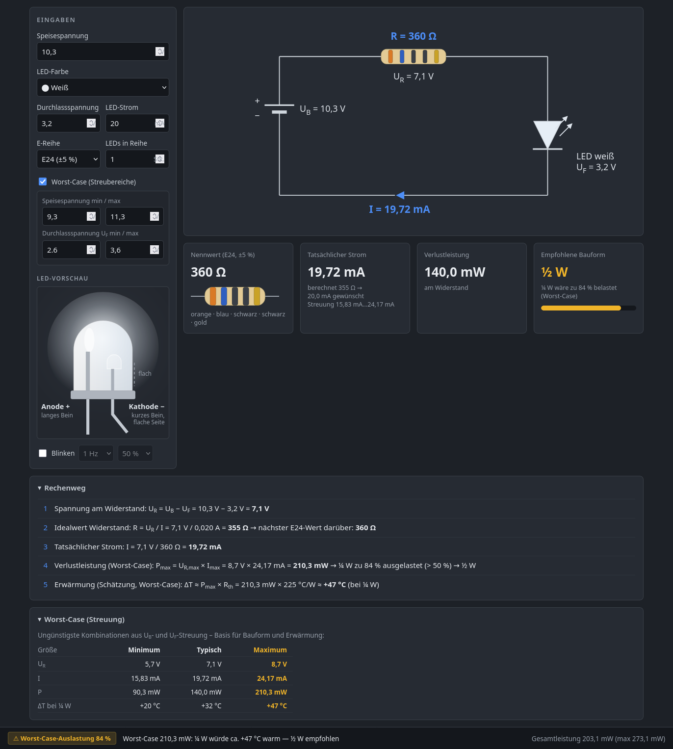
Rechnerisches Tool zur LED-Widerstandsberechnung
(Schätzung, Worst-Case): ΔT = Pmax * R = 210,3 mW * 360 Ω = +47 °C (bei 1/4 W) Worst-Case (Streuung) Ungünstigste Kombinationen Us und I-Streuung - Basis für Aufbau und Erwärmung Größe Minimum Typisch Maximum Us 5,7 7,1 8,7 V I 15,83 mA 19,72 mA 24,17 mA P 90,3 mW 140,0 mW 210,3 mW ΔT bei 1/4 W +20 °C +32 °C +47 °C Worst-Case-Auslastung 84 % Worst-Case 210,3 mW wäre ca. 47 °C warm - 1/4 W empfohlen Gesamtlast 201
in „LedPreResistor 2.1: Vorwiderstandsrechner für LEDs (Lazarus, MIT, Win64)“ · Projekte & Code · · Screenshots
-
PDF
PCA9532-1127723.pdf
protection exceeds 2000 V HBM per JESD22-A114, 150 V MM per JESD22-A115 and 1000 V CDM per JESD22-C101 Latch-up testing is done to JEDEC Standard JESD78 which exceeds 100 mA Packages offered: SO24, TSSOP24, HVQFN24 3. Ordering information Table 1. Ordering information Tamb = 40 C to +85 C. Type
in „[V] 3St. 16 Bit I2C/SM Bus LED Treiber PCA9532BS (HVQFN24)“ · Markt ·
-
PDF
mps-mp1010bef_2016abaf5e.pdf
Inc. The MP1010B is covered by US Patents 6,633,138, 6,316,881, 6,114,814. TYPICAL APPLICATION t Rs C 1 m f R C c C b Rdamp N1 f C C CbtR R Cp 0 9 8 7 6 5 4 3 2 N/A 2 1 1 1 1 1 1 1 1 1 D B L T P F N R D R HV N F O F M R I U N S 2 A C O P B Rbosc MP1010B T1 1 S T N T s CN1 B I B T E D I O P B C J1 1 2 3 4 5 6 7 8 9 1 ABRT 5 b Rabr Cabr r C d DBRT 4 Rbdr C EN 3 Ren1 d Cisb s / s r e 2 L e C N l R esd b d C e b b f f i R C C R C R C R R GND 2 a a C C F1 / 1A VBATT 1 FUSE MP1010B Rev. 2.2 www.MonolithicPower.com 1 9/24/2007 MPS Proprietary
in „Laptop LCD inverter board frage“ · Analoge Elektronik und Schaltungstechnik ·
-
PDF
ADV7175A.pdf
Color Bars No Pedestal V Levels W T E O N E K A I L A E G D U A W N N H E Y R A E L L T L N E E E C W Y C G M R B B H L A R A D U A 467mV W Y C G M R B B 467mV 309mV 391mV 158mV BETACAM LEVEL BETACAM LEVEL 76mV 0mV 0mV 0mV –76mV 0mV –158mV –309mV –391mV –467mV –467mV Figure 62. NTSC 100% Color Bars
-
PDF
NPX-35TFR-product-data-sheet.pdf
2.9 79 3.11 56 2.20 105 4.13 1.24 2.73 1 A/C NP3-12 NP3-12FR 3.0 132 5.20 33 1.30 105 4.13 1.18 2.60 1 A/C NP3.4-12 NP3.4-12FR 3.4 134 5.28 67 2.64 67 2.64 1.39 3.06 3 A/C NP4-12 NP4-12FR 4.0 90 3.54 70 2.76 107 4.21 1.70 3.74 1 A/C
in „[S] Polschutzkappen für 5.5mm Anschlüsse von Akkus“ · Markt ·
-
PDF
Grundig-DVDP-7000-Service-Manual.pdf
p la y B oard – V id e o P r o c e s so r U N D I G to P. 2-13 VCC S e J301 r 1 C 24 23 v 2 CVBS/Y_O c 3 MODE1 R351 R350 R349 R348 R347 R345 R343 R366 e 4 MODE2 C347 12K 560 27K 27K 5.6K R346 12K 27K 6.8K PIC:3V 5 Z3 I M M G B B 5.6K
in „800x480-Farbdisplay mit uC verwenden“ · Mikrocontroller und Digitale Elektronik ·
-
PDF
71006566_de.pdf
E-6566/021 Geraeteanordnung: Maschine 1 E-6566/022 Geraeteanordnung: Maschine 2 E-6566/GL1C Geraeteliste E-6566/ZU1C Zusatzblaetter Blatt 1 von 1 M A H O 28/02/89 E-6566/GL1 C Aktiengesellschaft G E R A E T E L I S T E D-8962 Pfronten MH 500 W/ 525 WIR/IHI Aenderungsdatum: 20.06.1989 Nr.---
in „CRT Monitor gegen VGA Monitor tauschen“ · Analoge Elektronik und Schaltungstechnik ·
-
PDF
2400fa.pdf
Unadjusted Error (3V Supply) 10 10 10 VCC = 3V V CC= 3V VCC = 3V VREF = 3V V REF= 3V VREF = 3V TA= 90°C 5 5 5 T = –55°C, –45°C, 25°C, 90°C m m A m TA= 25°C p p p ( 0 ( 0 ( 0 O O O R R R T = –45°C E TA= –55°C, –45°C, 25°C, 90°C E E A –5 –5 –5 TA= –55°C –10 –10 –10 0 0.5 1.0 1.5 2.0 2.5 3.0 0 0.5 1.0 1.5
in „hochauflösende Temperaturmessung“ · Mikrocontroller und Digitale Elektronik ·
-
PDF
VCR-SAT1.pdf
AR_DEC IN 2 c l P 22 AGCL 23 AL_DEC O U T 3 D 7;11;15 e C 4 10 e s Demodulator 24 PLL 24 AR_DEC O UT 1 16 k a Mixer i M ONO J17 / 75s r d D J17L 30 a U o C N 37 p / B B n n c B 75µsL Demo- m N F G i k t I dulator
in „Lieber OSD LC74776, zeig mir ein Bild“ · Mikrocontroller und Digitale Elektronik ·
-
PDF
WX_Station.pdf
1 3 Q? Q? 3 1 4 4 r IRF7842 IRF7842 r t 1 1 t +3V3 2 4 4 2 R? 1 1 R? 3V3 4 5 J? _ 220 Q? Q? 220 _ M 4 IRF7842 IRF7842 4 M GND AC_IN P 3 3 P 1 8 8 24V_AC Q? HEATER_2_0 HEATER_2_1 Q? +3V3 2 1 BSS138 BSS138 1 GND 3 12V_AC C C 2 2 4 COM_AC U? R? R? 4k7 GND GND 750 IS126 1 4 24V_AC ZEROCROSS +5V U? 12V_AC
in „Weller WX/WSM/WHS Serie Kabel Reverse Engineering“ · Mikrocontroller und Digitale Elektronik ·
-
PDF
Powersoft_DigiMod_1000_schematic.pdf
4 P 1 1 1 R91 CN9-27 3 NC Q7 2 2 4 3 D D C C BD237 1 D10 VCC1 ES3D 5 E / E 0 u C131 CN13 V C 2 1.0uF/16V 16P 2.54mm180° 8 3 2 1 U16-1 V 3 U11 R53 CN15 VCC3 1 2 VCC3 5 4 F C134 C84 2*5P 43045-1012 + U12 U16 JP5 2 C 0 L4941BDT 100K▯ ±1% 3 4 M24C16WMN6TP
in „Powersoft DigiMod 1500 Endstufe - DC Offset am Ausgang“ · Analoge Elektronik und Schaltungstechnik ·
-
PDF
W25Q64FV.PDF
Serial Number and four 256-bytes Security Registers. 2. FEATURES Family of SpiFlash Memories – 4mA active current, <1µA Power-down (typ.) – W25Q64FV: 64M-bit / 8M-byte (8,388,608) – -40°C to +85°C operating range – Standard SPI: CLK, /CS, DI, DO, /WP, /Hold Flexible Architecture with 4KB sectors
-
Datei
logFile.txt
ATI Radeon X600 (RV380) 3E50 (PCIE), ATI FireGL V3200 (RV380) 3E54 (PCIE), ATI Radeon Mobility X600 (M24) 3150 (PCIE), ATI FireGL M24 GL 3154 (PCIE), ATI Radeon X300 (RV370) 5B60 (PCIE), ATI Radeon X600 (RV370) 5B62 (PCIE), ATI FireGL V3100 (RV370) 5B64 (PCIE), ATI FireGL D1100 (RV370) 5B65 (PCIE), ATI
-
Datei
TopAS21.vhd
LSB in FP Format -20,5 --X"b2", -- --X"71", --4871b2c0 = 247499 Imp/U Roboterarm,gemesssen --X"48", --23,MSB A1res ,Achse A2,1:99,Motor2500 Imp/U ---23 -------------- --X"80", --24,C_A2res LSB in FP Format --24,6 --X"3e", -- --X"ed", --47ed3e80=121469 Imp
-
PDF
mOHm-Meter.pdf
L E 6 _ 0 1 2 3 4 5 6 7 8 9 0 2 3 4 5 7 - 0 1 2 3 4 5 6 7 8 9 0 2 3 4 5 7 5 I5 O5 14 L E 7 1 I A B C D X X X X X X X X X XX X X X X X 0 1 I A B C D X X X X X X X X X XX X X X X X 0 1/16_CONV_1 6 I6 O6 13 L E 8 U 4 U 4 2 D1 S0 11 7 I7 O7 12 L E M M 3 D2 S1 9 8 I8 O8 11 L X X 21 D3 S2 10 9 GND CD+ 10
in „Elektronischer Schalter gesucht“ · Mikrocontroller und Digitale Elektronik ·
-
PDF
CS42L51_F3.pdf
...... 38 DS679F3 5 CS42L51 1. PIN DESCRIPTIONS - SOFTWARE (HARDWARE) MODE ) / ( T T N K K U D S D C C D G D L E S S M S D V V R 32 31 30 29 28 27 26 25 LRCK 1 24 AIN1B SDA/CDIN (MCLKDIV2) 2 23 AIN1A SCL/CCLK (I²S/LJ)3 22 AFILTB ADO/CS (DEM) 4 21 AFILTA CS42L51 VA_HP 5 20 AIN2B/BIAS FLYP 6 19 AIN2A
in „STM32H7B3I-DK - Soundausgabe“ · Mikrocontroller und Digitale Elektronik ·
-
PDF
Datasheet_ILI9225DS_V022.pdf
73 C12M -2375 -267 123 DB<16> 650 -267 173 VSS 4175 -267 223 G<8> 6660 83 24 C22M -5315 -267 74 C12M -2315 -267 124 DB<15> 735 -267 174 VSS 4235 -267 224 G<10> 6644 236 25 C22M -5255 -267 75 C12M -2255 -267
in „STM32F103 TFT SPI ILI9225“ · Mikrocontroller und Digitale Elektronik ·
-
PDF
Powerline-IC_HCPL-_810J.pdf
resistor 20 kΩ 9 Typical Performance Plots Unless otherwise noted, all typical plots are at T = 25°C, V = 5 V, V = 5 V, sinusoidal waveform input, signal frequency A CC1 CC2 f = 132 kHz, ITx-in 250 µA ,PPnd R ref= 24 kΩ. 25 45 40 A A m 20 m 35 – T T N30 E E R 15 R U U 25 C C Y L 20 P 10 P P U 15 S S
in „Powerline-Transmitter auf reinen Wechselspannungsbetrieb umbauen“ · Haus & Smart Home ·
-
PDF
Finder_Relais.PDF
V AC) kW 0.55 40.52 Breaking capacity DC1: 30/110/220 V A 16/0.3/0.12 40.61 Minimum switching load mW (V/mA) 500 (10/5) Standard contact material AgCdO Coil specification Nominal voltage (U ) V AC (50/60 Hz) 6-12-24-48-60-110-120-230-240 5 - 6 - 12 - 24 - 48 - 110 N V DC ***See table 5 - 6 - 12 - 24
in „[S] 14 Relais Finder 40.61.6.005.0000 oder kompatibel“ · Markt ·
-
PDF
C300_DS_HFD2NEU.pdf
≥ 27.7 12 s 1500 ± 10 % 150 12.0 12.0 ≥ 34.6 15 3840 ± 10 % 150 19.2 19.2 ≥ 55.4 24 Daten bei Tu +20°C KONTAKTSYSTEM Bestückung (C=Wechsler) 2C Kontaktmaterial Ag-AuAg8, AgPd60 Übergangswiderstand (bei Nennlast) 50m Ω Nennlast 2A / 30VDC 3A / 30VDC 1A / 125VAC max. Schaltspannung 220VDC
in „Bistabiles Relais schalten“ · Analoge Elektronik und Schaltungstechnik ·
-
PDF
dem-pcm1704.pdf
C D D V N O O S S D U R F L B W M D S 0 M W 1 0 C 1 O D 1 M D U D M R V 1 S K I S W I O D / / R 1 I 0 I C S 0 1 T T S L O D C L S W D I D B I I I X X V C M M M M R S D 0 1 2 3 4 E + 1 2 3 4 5 6 7 8 9 1 1 1 1 1 U 2I M D 2 O W S M S R D C M M L L M A 1 X S e n o m 5 p 6 p U C 22 C 2 K A O C C A T L L B D X C 2 o D t C e n n C o N = 1 2 6 9 1 1 1 2 1 2 8 C 0 F N 0 r C 0µ 1 o e o d 2 1 + D I d e p a U - A e d B M R A
in „Wie sauber samplerate vervierfachen“ · Digitale Signalverarbeitung / DSP / Machine Learning ·
-
PDF
OSRAM_LSG_T676.pdf
20 mA; –10°C ≤ T ≤ 100°C F Temperaturkoeffizient von λdom (typ.)TC λdom 0.05 0.10 nm/K Temperature coefficient ofλ dom IF= 20 mA; –10°C ≤ T ≤ 100°C Temperaturkoeffizient von VF (typ.)TC V – 2.0 – 2.6 mV/K
in „Farberkennung mit Fototransistor (oder doch nicht?)“ · Mikrocontroller und Digitale Elektronik ·
-
PDF
Schmitt-Trigger_641279.pdf
2.3 2.2 2.3 2.2 V VIN= VIL IOH = −100 µA 3.0 2.9 3.0 2.9 4.5 4.4 4.5 4.4 1.65 1.29 1.52 1.29 I = −4 mA OH 2.3 1.9 2.15 1.9 IOH = −8 mA 3.0 2.4 2.80 2.4 V IOH = −16 mA 3.0 2.3 2.68 2.3 IOH = −24 mA 4.5 3.8 4.20 3.8 IOH = −32 mA www.fairchildsemi.com 2 N C DC Electrical Characteristics (Continued) 7 S
in „Steile Flanke erzeugen“ · Mikrocontroller und Digitale Elektronik ·
-
PDF
ED2015-0544_UM_9_Syn48E_battery_rev1.pdf
characteristics Power supply characteristics TBTS compliant with CEI_60950-1 - touch current < 0+25 mA - voltage 24 /-5 Vdc - maximum current 1 A - maximum power 24 W - ripple < 100 mV - inrush current 700 mA Insulation: Compliant with EN 50178: - - pollution degree Overvoltage category I, pollution
in „CAN OPEN CiA Draft Standard 301“ · Mikrocontroller und Digitale Elektronik ·
-
PDF
74HC4067.pdf
to GND (ground = 0 V). Symbol Parameter Conditions Min Max Unit P total power dissipation T = 40 C to +125 C tot amb SO24 package [2] - 500 mW SSOP24 package [3] - 500 mW [3] TSSOP24 package - 500 mW DHVQFN24 package [4] - 500 mW P power dissipation per switch - 100 mW [1] To avoid drawing Vcurrent
in „Kontrolle Eagle Schaltplan“ · Mikrocontroller und Digitale Elektronik ·
-
PDF
FIN41_FIN.pdf
0,5 0,3 0,5 Max. Schaltstrom DC1: 30/110/220V A 12/0,3/0,12 8/0,3/0,12 16/0,3/0,12 Min. Schaltlast mW (V/mA) 300 (5/5) 300 (5/5) 300 (5/5) Kontaktmaterial Standard AgNi AgNi AgNi Spule Lieferbare V AC (50/60 Hz) — — — Nennspannungen (U N) V DC 12 - 24 - 48 - 60 -10 12 - 24 - 48 - 60 - 110 12 - 24 -
in „MC für Motoransteurung programmieren“ · Mikrocontroller und Digitale Elektronik ·
-
PDF
VIK_CSR_REV_C6--190520.pdf
of As Spec Resistance (T.C.R.) At 25C/-55C and 25C/+125C, 25C is the reference temperature JIS-C-5201-1 4.13 IEC-60115-1 4.13 Short Time Overload (0.15%+0.05Ω) <15mΩ RCWV*2.5 or Max. Overload Voltage whichever is lower for
in „SMD Dioden Typ ermitteln“ · Analoge Elektronik und Schaltungstechnik ·
-
PDF
PH2925U.pdf
V GS= 10 V; j(init)5 °C; D = 70.7 A;sup≤ 25 V; - 250 mJ drain-sourceavalanche unclamped; tp= 0.22 ms; RGS = 50 Ω energy PH2925U_4 Product data sheet Rev. 04 — 24 February 2009 2 of 12 ©Nexperia B.V. 2017. All rights reserved
in „Mosfet IRFP4568PbF wird extrem heiß - warum?“ · Analoge Elektronik und Schaltungstechnik ·
-
PDF
EC-45-flat-339285_10_DE_194_V1.pdf
1 Nennspannung V 18.0 24.0 24.0 36.0 2 Leerlaufdrehzahl min -1 6710 6700 4700 3360 3 Leerlaufstrom mA 294 201 116 46.9 4 Nenndrehzahl min -1 5250 5260 3410 2320 5 Nennmoment (max.Dauerdrehmoment) mNm 96.9 84.3 64.2 94.3 6 Nennstrom
in „Kommunikation zwischen mehreren µC“ · Mikrocontroller und Digitale Elektronik ·
-
PDF
tea6422.pdf
Figure 7. ADDR Figure 9. Bus Inputs (SDA, SCL) VCC V CC ESD PROT. k 5 Pins V 23 - 24 REF to CMOS 22 to CMOS X4 ACKN For SDA only Figure 10. TYPICAL APPLICATION (SDIP24 Package) 1 24 SDA Bus 22 F Inputs 2 23 SCL +10V SW 3 22 100nF T C1 C6 4 21 E C2 5 20 C7 A C3 6 19 C8 Left 6 Right Inputs C4 C9 Inputs 7 18 C5 4 C10 8 17 2 C11 9 16 C18 C12 2 C17 L 10 15 R C H 1Output C13 C16 C H 3 Output R 11 14 L C H 2 Output L C14 12 13 C15 R C H 2 Output 7/10 TEA6422 PACKAGE MECHANICAL DATA 24 PINS -
in „4066 für Audioanwendung?“ · Mikrocontroller und Digitale Elektronik ·
-
PDF
MEGA_1284P_Xplained_Schematic.pdf
at Vcc = 3.3V: Rgpio = Vcc/Igpio 1 2 1 2 1 2 POHEEDED JR0PJ48 Rgpio = 3.3V/10mA 21 1 S1 Rgpio = 330 ohm GND GND GND 7 5 3 1 J4 2 4 6 8 I I I I I I I I SNS0 OC20 P P P P P P P P QTOUCH_BUTTON SNS0 P1 C201 CJ24 POQTOCHCBU0ONTSSK0 SNSK0 10n0 TWI_SDA 1 2 TWI_SCL SNSK0 P1 R12R1k P201
in „MEGA1284P XPLAINED über USB mit avrdudue programmieren“ · Mikrocontroller und Digitale Elektronik ·
-
PDF
L7900ST.pdf
Regulation o = 5 to 1500 mA Tj= 25 o 400 mV o = 250 to 750 mA T j 25 C 200 mV o Id Quiescent Current Tj= 25 C 3 mA ∆Id Quiescent Current Change o = 5 to 1000 mA 0.5 mA ∆Id Quiescent Current Change Vi= -24 to -35 V 1 mA o ∆V o
in „Spannungsregelung“ · Analoge Elektronik und Schaltungstechnik ·
-
Datei
PinKlasse_klassisch_toggle.ino.elf.txt
16a: 88 5e subi r24, 0xE8 ; 232 16c: 93 40 sbci r25, 0x03 ; 3 m += 1; 16e: 4f 5f subi r20, 0xFF ; 255 170: 5f 4f sbci r21, 0xFF ; 255 172: 6f 4f sbci r22, 0xFF ; 255 174: 7f 4f sbci r23, 0xFF ; 255 } timer_fract = f; 176: 80 93 08 28 sts 0x2808, r24 17a: 90 93 09 28 sts 0x2809, r25 timer_millis = m; 17e: 40 93 0a 28 sts 0x280A, r20 182: 50 93 0b 28 sts 0x280B, r21 186: 60 93 0c 28 sts 0x280C, r22 18a: 70 93 0d 28 sts 0x280D, r23 timer_overflow_count
in „Buchempfehlung C++ und MCUs“ · Mikrocontroller und Digitale Elektronik ·