-
 Bild
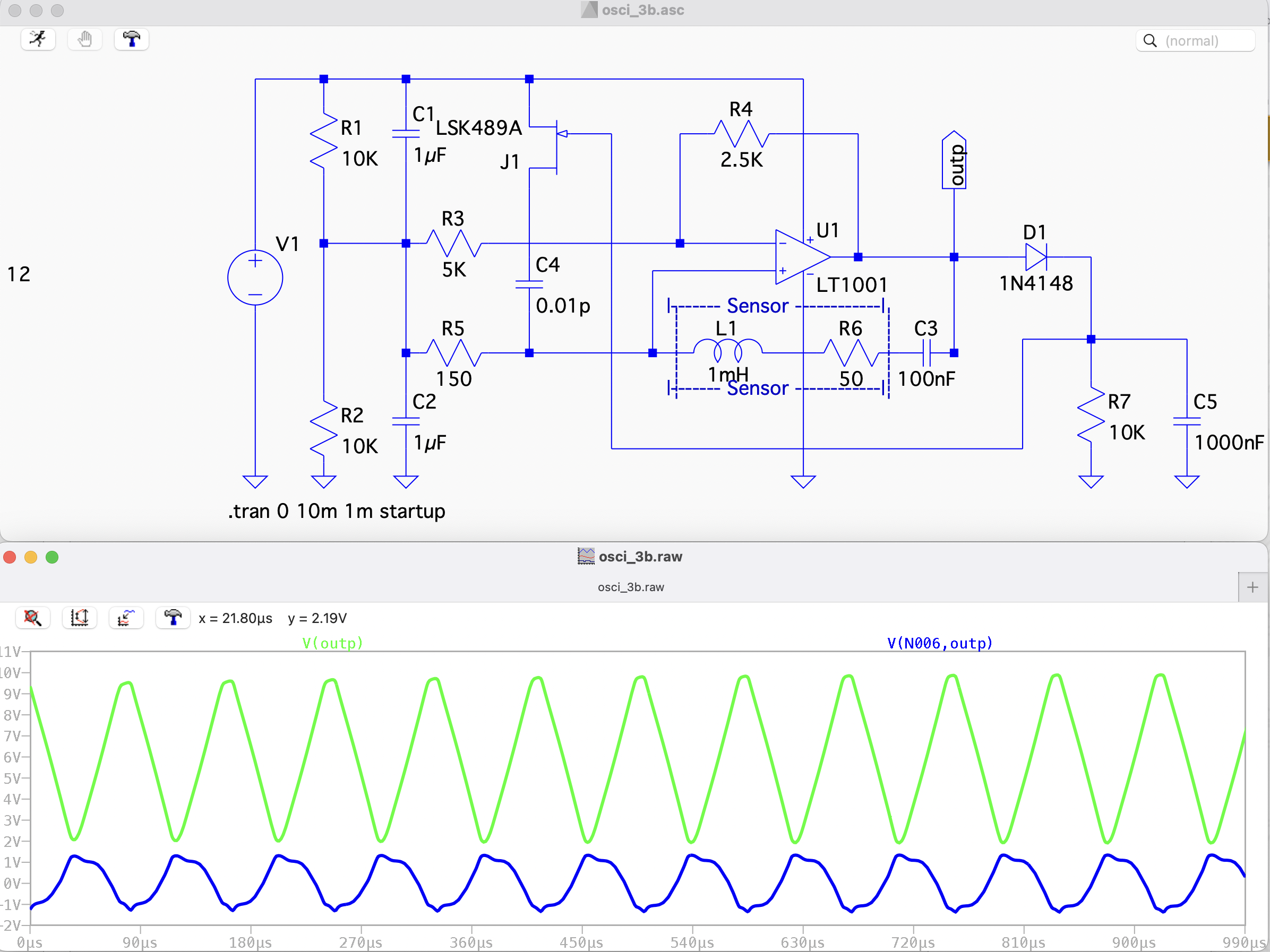
Schaltplan und Oszilloskop-Simulation eines Oszillators
osci_3b.asc LSK489A J1 R1 10K C1 1µF R4 2.5K U1 outp D1 1N4148 R3 5K C4 0.01p R5 150 R2 10K C2 1µF L1 1mH Sensor R6 50 C3 100nF R7 10K C5 1000nF .tran 0 10m 1m startup osci_3b.raw x = 21.80µs y = 2.19V V(outp) V(N006, outp) 0µs 180µs 270µs 360µs 450µs 540µs 630µs 720µs 810µs 900µs 990µs
in „Induktiver Positionssensor - Fragen dazu“ · Mikrocontroller und Digitale Elektronik · · Screenshots
-
PDF
mc12.pdf
0 IRFB3207 3.3mOhm 0 R5 R14 X13 X10 5 R4 20 a c V2 MBRF20200 X12 R11 5 X4 ua1 10m X9 R13 D2 D1 L1 3.76u 0 CMP OUT1 C3 0.674u L3 uc1 uc2 um ua2 0 FB OUT2 b R7 3.37u 900 R17 IMAX GND 2m R8 L2 D4 D3 ua u2 u1 X11 0 0 100u ic=165 C2 R10 R15 5 5 47 R2
in „Schaltungsanalyse Microcap“ · Analoge Elektronik und Schaltungstechnik ·
-
 Bild
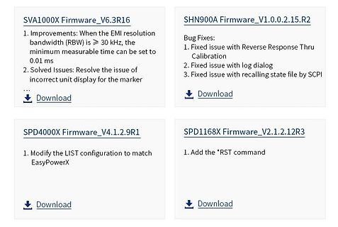
Firmware-Download-Übersicht für Messgeräte
0.01 ms 2. Solved Issues: Resolve the issue of incorrect unit display for the marker Download SHN900A Firmware_V1.0.0.2.15.R2 Bug Fixes: 1. Fixed issue with Reverse Response Thru Calibration 2. Fixed issue with log dialog 3. Fixed issue with recalling state file by SCPI Download SPD4000X Firmware_V4.1.2.9R1
in „Raspberry Pi CM0 bei AliExpress, STMicroelectronics mit PX5, neue Messtechnik und AI-Assistenten“ · Mikrocontroller und Digitale Elektronik · · Screenshots
-
PDF
L2418A_Ersatzteilliste.pdf
ontpasétéprévues,ilfaut Pedidos,consultasdepreciosydeplazosdeentregaqueafecten s’adresser par écrit à KH-PR/FEG1. a repuestos no planificados tienen que dirigirse a KH-PR/FEG1 Pour ces pièces, il faut s’attendre à des délais de livraison plus por escrito. longs. Hay que contar con plazos de entrega más
in „Ladegerät reparieren / Bosch L2418“ · Analoge Elektronik und Schaltungstechnik ·
-
PDF
bc547.pdf
. Max. Units CBO Collector Cut-off Current VCB=30V, E =0 15 nA hFE DC Current Gain VCE=5V, C =2mA 110 800 VCE(sat) Collector-Emitter Saturation VoltIC=10mA, B =0.5mA 90 250 mV IC=100mA, B =5mA 200 600 mV VBE(sat) Base-Emitter Saturation Voltage IC=10mA, B =0.5mA 700 mV I =100mA, I =5mA 900 mV C B VBE(on) Base-Emitter On Voltage VCE=5V, C =2mA 580 660 700 mV VCE=5V, C =10mA 720 mV T Current Gain Bandwidth Product VCE=5V, C =10mA, f=100MHz 300 MHz Cob Output Capacitance VCB=10V
in „Mikrocontrollerboard: Funktioniert das?“ · Mikrocontroller und Digitale Elektronik ·
-
PDF
bc547.pdf
. Max. Units CBO Collector Cut-off Current VCB=30V, E =0 15 nA hFE DC Current Gain VCE=5V, C =2mA 110 800 VCE(sat) Collector-Emitter Saturation VoltIC=10mA, B =0.5mA 90 250 mV IC=100mA, B =5mA 200 600 mV VBE(sat) Base-Emitter Saturation Voltage IC=10mA, B =0.5mA 700 mV I =100mA, I =5mA 900 mV C B VBE(on) Base-Emitter On Voltage VCE=5V, C =2mA 580 660 700 mV VCE=5V, C =10mA 720 mV T Current Gain Bandwidth Product VCE=5V, C =10mA, f=100MHz 300 MHz Cob Output Capacitance VCB=10V
in „Displaybeleuchtung mit PWM dimmen“ · Mikrocontroller und Digitale Elektronik ·
-
PDF
18481_BC547_data.pdf
. Typ. Max. Units CBO Collector Cut-off Current VCB=30V, E =0 15 nA hFE DC Current Gain VCE=5V, C =2mA 110 800 VCE(sat) Collector-Emitter Saturation VoltIC=10mA, B =0.5mA 90 250 mV IC=100mA, B =5mA 200 600 mV VBE(sat) Base-Emitter Saturation Voltage IC=10mA, B =0.5mA 700 mV I =100mA, I =5mA 900 mV C B VBE(on) Base-Emitter On Voltage VCE=5V, C =2mA 580 660 700 mV VCE=5V, C =10mA 720 mV T Current Gain Bandwidth Product VCE=5V, C =10mA, f=100MHz 300 MHz Cob Output Capacitance VCB=10V
in „NPN Transistor Kennlinie verstehen“ · Analoge Elektronik und Schaltungstechnik ·
-
PDF
BC547.pdf
. Typ. Max. Units CBO Collector Cut-off Current VCB=30V, E =0 15 nA hFE DC Current Gain VCE=5V, C =2mA 110 800 VCE(sat) Collector-Emitter Saturation VoltIC=10mA, B =0.5mA 90 250 mV IC=100mA, B =5mA 200 600 mV VBE(sat) Base-Emitter Saturation Voltage IC=10mA, B =0.5mA 700 mV I =100mA, I =5mA 900 mV C B VBE(on) Base-Emitter On Voltage VCE=5V, C =2mA 580 660 700 mV VCE=5V, C =10mA 720 mV T Current Gain Bandwidth Product VCE=5V, C =10mA, f=100MHz 300 MHz Cob Output Capacitance VCB=10V
in „Arduino. Transistor schaltet nicht richtig“ · Mikrocontroller und Digitale Elektronik ·
-
PDF
BC547B.pdf
. Typ. Max. Units CBO Collector Cut-off Current VCB=30V, E =0 15 nA hFE DC Current Gain VCE=5V, C =2mA 110 800 VCE(sat) Collector-Emitter Saturation VoltIC=10mA, B =0.5mA 90 250 mV IC=100mA, B =5mA 200 600 mV VBE(sat) Base-Emitter Saturation Voltage IC=10mA, B =0.5mA 700 mV I =100mA, I =5mA 900 mV C B VBE(on) Base-Emitter On Voltage VCE=5V, C =2mA 580 660 700 mV VCE=5V, C =10mA 720 mV T Current Gain Bandwidth Product VCE=5V, C =10mA, f=100MHz 300 MHz Cob Output Capacitance VCB=10V
in „Basiswiderstand richtig berechnet?“ · Analoge Elektronik und Schaltungstechnik ·
-
PDF
BC547_datasheet.pdf
. Typ. Max. Units CBO Collector Cut-off Current VCB=30V, E =0 15 nA hFE DC Current Gain VCE=5V, C =2mA 110 800 VCE(sat) Collector-Emitter Saturation VoltIC=10mA, B =0.5mA 90 250 mV IC=100mA, B =5mA 200 600 mV VBE(sat) Base-Emitter Saturation Voltage IC=10mA, B =0.5mA 700 mV I =100mA, I =5mA 900 mV C B VBE(on) Base-Emitter On Voltage VCE=5V, C =2mA 580 660 700 mV VCE=5V, C =10mA 720 mV T Current Gain Bandwidth Product VCE=5V, C =10mA, f=100MHz 300 MHz Cob Output Capacitance VCB=10V
in „Frage zur Berechnung von Basiswiderstand BC547B mit Motor 5V“ · Analoge Elektronik und Schaltungstechnik ·
-
PDF
sfh3310.pdf
S = f (λ ) I = f (E ), V = 5 V C = f (V ) rel PCE V CE CE CE 100 OHF00851 1000 OHF00852 4.0 pF % µA 3.5 I C S rel80 PCE CE 3.0 70 100 2.5 60 50 2.0 V λ 40 1.5 30 10 1.0 20 0.5 10 0.0 0 1 1E-03 1E-02 1E-01 1E+00 1E+01 1E+02 400 500 600 700 800 900 nm 1100 1 10 100 lx 1000 V V λ E V CE Collector-Emitter
in „Suche Ersatztyp zu SFH3310“ · Mikrocontroller und Digitale Elektronik ·
-
PDF
SFH309FA.pdf
nm Photocurrent 2 E e= 0.5 mW/cm , VCE = 5 V IPCE 0.4 ... 0.8 0.63 ... 1. 1.0 ... 2.0 1.6 ... 3.2 mA SFH 309: 25 E v= 1000 Ix, Normlicht/ IPCE 1.5 4.5 7.2 mA standard light A,V CE= 5 V 2.8 Anstiegszeit/Abfallzeit t,t 5 6 7 8 s r f Rise and fall time IC= 1 mA, V CC= 5 V, R = 1 k L Kollektor-Emitter-
in „Fototransistor oder Fotodiode?“ · Mikrocontroller und Digitale Elektronik ·
-
PDF
vcnl4040.pdf
specified) Axis Title 100 10000 90 ALS-CH PS-CH ) 80 ( 70 u 1000 e t 60 e e l O l l d d 50 s d 2 i 40 1 2 a r 30 100 o N 20 10 0 10 400 500 600 700 800 900 1000 λ - Wavelength (nm) 2nd line Fig. 4 - Normalized Spectral Response Fig. 7 -DDvs.Temperature Fig. 5 - Forward Current I= f (V ) Fig. 8 - ALS View Angle
in „VNCL4040 Vorwiderstand?“ · Mikrocontroller und Digitale Elektronik ·
-
PDF
Reflexlichtschranke_SFH9201.pdf
Max.timein (Iron temp.) stand. 020 (solderbath) peak zone (package peak zone temp.) SFH 9201 4 n. a. — 245°C 10 sec. n.a. Bitte Verarbeitungshinweise für SMT-Bauelemente beachten! Please observe the handling guidelines for SMT devices! Kennwerte ( T = 25 °C) A Characteristics Bezeichnung Symbol Wert
in „günstige Lichtschranke“ · Mikrocontroller und Digitale Elektronik ·
-
Datei
Monitorhalterung2_2.ino
Value = analogRead(S4); _S5_Value = analogRead(S5); } // Achse Wand if ((_S1_Value < 250) && (_Achse_A_1_Value == 1)) //Achse Wand ausfahren (links) { digitalWrite(K1_A_0, LOW); digitalWrite(K4_A_1, LOW); } if ((_S1_Value > 750 && _S1_Value < 900 && _Achse_A_0_Value == 1)) //Achse Wand einfahren (rechts) { digitalWrite(K1_A_0, LOW); digitalWrite(K4_A_1, HIGH); } if ((_S1_Value > 251 && _S1_Value < 749) || (_Achse_A_1_Value == 0 && _S1_Value < 250) || (_Achse_A_0_Value == 0 && _S1_Value > 750)) //Achse Wand Stopp { digitalWrite
in „Falsche Analogwerte im Seriellen Monitor“ · Mikrocontroller und Digitale Elektronik ·
-
PDF
00037525_0_SPL_PL90_3.pdf
λ T A= 25 °C, Popt= 75 W) 12 OHF0056120 OHF00565 1.00 V F V W Popt Ι rel 10 100 0.75 8 80 6 60 0.50 4 40 0.25 2 20 0 0 0 0 10 20 30 40 A 50 880 890 900 910 nm 930 IF λ Far-field distribution parallel to junction
-
PDF
e1022.pdf
the user. exceptional performance of the - Easy to integrate best-selling ScanPlus 1800Vista™ into a very compact,industry- Integrating an OEM module has standard form factor: never been so easy. - Unique reading performance Designing a new product? The E1022 is easy to control.It The E1022 can read
in „[V] 2 Honeywell Intermec 1D Barcodescannermodule E1022“ · Markt ·
-
Datei
20221003a-Einspeise.ino
/ UVLO Batterie mit Hysterese int battpin = A0; unsigned long battist; unsigned long battstart; int battwerthoch = 464; // 1023*11V*39K:(150K + 39K):5V int battwerttief = 378; // 1023*9V0*39K:(150K + 39K):5V int battwertovlo = 676; // 1023*16V*39K
-
PDF
zmm33.pdf
1 is a diode, operated in forward. The cathode, indicated by a ring, is to be connected to the negative pole. Die ZPD 1 ist eine in Durchlafl betriebene Einzelchip-Diode. Die durch den Ring gekennzeichnete Kathode
in „Vom Testaufbau in die Wirklichkeit“ · Mikrocontroller und Digitale Elektronik ·
-
PDF
High-Voltage-PCDesign.pdf
dielectric rating and increase the effects of corona aging. 8 FR4 has an initial dielectric rating of 800-900 Volts per mil but due to aging effects, a more realistic value is only 300 Volts. I strongly suggest you manufacture your prototype boards with a few combinations of material thickness. One board I
-
PDF
FS1273_NEU_R8b_High_Power_DPM.pdf
+OUT D Trafobeschaltunggezeigtfür120VAC,60HZ R8B D 0 30V,0.01 2A 15FR200E 1N5402 R4 R4B Spannungsvergleichverstärker VREF+ NETZSCHALTER 10R 10R Bu1 GL1 R9 NEU F1 C16 DPM- L T1 100n KBL02 470K 1A SB Q2 Q2B R5 beinflußt den Neu C19 CURRENTMETER(0 200mV) CURRENTSET E
in „Labornetzgerät als Projekt“ · Analoge Elektronik und Schaltungstechnik ·
-
PDF
mosfet_K3673.pdf
IGSS V GS=±30V V DS=0V 100 nA Drain-source on-state resistance RDS(on) ID=5A V GS=10V 0.91 1.18 Ω gfs S Forward transcondutance ID=5A VDS=25V 5 9.5 Input capacitance Ciss V DS=25V 900 1350 pF Output capacitance Coss V GS=0V 140 210
in „Mosfet K3673 01“ · Analoge Elektronik und Schaltungstechnik ·
-
PDF
TUNER_2000_DHC.pdf
Select MasterPrescaler (7) (6) Factor Out Out (8) (5) TUNE MASTER = 0...30 V DC Band Select = 0 V Band A (80 ... 160 MHz) Band Select = 5 V Band B (160 ... 500 MHz) Band Select = 12 V Band C (430...900 MHz) Scale Factor Input = Open by 64 Scale Factor Input = Vcc by 128 Scale Factor Input = GND by 256 OUTP
in „Anschlussbelegung Tuner 2000 DHC mit TDA5330T“ · HF, Funk und Felder ·
-
PDF
BTS_100_High_Side.pdf
leakage current I GSS VGS = — 20 V,V DS= 0 Tj= 25 °C — — 10 — 100 nA Tj= 150 °C — — 2 — 4 A Drain-source on-state resistance R DS(on) VGS = — 10 V, D = — 5 A — 0.25 0.3 Dynamic Characteristics Forward transconductance gfs S VDS ≥ 2 ×ID ×R DS(on)maD = — 5 A 1.5 2.3 4.0
in „Motorsteuerung mit kollektorschaltung“ · Mikrocontroller und Digitale Elektronik ·
-
PDF
bts100.pdf
leakage current I GSS VGS = — 20 V,V DS= 0 Tj= 25 °C — — 10 — 100 nA Tj= 150 °C — — 2 — 4 A Drain-source on-state resistance R DS(on) VGS = — 10 V, D = — 5 A — 0.25 0.3 Dynamic Characteristics Forward transconductance gfs S VDS ≥ 2 ×ID ×R DS(on)maD = — 5 A 1.5 2.3 4.0
in „BTS 100 Ersastzlösung“ · Mikrocontroller und Digitale Elektronik ·
-
PDF
Schaltplan_Cocktailmaschine.pdf
3.3 Relais_12V Relais_24V / 3.6 Arduino_5V_2 -Relaiskarte_1 /6.1 VCC IN1 IN2 IN3 IN4 IN5 IN6 IN7 IN8 A1 A1 A1 A1 A1 A1 A1 A1 -K1 -K2 -K3 -K4 -K5 -K6 -K7 -K8 A2 A2 A2 A2 A2 A2 A2 A2 GND Arduino_GND_2 + + + + + + + + 3.6 + + + + + + + + M M M M M M M M -M1 -M2 -M3 -M4 -M5 -M6 -M7 -M8 - - - - - - - - - -
in „Cocktailmaschine für Anfänger“ · Mikrocontroller und Digitale Elektronik ·
-
PDF
71006566_de.pdf
2 8-9A1 Messystem f. X,Y-Achse LS 403 C 520mm Heidenhain 27.071735 1 10A1 Messystem f. Z-Achse LS 403 C 420mm Heidenhain 27.071734 1 19A1-2 Steuerung CNC 232 Heidenhain 93.000364 1 28A1 Platine EK 10/SM Murr
in „CRT Monitor gegen VGA Monitor tauschen“ · Analoge Elektronik und Schaltungstechnik ·
-
Datei
logFile.txt
/usr/X11R6/lib/modules/extensions/libGLcore.a Skipping "/usr/X11R6/lib/modules/extensions/libGLcore.a:m_debug_clip.o": No symbols found Skipping "/usr/X11R6/lib/modules/extensions/libGLcore.a:m_debug_norm.o": No symbols found Skipping "/usr/X11R6
-
PDF
MMS8550.pdf
• Capable of 0.3Watts(Tamb=25 C) of Power Dissipation. Plastic-Encapsulate • Collector-current 0.5A • Collector-base Voltage 40V Transistor O O • Operating and storage junction temperature range: -55 C to +150 C • Marking : 2TY • Epoxy meets UL 94 V-0 flammability rating • Moisure Sensitivity Level 1 SOT-23 A D ElectricalCharacteristics@25CUnlessOtherwiseSpecified C Symbol Parameter Min Max Units C B OFFCHARACTERISTICS V(BR)CBO Collector-Base Breakdown Voltage 40 --- Vdc (C =100uAdc, E =0) B E F E V(BR)CEO
in „Transistor Schalter“ · Analoge Elektronik und Schaltungstechnik ·
-
PDF
tps78001.pdf
, V VSET = 1.2V, V OUT = 2.2V TPS780330220 TPS780330220 1000 T = +125°C 1000 T = +125°C 900 J 900 J 800 800 T J +85°C 700 700 TJ= +85°C A 600 A 600 ( ( N500 N 500 IG400 IG 400 300 300 TJ= +25°C TJ= -40°C TJ= +25°C T J -40°C 200 200 100 100 0 0 2.7 3.2 3.7 4.2 4.7 5.2 5.7 2.7 3.2 3.7 4.2 4.7
in „Ultra Low Power Versorgung aus Batterie, 3,3V und 5V“ · Analoge Elektronik und Schaltungstechnik ·
-
 Bild
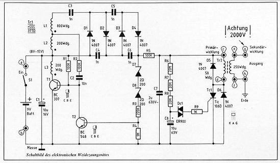
Schaltplan eines elektronischen Weidezaungerätes
D6 1N4007 D8 ZD 630V T2 BC 548 C B E R3 220K R4 1M C8 10u 9V Batt. 10u 16V 1K R9 Dc1 1N106D Tic ER900 Masse K A G Schaltbild des elektronischen Weidezaungerätes
in „Weidezaun gegen Schnecken mit Netztrafo und Rohr DN160 für Hobbygärtner“ · Projekte & Code · · Schaltpläne
-
Datei
Beispiel.txt
#define Eingang 0 // Pin5 ist Analogeingang A0 -> da muss ich dann die 0 im Programm verwenden?! #define Ausgang1 0 #define Ausgang2 1 #define Grenze1 450 // maximaler Wert: 1048 #define Grenze2 750 #define Grenze3 900 void setup() { // put your
in „Digispark Analogeingang verwenden“ · Mikrocontroller und Digitale Elektronik ·
-
PDF
isec05poster_pq11_a3.pdf
/ Hz 10 The largest C g ratio we found: BF862 TRACE A:Ch1 PSD TRACE A MarkerD 50 000.0 Hz 44.283 nVrms/rtHz Not promising /div g m 85AY* = Vrms/rtHz600 000 Hz 432.41 nVrms/rtHz 115 Y* = Vrms/rtHz T = 5.5 K, Z = 4.2 kΩ @ 10 MHz (theory) dB* dB* n n Bias
in „Meßverstärker für 1/f-Rauschen 0.1 - 10 Hz“ · Analoge Elektronik und Schaltungstechnik ·
-
PDF
Disassembler8048_mc1981.pdf
,"MOV &R1/A"/A3,"MOVP A,&A",A5,CLR F1 420 DATA A7,CPL C,A8,"MOV RO,A",A9,"MOV R1,A",AA,"MOV R2,A",AB 430 DATA "MOV R3,A",AC,"MOV R4,A",AD,"MOV R5,A",AE 440 DATA "MOV R6,A",AF,"MOV R7,A",B5,CPL F1,C5,SEL RBO,C7 450
in „80C48 MCS48 Assembler“ · Mikrocontroller und Digitale Elektronik ·
-
PDF
JP7-T-family.pdf
using the Set Operating Mode command in SiRFdemo. During the subsequent background cycles or when a user requests a position update (the RESET_N has to be used) a reset is generated and a hot start will be typically performed which may take up to a maximum of 8 seconds. The receiver wakes up, computes
in „wo finde ich RX und TX an GPS-Maus SIRF II?“ · Mikrocontroller und Digitale Elektronik ·
-
PDF
Lenovo_Z50-70_NM-A273_ACLUA_MB_Rev0.3_schematic_.pdf
0402_5% R26 1 @ 2 0_0402_5% USB20_N4_CONN Touch Screen USB20_N5 4 3 USB20_N5_R +3VALW 3 2 4 3 CMM21T-900M-N_4P R27 1 @ 2 0_0402_5% 1 @ 1 D2 ForEMI USB20_P4 1 L13 @ 2 USB20_P4_CONN 2 AZC199-02S.R7G_SOT23-3 A 1 2 2 @ A AZ5215-01F_DFN1006P2E2 USB20_N4 4 4 3 3 USB20_N4_CONN 1 CMM21T-900M-N_4P ForEMI Security
in „Laptop defekt: Kommunikation EC - PCH - CPU“ · Mikrocontroller und Digitale Elektronik ·
-
PDF
AXP202_PMU.pdf
and Voltage AC-adaptor with voltage/current-limit o On-chip Coulometer and Fuelgauge with High (4.4V/900mA/500mA/100mA) Precision o Equivelent Resistance of Batter Power Path o Provide Various Power Management data such as less than 75mΩ Transient Power Consumption(mAor mW), • Fully Integrated PWM Charger
in „LilyGo T-Watch 2020 v1 Micropython“ · Mikrocontroller und Digitale Elektronik ·
-
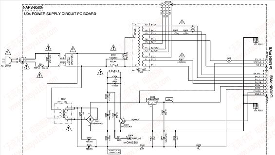
 Bild
Schaltplan eines Netzteil-PC-Boards
NAPS-9580 U04 POWER SUPPLY CIRCUIT PC BOARD JL504B P901 F901 F901A F901B L1 C902 472/250V NPN-3557 RELAY NPT-1467 T901 C904 223 1SS355 T902 NPT-1520 C905 223 D901 1SS355 D902 1SS355 D903 1SS355 C906 470/16V P904 223K C911 4.7/50V D911 UD235.19 C914 104Z R902 3.9K R903 1K C903 5V S-812C50AJA P903 J903 STBY+ B 2 S3 1 3.2 S3 2 GND 0 C900 to MAIN PWB R905 1(1W) R906 1(1W) R907 4.7(1/2W) S2 2.4 S2 4 S2 1.6 S3 1.4 S3 1.2 S3 1 CT2 2 S2 CT2 1 S1 1 S1 2 S1 1
in „Reparatur Onkyo CR-525“ · Analoge Elektronik und Schaltungstechnik · · Schaltpläne
-
PDF
BC1.2_FINAL.pdf
. Table 5-2. 3. Indicate thatCDP max and I DCP max limits of 5A come from USB 2.0, and are safety limits. Table 5-2 note 1. 4. Allow PDs to draw up to 1.5A during HS chirp and traffic. Remove previous limits of 560mA and 900mA which was based on HS common mode ranges
-
PDF
ET-Aufgaben.pdf
Gesamtwiderstand der Schaltung! Es sind R =25Ω, R =100Ω, R =22Ω, R =55Ω,3 4 R 56Ω, R =6Ω, R =207, R =400Ω8 R =900Ω. 9 205. Berechnen Sie die fehlenden Werte! (U =5V)1 206. Berechnen Sie I !5(φ =A0,5V) Stand 06.10.2021 Seite 31 von 75 Elektrotechnik - Aufgabensammlung 207. Berechnen Sie U 1 (I4=0,5A) 208. Berechnen
-
Datei
Singstar.java
0.5; for (int i = 0; i < sampleList.length / 2; i++) { double time = i * SECONDS_PER_SAMPLE; double a = f * time * 2 * Math.PI; sampleList[i] = amp * (Math.sin(a + 1.1) / 1 + Math.cos(a * 2 - 1.2) / 2 + Math.sin(a * 3 - 1.3) / 3 + Math.cos(a * 4 + 1.4) / 4); } for (int i = sampleList.length / 2; i < sampleList.length; i++) { double time = i * SECONDS_PER_SAMPLE; double a = f * time * 2 * Math.PI * HALFTONE_RATIO * HALFTONE_RATIO * HALFTONE_RATIO; sampleList[i] = amp * (Math.sin(a + 1.1) / 1 + Math.cos(a * 2 - 1.2) / 2 + Math.sin(a * 3 - 1.3) / 3 + Math.cos(a * 4 + 1.4
in „Stimm / Gesangsanalyse“ · Digitale Signalverarbeitung / DSP / Machine Learning ·
-
PDF
htfs200_800p_e_rev09.pdf
with a R L 10 kΩ Electrical data Primary nominal Primary current Type current rms measuring range PN(A) IPM(A) Features 200 ± 300 HTFS 200-P • Hall effect measuring principle 400 ± 600 HTFS 400-P • Galvanic
-
PDF
156408-da-01-en-IR_PHOTOTRANSISTOR_PT331C_PT333_3C__EVL.pdf
Characteristics (Ta=25℃) Parameter Symbol Condition Min. Typ. Max. Units Collector – Emitter IC=100μA BV CEO Ee=0mW/cm 2 30 --- --- V Breakdown Voltage IE=100μA Emitter-Collector BV ECO 2 5 --- --- V Breakdown Voltage Ee=0mW/cm I =2mA Collector-Emitter V C 2 --- --- V Saturation Voltage CE)(satEe=1mW/cm 0.4 Rise Time tr VCE5V --- 15 --- IC=mA μS Fall Time tf RL=1000Ω --- 15 --- 2 Collector Dark Current ICEO Ee=0mW/cm --- --- 100 nA V CE0V On State Collector Current Ee=1mW/cm 2 C(on) VCE5V 0.7 2.5 --- mA Wavelength of λp --- --- 940 --- nm
in „IR sichtbar machen - Schaltung so richtig?“ · Analoge Elektronik und Schaltungstechnik ·
-
PDF
WebenchReportsServlettps5450-02.pdf
V 7343-31 59mm2 IRMS= 900.0 mA 4. D1 Vishay-Semiconductor 50WQ10FNPBF 1 $0.41 VF@Io= 770.0 mV VRRM= 100.0 V DPAK 102mm2 5. L1 Wurth Elektronik eiSos 7443634700 1 $6.70 L= 47.0 µH DCR= 12.2 mOhm IND_WE-HCF 540mm2 6. Rfbb Vishay-Dale
-
Datei
sysreport.txt
23/2010 CPU: Topology: Dual Core model: Intel Core2 Duo T6600 bits: 64 type: MCP arch: Penryn rev: A L2 cache: 2048 KiB flags: lm nx pae sse sse2 sse3 sse4_1 ssse3 bogomips: 8799 Speed: 1200 MHz min/max: 1200/2200 MHz Core speeds (MHz): 1: 1200 2: 1200 Graphics: Device-1: NVIDIA G96M [GeForce 9600M
in „[v] Bastler-Laptop Asus X70IC Core2 Duo, ohne Akku, 4GB RAM, 20GB HDD, LinuxMint“ · Markt ·
-
PDF
Beschreibung_Batteriemonitor_BM-1000.pdf
wwww.roundsolutions.com Diagramme (erzeugt mit „OpenOffice Calc“): Akkuladung 1400 1300 1200 1100 1000 > 900 - 800 n 700 u 600 a L 500 400 300 200 100 0 Zeile 2Zeile 985Zeile 2196Zeile 3480Zeile 4764Zeile 6048Zeile 7331Zeile 8615Zeile 9899 Zeit ---> In diesem Diagramm ist der Ladevorgang für einen Lithium-Ionen
in „Telit GM862-Quad Problem“ · Mikrocontroller und Digitale Elektronik ·
-
PDF
ebay.pdf
Versand und Zahlungsmethoden Weiterempfehlen: Der Verkäufer ist für dieses Angebot verantwortlich. A Letzte Aktualisierung am 12:01:03 MEZ, 11. Mär. 2011 Alle Änderungen anzeigen Artikelmerkmale Zustand: Gebraucht: Artikel wurde bereits benutzt. Weitere Einzelheiten, z. B. genaue Beschreibung etwaiger
-
Datei
RFM12BPCmd.h
// bit 15 14 13 12 11 10 9 8 7 6 5 4 3 2 1 0 POR // 1 0 1 0 f11 f10 f9 f8 f7 f6 f5 f4 f3 f2 f1 f0 A680h #define CMD_SET_FREQ 0xA000 // [ f11..f0 ] -> Set operation frequency: // 433band: Fc=430+F*0.0025 MHz // 868band: Fc=860+F*0.0050 MHz // 915band: Fc=900+F*0.0075 MHz // Fc is carrier frequency and
in „Rfm12B 686Mhz Bascom Testprogramm.“ · HF, Funk und Felder ·
-
PDF
ChanSortBeispiel.pdf
European Telecommunications Satellite Organization 87 NHK WORLD-JAPANUnchecked11373 H Hotbird 6-9 318 900 533 5331 5331 27500 Eutelsat European Telecommunications Satellite Organization 88 UNINETTUNO UNIVERSITYked11013 H Hotbird 6-94511 12500 17718 1880 1880 29900 Sky ItaliSky Italia Spa. 89 Rai Scuola