-
Thread
NPN/Mosfet Schaltung - Funktioniert, aber gibt es Verbesserungen?
Betriebsspannung > garantiert? Ja. Hochohmig als Eingang ist zu erwarten. Sowohl das, aber auch ein Low-Ausgang machen R49 unnötig. Einzige Ausnahme wäre ein High-Ausgang während der Initialisierung. Sollte das jemals ein MC so machen, wäre das heftig unerwartet. Aber dann würde R49 auch nicht helfen
der typischen Schwankung der GS Kapazität mit ±100pF optimistisch angenommen und der Variation der Low Und High Pegel der Transistor Basis Ansteuerung kommt man auf eine Standardabweichung der Pulslänge von 1.3us (wegen Bauteiltoleranzen) Bei einer robusten Auslegung sollte man es so in etwa mit ±
-
Thread
Fast PWM (TCNT2)
automatisch. Das heißt für Clear on Compare Match: Bei Timer Counter == 0 -> OCR Pin geht auf High und bei Compare Match auf Low. Das heißt für Set on Compare Match: Bei Timer Counter == 0 -> OCR Pin geht auf Low und bei Compare Match auf High.
Compare Match ist das was man sich so allgemein von PWM vorstellt. Erste Phase der Periodendauer ist High und bei Compare Match, also Ende der eingestellten Duty-Dauer wechselt das Signal für den Rest der Periodendauer auf Low. Danach wiederholt sich der Spass.
-
 Bild
Bild
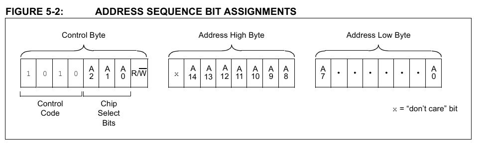
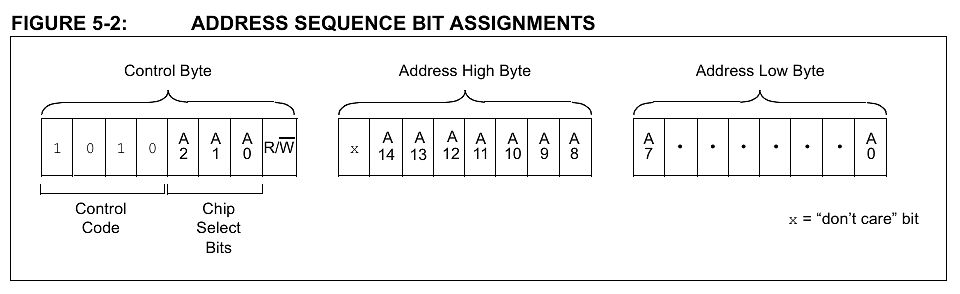
Bit-Zuweisung einer Adresssequenz
FIGURE 5-2: ADDRESS SEQUENCE BIT ASSIGNMENTS Control Byte Address High Byte Address Low Byte 1 0 1 0 A2 A1 A0 R/W Control Code Chip Select Bits x A14 A13 A12 A11 A10 A9 A8 A7 . . . A0 x = "don't care" bit
-
Thread
Injektorenströme messen
siehst Du nur die Hälfte oder bekommst einen Kurzschluß. DI-Injektoren werden sowohl von der HS (HighSide/Injector [+]) als auch LS (LowSide/Injector [-]) angesteuert. Die HS prägt die Ansteuerspannung ein (V_Boost [i.d.R. 55V-65V] oder V_Batt [Bornetzspannung], je nach Ansteuerphase), die LS übernimmt
es noch nicht. Frage ist nun, inwiefern Kurzschluss? Wenn ich dich richtig verstehe prägt der High-Side Treiber das positive potentila auf, der Low-Side Treiber schaltet Masse durch? Oder ein negatives Potential? Wenn man es differentiell messen muss bedeutet das ja es müsste ein negatives Potential
-
Thread
Hilfe bei Spannungsversorgung für DVB-S2-NIM
genau wie im Referenz-Design - Das Datenblatt sagt: "An output capacitor with large capacitance and low ESR is the best option. For most applications, a 22µF to 68µF ceramic capacitor is sufficient." - Auf dem PCB ist eh noch ein dritter Kondensator vorgesehen - Ich tendiere dazu, einfach noch einen
um den Ripple zu dämpfen. Im Datenblatt von meinen Linear-Reglern (LT3041) steht auch: "Ultra-high PSRR: 80 dB at 1 MHz" Das heißt doch eigentlich dass der Ripple ge-10^8-telt wird?! Oder verstehe ich da etwas grundsätzlich falsch? Ok, bei einem LM2576 steht da nichts von PSRR, insofern ist vielleicht
-
Thread
24V 1ms Impuls verlängern
ringspeicher länge 10 den gleitenden mittelwert zu berechenen, bzw auf integer level die summe, für digital high wäre die 10 und für low 0, fällt der wert unter 3 oder 4 ist low erkannt
Timer Interrupt mit 16 kHz einen Digitaleingang abfragen und in einen Ringbuffer der länge 16, für high einen 1 eintragen und für low eine 0, dann soll nach jeder Abfrage die gleitende Summe ermittelt werden, d.h. von der Summe den ältesten Wert aud dem Ringbuffer entfernen und den aktuellen dazuaddieren
-
Thread
Verpolungsschutz beidseitig mit 2 MOSFETs
Stefan P. schrieb im Beitrag #7894410: > aber ich habe bisher immer nur Schaltungen mit HighSide-Trennung > gesehen. Dann schau mal da und baue zu dieser "üblichen" diese P-Kanal-High-Side-Variante die N-Kanal-Low-Side-Variante mit dazu. - http://www.lothar-miller.de/s9y/archives/45-Verpolschutz.html
dass eine der beiden Varianten als Verpolschutz reicht. Denn die Ersatzschaltung der N+P-Kanal-High+Low-Side-Variante sieht so aus: [pre] o----->|----. | Last | o-----|<----' [/pre] Und nach den Gesetzen der Reihenschaltung darf ich daraus ungestraft sowas
-
Thread
Neuer dsPIC mit besserem ADC, ESP32-C61 in Serienfertigung, NFC 15 uvam
listet Microchip folgende Verbesserungen auf: [c] The dsPIC33AK512MPS family delivers precise, high-speed control through industry-leading 78 ps high-resolution Pulse Width Modulations (PWMs) and low-latency 40 Msps ADCs, enabling fast and accurate control loops essential for optimizing the performance
dsPIC33AK512MPS devices include advanced security features, an integrated touch controller and a high pin count of up to 128 pins. The dsPIC33AK512MC family is designed to offer low-latency, 40 Msps ADCs and 1.25 ns PWM resolution, providing a feature- and cost-optimized solution for multi-motor control
-
Thread
Arduino: page-write in I2C eeprom verliert sporadisch ein Byte
Buffer max size nibble = text2hex(Serial.read()); // read and convert 1. char = high nibble hi = nibble; // High nibble nibble = text2hex(Serial.read()); // read and convert 2. char = low nibble lo = nibble;
unterhalb der Zeilen [c] nibble = text2hex(Serial.read()); // read and convert 1. char = high nibble hi = nibble; // High nibble nibble = text2hex(Serial.read()); // read and convert 2. char = low nibble lo = nibble; val = hi<<4 | lo;
-
 Bild
Bild
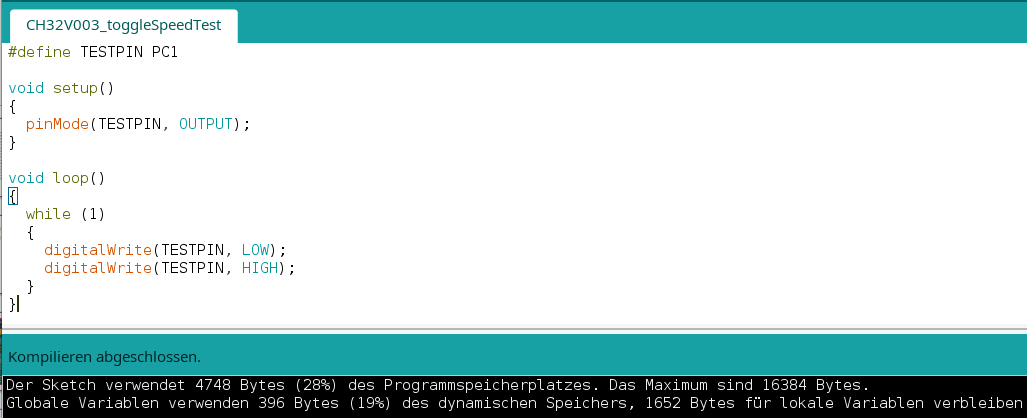
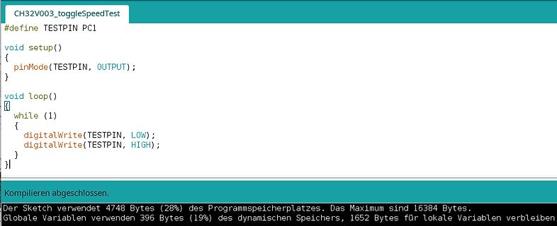
Arduino Code und Kompilierinformationen
TESTPIN PC1 void setup() { pinMode(TESTPIN, OUTPUT); } void loop() { while (1) { digitalWrite(TESTPIN, LOW); digitalWrite(TESTPIN, HIGH); } } Kompilieren abgeschlossen. Der Sketch verwendet 4748 Bytes (28%) des Programmspeicherplatzes. Das Maximum sind 16384 Bytes. Globale Variablen verwenden 396 Bytes (
-
Thread
Arduino CH32V003
Allows atomic setting or resetting of GPIOC output pins. // Write '1' to bit n (0-15) to set PCn high; write '1' to bit n+16 (16-31) to set PCn low. // Example: GPIOC_BSHR = (1 << 1); // Set PC1 high // GPIOC_BSHR = (1 << (1+16)); // Set PC1 low void setup() { // Enable GPIOC
Beitrag #7894401: > Wieviel davon braucht der Sprung? Sieht man doch ganz gut auf dem Oszi. 1 Takt High, 1 Takt Low, 2 Takte für den Sprung. Due könntest auch in der Schleife mehrere High/Low wechsel einbauen und dann siehst du auf dem Oszi die einzelnen zeiten etwas besser.
-
Thread
Arduino UNO => Takt und serielle Daten erzeugen
Wochen. [c] void send(uint8_t addr_cmd, uint8_t *data, size_t length) { digitalWrite(cs_pin, LOW); send_byte(addr_cmd); for (size_t i=0; i<length; i++) send_byte(data[i]); digitalWrite(cs_pin, HIGH); } void send_byte(uint8_t data) { for (uint8_t i=0; i<8; i++) { digitalWrite(clk_pin, LOW); digitalWrite(data_pin, data & 1 ? HIGH : LOW); data >>= 1; digitalWrite(clk_pin, HIGH); } } [/c]
-
 Bild
Bild
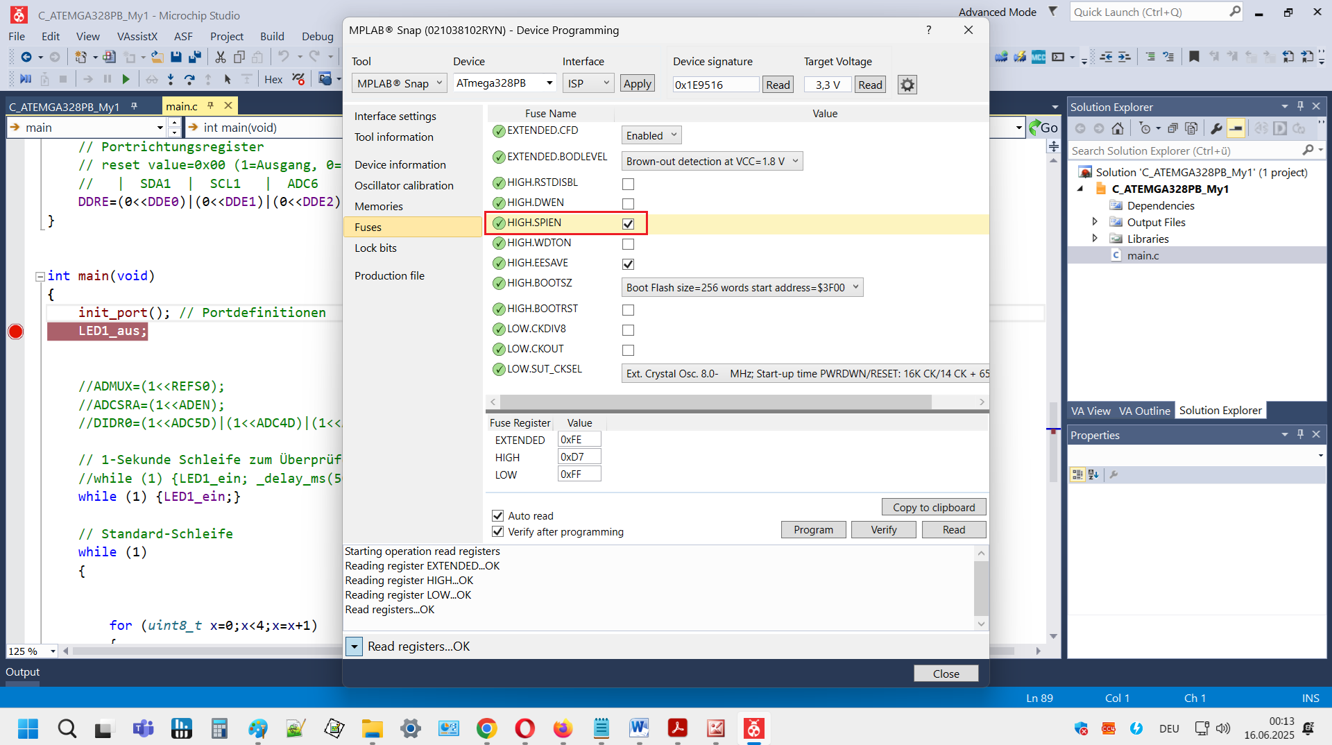
Software-Interface zur Programmierung eines ATmega328PB Mikrocontrollers
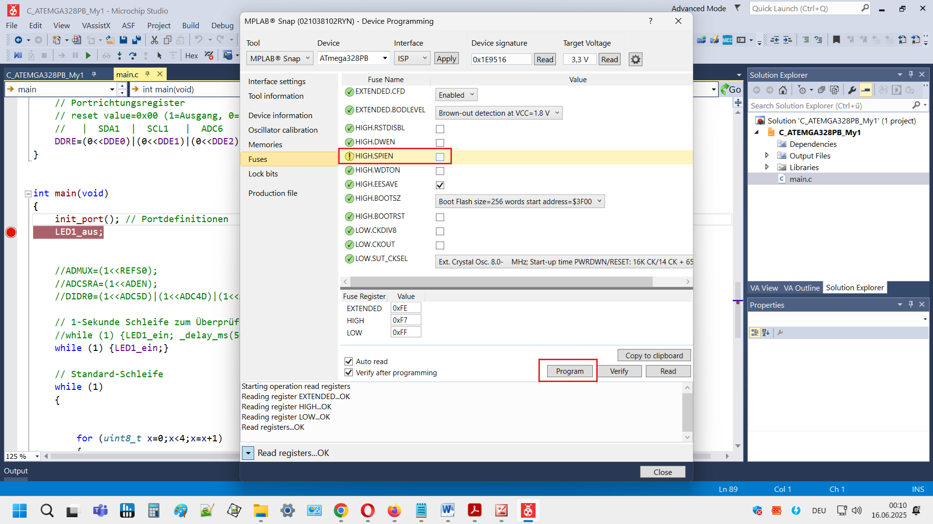
Programming Device signature: 0xE9516 Target Voltage: 3,3 V Interface: ISP Fuses: EXTENDED: BODLEVEL HIGH: SPIEN LOW: CKDIV8 Lock bits Program file main.c ATmega328PB

-
 Bild
Bild
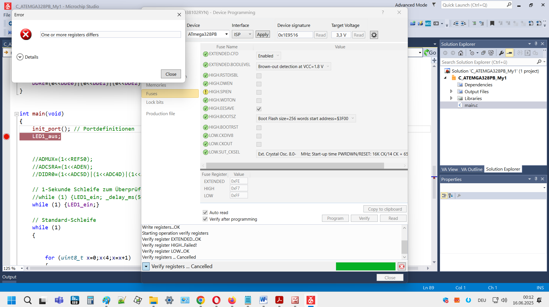
Microchip Studio Fehlermeldung beim Programmieren eines ATmega328PB
ATmega328PB Interface: ISP Device signature: 0x1E9516 Target Voltage: 3,3 V Fuses: EXTENDED, BOOLEVEL, HIGH, SPIEN, HIGH, WOTON, LEASAVE, BOOTSZ, LOW, CKDIV, LOW, CKOUT, LOW, SUT_CKSEL Verify registers... Cancelled

-
 Bild
Bild
Microchip Studio Device Programming Fenster
calibration Memories Fuses Lock bits Production file EXTENDED, BODLEVEL Brown-out detection at VCC= 1.8 V HIGH, SPIEN HIGH, WDTON HIGH, BOOTSR HIGH, CKOUT LOW, CKDIV LOW, CKOUT LOW, SUT, CKSEL Program Verify main.c

-
 Bild
Bild
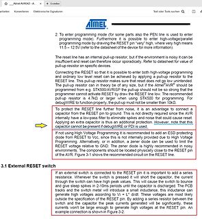
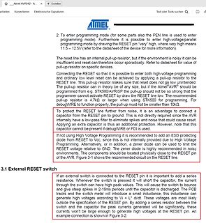
Ausschnitt aus einem Datenblatt zum Atmel AVR RESET Pin
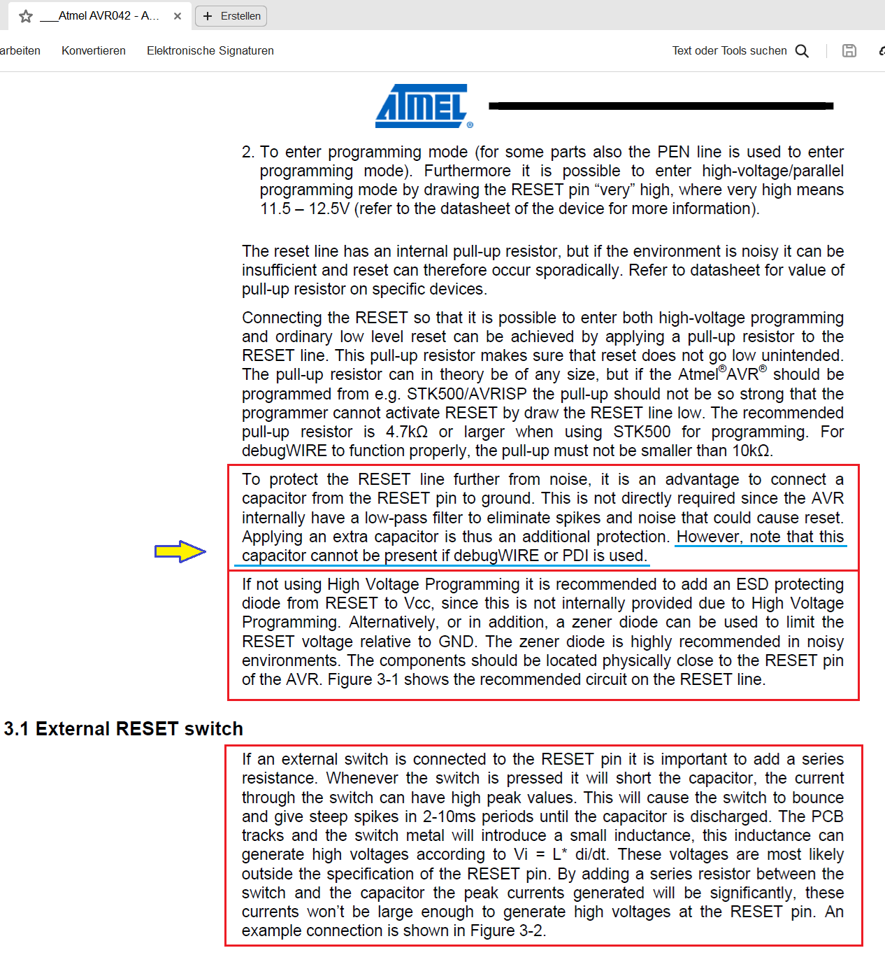
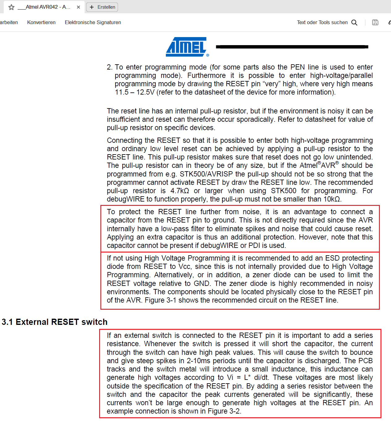
some parts also the PEN line is used to enter programming mode). Furthermore it is possible to enter high-voltage/parallel programming mode by drawing the RESET pin "very" high, where very high means 11.5 - 12.5V (refer to the datasheet of the device for more information). Connecting the RESET so that it is possible to enter both high-voltage programming and ordinary low level reset can be achieved by applying a pull-up resistor to the RESET line. This pull-up resistor makes sure that reset does not go low unintended. The pull-up
-
Thread
0..20 mA Analogeingang - wie?
digitale Signale: Linearität bei analogen Signalen (besonders wenn galvanische Trennung). Strompegel (High und Low) für digitale Signale. Umschaltung des Mikrocontroller-Eingangs analog/digital. So, wahrscheinlich habe ich noch was vergessen. Bevor das Gejammer los geht der TS hat nach "universell" gefragt
-
 Bild
Bild
Ausschnitt aus einem Atmel AVR Datenblatt
some parts also the PEN line is used to enter programming mode). Furthermore it is possible to enter high-voltage/parallel programming mode by drawing the RESET pin "very" high, where very high means 11.5 - 12.5V (refer to the datasheet of the device for more information). The reset line has an internal
-
Thread
AMD-AI-Keynote, Amper heruntergeskillt, PCIe 7.0 und AI-Ethernet
for testing the latest high-speed digital interfaces. The MM5622 system-in-package (SiP) solution fully integrates a driver, charge pump, and 12 high performance switch channels, offering significant board footprint reduction
its photo pixels, each measuring 56 µm × 600 µm. This new pixel geometry provides significantly higher contrast and signal yield in low light conditions. The latter also enables shorter measurement times. At the same time, the increased height of the pixels allows larger position tolerances during installation
-
 Bild
Bild
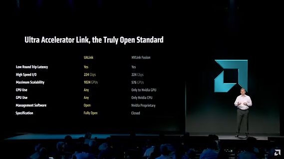
Präsentation Ultra Accelerator Link Vergleich mit NVLink Fusion
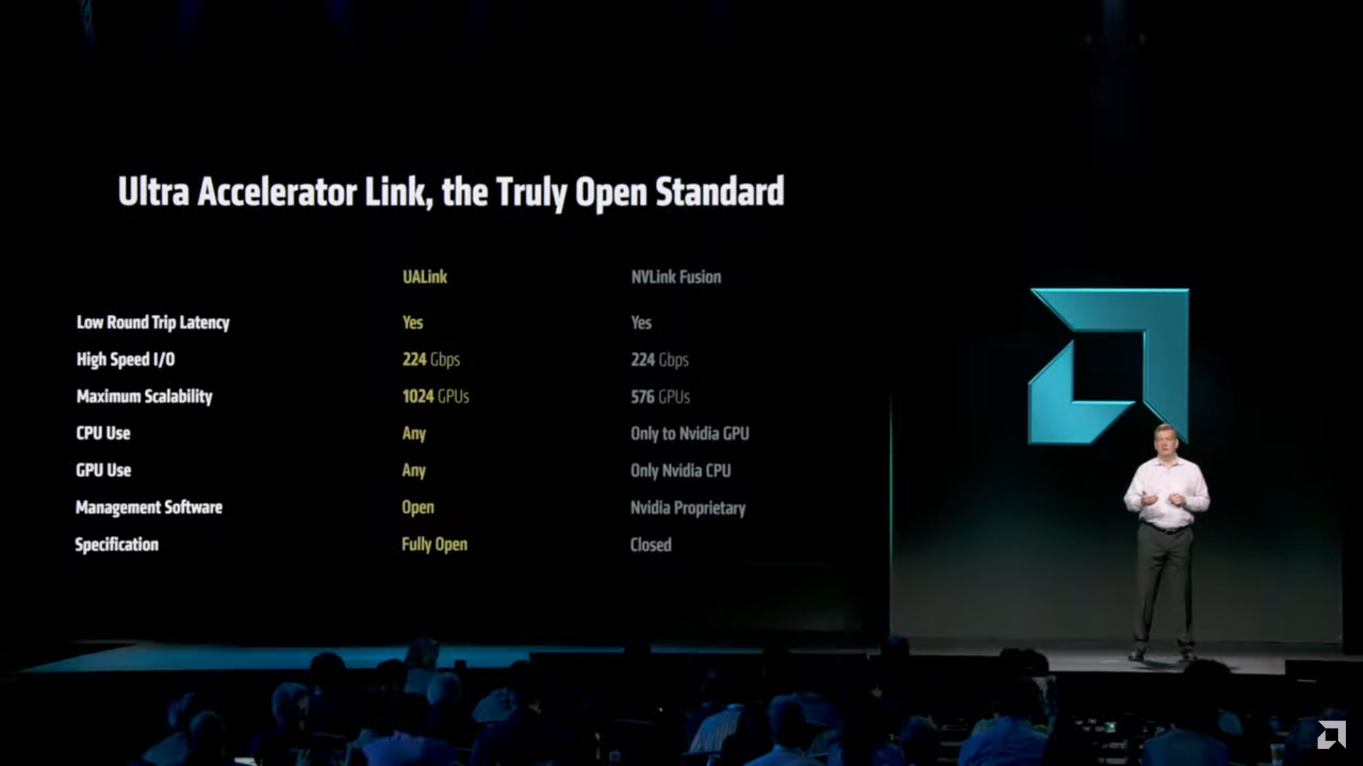
Ultra Accelerator Link, the Truly Open Standard UALink NVLink Fusion Low Round Trip Latency Yes Yes High Speed I/O 224 Gbps 224 Gbps Maximum Scalability 1024 GPUs 576 GPUs CPU Use Any Only to Nvidia GPU GPU Use Any Only Nvidia CPU Management Software Open Nvidia Proprietary
-
 Bild
Bild
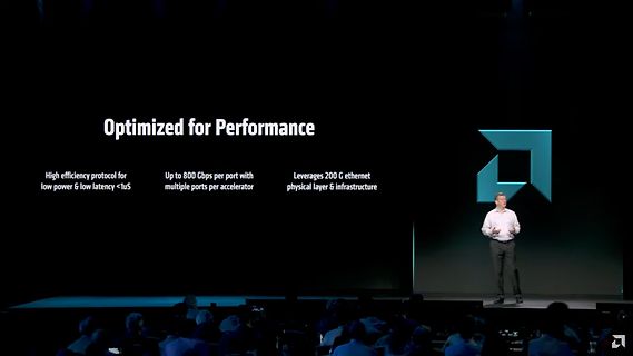
Präsentation auf einer Bühne
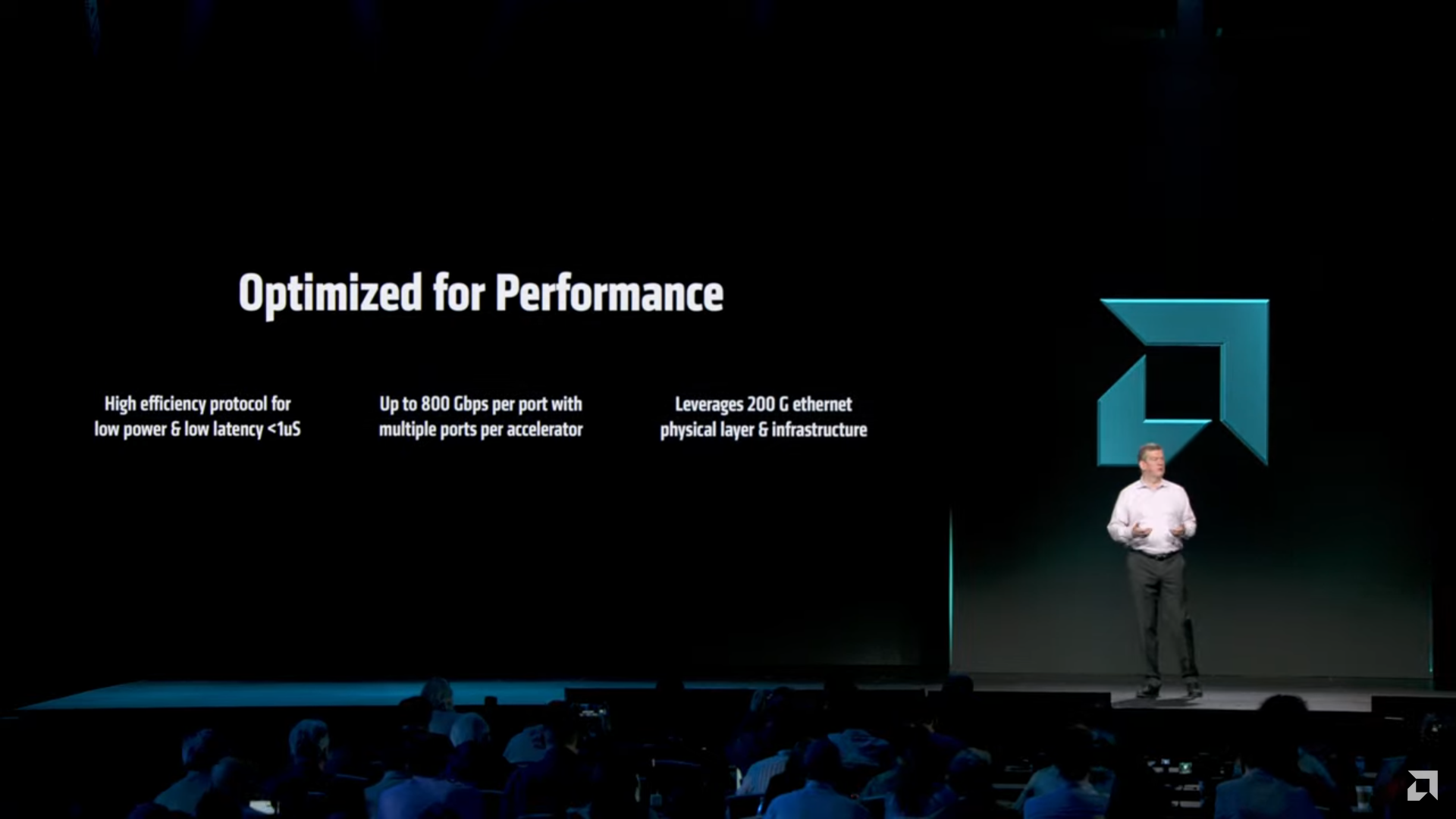
Optimized for Performance High efficiency protocol for low power & low latency <1uS Up to 800 Gbps per port with multiple ports per accelerator Leverages 200 G ethernet physical layer & infrastructure
-
 Bild
Bild
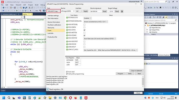
Software-Screenshot AVR Device Programming
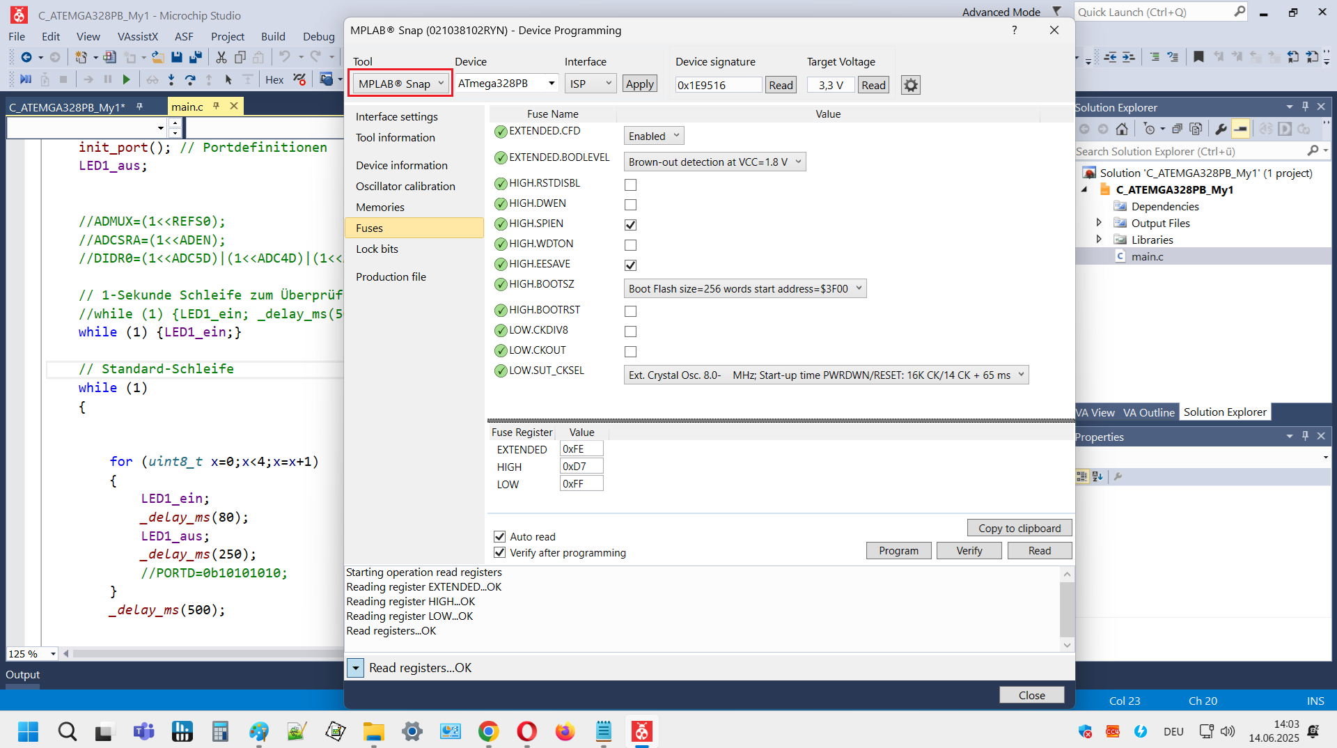
Voltage 3,3 V Interface settings EXTENDED.BODLEVEL Enabled Brown-out detection at VCC= 1.8 V Fuses HIGH.DWEN SPIEN LOW.CKOUT LOW.SUT.CKSEL Production file init_port(); // Portdefinitionen LED1_aus; ADMUX=(1<<REFS0); DIDR0=(1<<ADCSR0)|(1<<ADC D4); while (1) { LED1_ein; _delay_ms(500); } while (1) { LED1
-
 Bild
Bild
Software-Fenster zur AVR-Fuse-Programmierung
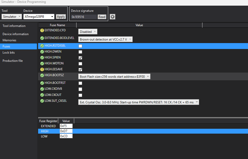
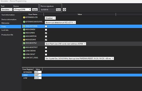
EXTENDED.CFD Disabled Device information EXTENDED.BODLEVEL Brown-out detection at VCC=2.7 V Memories HIGH.RSTDISBL Fuses HIGH.DWEN Lock bits HIGH.SPIEN Production file HIGH.WDTON HIGH.EESAVE HIGH.BOOTSZ Boot Flash size=256 words start address=$3F00 HIGH.BOOTRST LOW.CKDIV8 LOW.CKOUT LOW.SUT_CKSEL Ext. Crystal
-
Thread
ESP32 im PKW an Spannungsteiler Relais schalten
gibt es da etwas in (ich nenne es mal IC-Form), dass ich nur ein Bauteil habe? - Ist es zwingend LOW zu schalten oder wäre es egal ob Low oder High? (Dann natürlich mit umgedrehter Diode) Danke für eure Geduld - und nein, diese Konstellation habe ich noch nicht im Netz gefunden ;-) Viele Grüße
sind 0.8V und 2.5V. Mit dieser Eingangsschaltung ergibt das etwa unter ca. 4V wird garantiert als Low-Pegel erkannt, und ab ca. 9V wird als High-Pegel erkannt.
-
Thread
ATMega328PB lässt sich nur noch programmieren. Sonst keine Funktion mehr
steigt nichts. Ich verwende kein Bootloader. Folgende Fuses hab ich mittels avrdude programmiert: Low : 0xF7 High: 0xD9 Ext : 0xFD Der Controller läuft auf 3,3V mit einem Quarz von 7,3628MHz für 19,2 und 115,2k Baudraten. BOD ist auf 2,7V eingestellt. Wenn ich ein Pin auf HIGH setzte kann
Umschalten der IOs für die LEDs gehen, kann man mit einem Multimeter/Oszilloskop den Spannungspegel bei Low und High nachmessen, ob das plausibel ist und wie die Flanken sind, auch die Zeit mit Delay usw. auf Plausibilität prüfen; danach kann man mit der Software einen Schritt weitergehen, also ein Stückchen
-
Thread
NEMA17 Schrittmotor mit ESP32 und A4988 ansteuern
void setup() { pinMode(STEP_PIN, OUTPUT); pinMode(DIR_PIN, OUTPUT); digitalWrite(DIR_PIN, HIGH); // Set initial direction } void loop() { digitalWrite(STEP_PIN, HIGH); delayMicroseconds(800); digitalWrite(STEP_PIN, LOW); delayMicroseconds(800); } [/c] --- Doch leider macht
Sleep-Zustand zu versetzen. Besser wäre es, den Not-Reset Eingang über einen eigenen Pull-Up auf High zu legen.
-
Thread
Aufbau Bitmap Hex-file
contain 16 colors. Every byte in the image data represents two pixels. The byte is split into the higher 4 bits and the lower 4 bits and each value of them points to a palette entry. There are also standard colors for 16 colors mode (16 out of Windows 20 reserved colors (without the entries 8, 9, 246
must be saved as: A0 37 F2 8B 31 C4 00 00 to reach the multiple of four which is the next higher after six (eight). If you keep these few rules in mind while working with .bmp files it should be easy for you, to master it. */ [/c]
-
Thread
RISC/V-basierter Router von Shenzhen Xunlong, neue Renesas-MCU, große Politik und mehr
Namen im Bereich der stromsparenden MCUs besser zu etablieren: [c] The RA2L2 MCUs employ proprietary low-power technology that delivers 87.5 µA/MHz active mode and software standby current of just 250nA. They also offer an independent operating clock for the low-power UART, which can be used to wake up
ist. Es wird weiterhin usbtmc genutzt, allerdings ein neuer Übertragungsmodus mit zusätzlichen low-level GPIB Funktionen die vom gpib Treiber benötigt werden. Hab gestern die upgedatete Firmware abgeliefert.
-
Thread
ALL-ESP8266-IoT-Relais
#14 Relais an #12 Relais aus #0 Taster ?? die LED Ich find keine Info, ob die Relais mit LOW oder mit HIGH anziehen ob mi #14, #12 auch GPIO14, GPIO12 gemeint ist ob die LED on board, die mit Drücken der Taste #0 immer mitleuchtet, auch über ein GPIO anzusteuern ist .. so ein Schlatplan
bereits in /dev/null 2. ist mit #12,#14 GPIO gemeint = geht also einfach ein digitalWrite(12, HIGH oder LOW); digitalWrite(14, HIGH oder LOW); Ist der Impulse von LOW - HIGH (delay) LOW oder HIGH - LOW (delay) HIGH zu schalten ? 3. ist die LED schaltbar - wenn ja, welche GPIO ?
-
 Bild
Bild
Datenblatt Ausschnitt Dual Common Cathode Schottky Rectifier
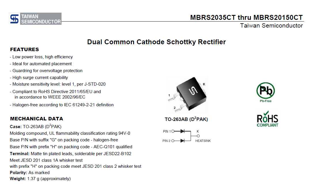
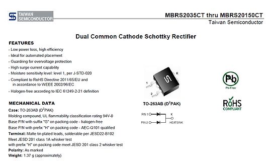
TAIWAN SEMICONDUCTOR MBRS2035CT thru MBRS20150CT Dual Common Cathode Schottky Rectifier FEATURES - Low power loss, high efficiency - Ideal for automated placement - Guardring for overvoltage protection - High surge current capability - Moisture sensitivity level: level 1, per J-STD-020 - Compliant to
-
Thread
BBC 198 kHz Abschaltung
vergleichbar was auch im KFZ Bereich Realität war - Deutschland, die Niederlande usw. konnten zwar High Tech RX und Autos aber halt fast nur für den zahlungskräftigen Export und ganz wenige Kunden "zu Hause") aber spätestens für die Röhrenradios nach den 2WK findet man auch recht viel von kompetenten
interference from other signals in the LW band, and allows the Droitwich signal to reach the same area with lower energy costs." ACK! Auf jeden Fall ist schon jetzt die 198 kHz deutlich schwächer als Polen auf 225 kHz.
-
 Bild
Bild
Abfotografiertes Oszilloskop mit Sinuswelle
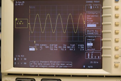
DEviation of the data values From the mean value over an integral number OF periods 133I sweeps: average low high sigma Freq(1) 500.011 MHz 494.590 504.811 1.160 csdev(1) 758.4mV 752.5 764.3 2.0 25 GS/s AUTO CH1 CH2 EXT
-
 Bild
Bild
Handgezeichneter Schaltplan mit MCU und Logik
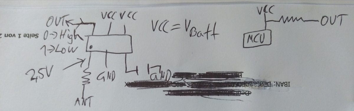
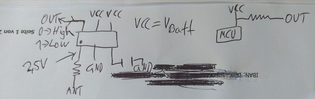
OUT VCC VCC VCC = V_Batt MCU OUT 0 -> High 1 -> Low GND ANT 2.5V GND
-
Thread
ADA lernen JA/NEIN? Einstieg in Embedded Systems.
heute genauso selten wie Tippsen. Und lass Dich nicht täuschen: Entwürfe in UML oder anderen "High-Level"-Sprachen sind oft eher vage Ideen unverstandener Genies.
Kreise gibt's wohl einige, die damit modellieren, aber fuers Engineering ist man wieder bei einer Low-Level-Transfersprache wie Verilog. VHDL wird von einigen FPGA-Herstellern fortschreitend stiefmuetterlicher unterstuetzt.