Unidirectional* PLASTIC SURFACE MOUNT The SMB series is designed to protect voltage sensitive components from high voltage, high energy transients. They have ZENER OVERVOLTAGE excellent clamping capability, high surge capability, low zener TRANSIENT SUPPRESSORS impedance and fast response time. The SMB series is
Unidirectional* http://onsemi.com The SMC series is designed to protect voltage sensitive components from high voltage, high energy transients. They have PLASTIC SURFACE MOUNT excellent clamping capability, high surge capability, low zener ZENER OVERVOLTAGE impedance and fast response time. The SMC series is
"billig" CR-2032 und CR-2025 für diverse Geräte gekauft, die nach kurzer Zeit (1-2 Monate) wieder "Low Bat" gezeigt haben. Seit ich "Markenzellen" (in dem Fall Varta schnell bei Edeka um die Ecke) gekauft habe halten die Zellen länger als ein Jahr.
Patent No. 20 2019 106 212 Japan Patent No. 3223244 USA Patent No. 10,788, 519 Features: 1. Super high resolution: DC 1mA, AC 0.1mA. 2. DCA max. 200.0A. 3. 23mm jaw diameter. 4. One touch zero for DCA adjustment. 5. Auto-power-off (15 min.) and Backlight. 6. AC current/voltage measurement: True RMS.
https://elektro.turanis.de/html/prj237/index.html SIM800L: DTR (De-)Aktiviert den Sleep-Modus. HIGH: Modul geht in Sleep-Modus (serielle Kommunikation wird unterbrochen) LOW: Modul wacht wieder auf. Den Pin läßt Du von einem ATtiny13 oder Padauk bedienen indem Du alle 10min für 1min das Modul
verschluckt, weil er das Startbit des nächsten Bytes garnicht mitbekommen hat. Der sieht dann das erste High/Low im Payload als Begin eines Startbits. Je nach Inhalt der Kommunikation kann es sogar passieren, dass er die Wordsynchronisation ab dann dauerhaft verliert. Bis dann irgendwann mal eine hinreichend
daß andere UART Implementationen es so machen. Das ATmega8 Datenblatt sagt aber eindeutig: "A new high to low transition indicating the start bit of a new frame can come right after the last of the bits used for majority voting. For Normal Speed mode, the first low level sample can be at point marked
900mA?) da ist, aber ein zweiter USB2, dann ein Y-Kabel verwenden. Helfen könnten auch ein 10000µF low ESR Stützelko, ansonsten aktiven Hub mit eigenem Netzteil zwischenschalten.
Wolf17 schrieb im Beitrag #7896316: > Helfen könnten auch ein 10000µF low ESR Stützelko, Niemals so dick direkt an USB!
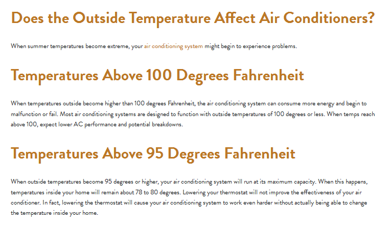
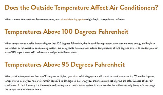
experience problems.
Temperatures Above 100 Degrees Fahrenheit
When temperatures outside become higher than 100 degrees Fahrenheit, the air conditioning system can consume more energy and begin to malfunction or fail. Most air conditioning systems are designed to function with outside temperatures of 100 degrees or less. When temps reach above 100, expect lower AC performance and potential breakdowns.
Temperatures Above 95 Degrees Fahrenheit
When outside temperatures become 95 degrees or higher, your air conditioning system will run at its maximum capacity
disable Isb2 Standby current (CMOS) 1uA 5uA Vcc=Vcc max, CE#=vcc +0.3V, other pin disable Vil Input Low Voltage -0.3V 0.8V Vih Input High Voltage 0.7xVcc Vcc+0.3V Vhv Very High Voltage for Auto Select 11.5V 12V 12.5V Vol Output Low Voltage 0.45V Iol=2.1mA, Vcc=Vcc min Voh1 Ouput High Voltage (TTL) 2.4V
4N32/4N33 High Isolation Photo Coupler Features Description High isolation 5000 VRMS The 4N32, 4N33 series combine an AlGaAs DC input with transistor output infrared emitting diode as the emitter which is Operating
wusste das > nicht, und der hat's einfach gemacht. 😂 Die Pins müssen 3 Zustände annehmen können, Low, High und Hochohmig Damit die Helligkeit nicht schwankt ist es am einfachsten immer nur 2 Pins aktiv (stromführend) zu haben, einen Low einen High und den Rest hochohmig und immer alle Kombinationen
Lutz schrieb im Beitrag #7887409: > Die Pins müssen 3 Zustände annehmen können, Low, High und Hochohmig Ach so. Das ist für heutige Mikrocontroller doch nichts besonderes.
das Fahrzeug gleich gegenüber der Ladesäule > authentifizieren kann. PWM ist tatsächlich nur zur Low-Level-Kommunikation von Status und max. Strom gedacht. Vermutlich, weil die Umsetzung Fahrzeugseitig über Schalter und Widerstand robust und leicht zu implementieren ist. Es gibt sogar ein High-Level-Protokoll
instruction overhead void send_bit(uint8_t bit) { if (bit) { PORTA.OUTSET = TX_PIN; // High (Transmitter ON) } else { PORTA.OUTCLR = TX_PIN; // Low (Transmitter OFF) } _delay_us(BIT_DURATION_US); } void send_byte(uint8_t data) { // Start bit (active low, so
// Read DT_PIN to determine direction if (PORTA.IN & DT_PIN) { // DT_PIN is HIGH when CLK_PIN goes HIGH -> Counter-clockwise (Left) enqueue_task(ENCODER_LEFT); } else { // DT_PIN is LOW when CLK_PIN goes HIGH -> Clockwise (Right) enqueue_task
Analog Devices ADL8103 - robuster LNA. LNAs stehen oft ganz am Anfang der Signalkette. Aus dem Namen Low Noise Amplifier lässt sich allerdings schon ableiten, dass passive Komponenten zum Eingangsschutz der Performance des Systems nicht unbedingt zuträglich sind. Mit dem ADL8103 lanciert Analog Devices
bis zu 500 Stunden Besprühung mit Salzwasser aushalten soll. ### TE Connectivity Mini CT Low-Profile Inverted - Steckverbinder für die Rückseite Normalerweise gilt, dass ein Steckverbinder auf der Seite Verbindungen entgegennimmt, auf der er festgelötet ist. TE Connectivity dreht dieses Konzept
INPUT_PULLUP); pinMode(CADENCE_PIN, INPUT_PULLUP); pinMode(BRAKE_PIN, OUTPUT); digitalWrite(BRAKE_PIN, LOW); // brake - motor not active digitalWrite(LED_PIN, HIGH); // LED on: Motor on / Brake not active // Pin Change Interrupt für ausgewählten Pin aktivieren PCICR |= (1 << PCICR_BIT); PCMSK_REG |= (1 <
Package Packing IL8190N DIP-16 Tube IL8190DW T = -40 to 105 C SOP-20 Tube Direct Sensor Input A High Output Torque IL8190DWT SOP-20 T & R Low Pointer Flutter High Input Impedance Overvoltage Protection Return to Zero PIN ASSIGNMENT DIP-16 SOP-20 December, 2012, Rev. 02 IL8190 ABSOLUTE MAXIMUM
will soll der GPIO0 doch als Output LOW den Transistor ausschalten. Der Reset (Active Low) vom Watchdog wird dann nicht an den ESP32 durchgeschaltet (falls einer auslöst) Im Normalbetrieb ist der GPIO0 HIGH und der Transistor sollte mit
funktionieren sollte. Zur Funktionsweise: Normalerweise wird GPIO0 (durch einen 12kΩ Pull-up) auf HIGH gezogen. Wenn dann der Watchdog-Ausgang auf LOW geht, schaltet Q1 ein und zieht den EN Eingang des ESP auch auf LOW. Die Annahme war, das GPIO0 beim Programmieren die ganze Zeit auf LOW liegt (stimmt
value [7:5] Reserved RO Reserved 0 PWM5 output polarity control: 4 RB_PWM5_POLAR RW 1: Default at high level, active low; 0 0: Default at low level, active high. PWM4 output polarity control: 3 RB_PWM4_POLAR RW 1: Default at high level, active low; 0 0: Default at low level, active high. PWM3 output polarity control: 2 RB_PWM3_POLAR RW 1: Default at high level, active low; 0 0: Default at low level, active high. PWM2 output polarity control: 1 RB_PWM2_POLAR RW 1: Default at high level, active low; 0 0: Default at low level, active high. PWM1 output
Danke für die vielen Rückmeldungen. Ich benötige nur ein analoges Signal um im Arduino einen Pin mit HIGH und LOW anzusteuern. Mir geht es darum wenn ein beliebiger Ton am PC erscheint soll am Arduino analogen Pin ein HIGH Signal ankommen. Bei Ton aus das Signal LOW.
einfach das Signal verstärken, gleichrichten und damit ein Schmitt-Trigger ansteuern, fertig ist das High-Low-Signal. Man kann mit diesen High-Low-Signal dann auch noch ein Arduino ansteuern, wenn man will.
smart home products, supporting Bluetooth, Zigbee, and Thread with support for Matter. Built with high Flash and RAM overhead of 4 MB and 512 kB, respectively, the SiXG301 helps future-proof customer designs as the requirements for Matter and other more demanding IoT applications continue to grow. This
veröffentlicht worden - die folgende Liste gibt drei hervor. Exploring Simple Siamese Network for High-Resolution Video Quality Assessment => https://research.samsung.com/blog/Exploring-Simple-Siamese-Network-for-High-Resolution-Video-Quality-Assessment „Gaze detection“ zur Hervorhebung relevanter
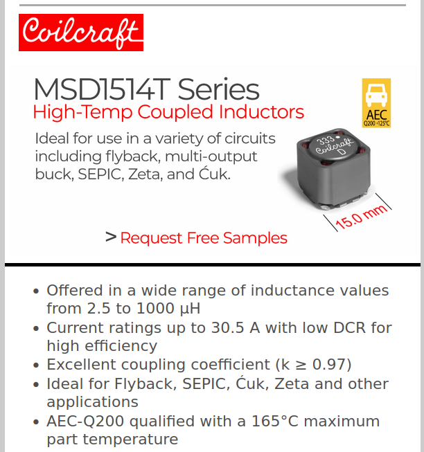
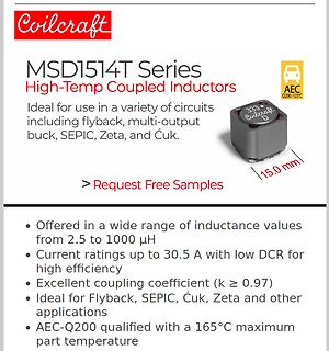
Coilcraft MSD1514T Series High-Temp Coupled Inductors. Ideal for use in a variety of circuits including flyback, multi-output buck, SEPIC, Zeta, and Ćuk. > Request Free Samples. Offered in a wide range of inductance values from 2.5 to 1000 µH. Current ratings up to 30.5 A with low DCR for high efficiency. Excellent coupling coefficient (k >= 0.97). Ideal for Flyback, SEPIC, Ćuk, Zeta and other applications. AEC-Q200 qualified with a 165°C maximum part temperature.
: Target frequency 25 kHz, acceptable operational range 21 kHz to 28 kHz Maximum voltage for logic low: VIL = 0.8 V Absolute maximum current sourced: Imax = 5 mA (short circuit current) Absolute maximum voltage level: VMax = 5.25 V (open circuit voltage) This signal must be pulled up to a maximum of
welchen Punkten hast Du also gemessen, und wie sieht die Anbindung > der Tastköpfe aus? Die Uds am High Side habe ich direkt am Mosfet mit einem High voltage differential probe 100Mhz gemessen (Micsic DP701)
wenig ab, das meiste kriegt der Treiber auf den Arsch gebrannt, der das Gate nämlich sehr gerne auf LOW halten würde.
BSB = %00000, RW=1(write), OM =%00 /* FUNCTION ************************************/ void W5500_CS_low (void) { // your code for I/O port P1OUT &= ~BIT1; } /* --- W5500_CS_low --- */ /* FUNCTION ************************************/ void W5500_CS_high (void) { // your code for I/O port P1OUT |= BIT1;
Tube ■ Non-linear soft-start for monotonic output voltage rise Applications ■ 600 V-rail compatible high-side gate driver with ■ LCD and PDP TV integrated bootstrap diode and high dV/dt ■ Desktop PC, entry-level server immunity ■ Telecom SMPS ■ -300/800 mA high-side and low-side gate ■ AC-DC adapter, open
vanished (that is until the the oscillator capacitor to VoscL. At that moment, the signal “DT” is high − “DT” is generated by the current sense block so that it is high during the dead−time and low comparator turns low and initiates a new charge phase. If the circuit is to be externally triggered, the
: Target frequency 25 kHz, acceptable operational range 21 kHz to 28 kHz Maximum voltage for logic low: VIL = 0.8 V Absolute maximum current sourced: Imax = 5 mA (short circuit current) Absolute maximum voltage level: VMax = 5.25 V (open circuit voltage) § 9 Electrical Specifications 10 Fan Speed Control
otherwise noted. TPS2112A, TPS2113A PARAMETER TEST CONDITIONS MIN TYP MAX UNIT LOGIC INPUTS (EN) High-level input voltage VIH 2 V Low-level input voltage VIL 0.7 V Input current EN = High, sink current 1 μA EN = Low, source current 0.5 1.4 5 SUPPLY AND LEAKAGE CURRENTS VI(VSNS)= 1.5 V, EN = Low (IN1
input will power the output. • If both inputs are not valid, then the output is Hi-Z. • ST is pulled high when the output is Hi-Z or IN1. It is pulled low when IN2 is powering the output. • If CP2 is pulled low, then the TPS2121 ignores this pin. • When CP2 is pulled high, this enables fast switchover and
IN1) I(IN2) ILIM TPS2114A PARAMETER TEST CONDITIONS MIN TYP MAX UNIT LOGIC INPUTS (D0 AND D1) VIH High-level input voltage 2 V V Low-level input voltage 0.7 V IL D0 or D1 = high, sink current 1 µA Input current at D0 or D1 D0 or D1 = low, source current 0.5 1.4 5 μA SUPPLY AND LEAKAGE CURRENTS D1 = high
solid, gas) : Combustible Solids Upper explosion limit / Upper : No data available flammability limit Lower explosion limit / Lower : No data available flammability limit Vapour pressure : < 0.001 hPa (20 °C) Relative vapour density : No data available Relative density : 0.87 (20 °C) Reference substance:
PT100 Schaltung) Maxim AN3450 Positive Analog Feedback Compensates PT100 Transducer Maxim AN4875 High-Accuracy Temperature Measurements Call for Platinum Resistance Temperature Detectors (PRTDs) and Precision Delta-Sigma ADCs Microchip AN1154 Precision RTD Instrumentation for Temperature Sensing Analog
To 0.1 Degree AN131 (PDF momentan nicht verfügbar) --> Digitale Temperatursensoren. AM2301 / DHT21. Low Cost One-Wire Sensoren Relativ großer Sensor Stromversorgung: DC 3.3 - 5.2 V Ausgangssignal: 1-Draht-Bus - digitales Signal (One wire) Sensorelement: Polymer Feuchtigkeits-Kondensator Messbereich: Luftfeuchtigkeit
dann folgendes: [c] The mid-coat uses advanced aerogel insulation materials, which have extremely low thermal conductivity, helping to effectively block the transmission and penetration of heat. The topcoat is an upgraded version of heat-reflective coatings, offering higher reflectivity to further reduce solar heat absorption. It also has high thermal emittance, allowing it to directly emit heat back into the atmosphere, mitigating urban heat island effects. Both of these coatings are low-VOC and fully water-based. Adds Yin: “The science
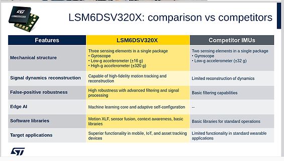
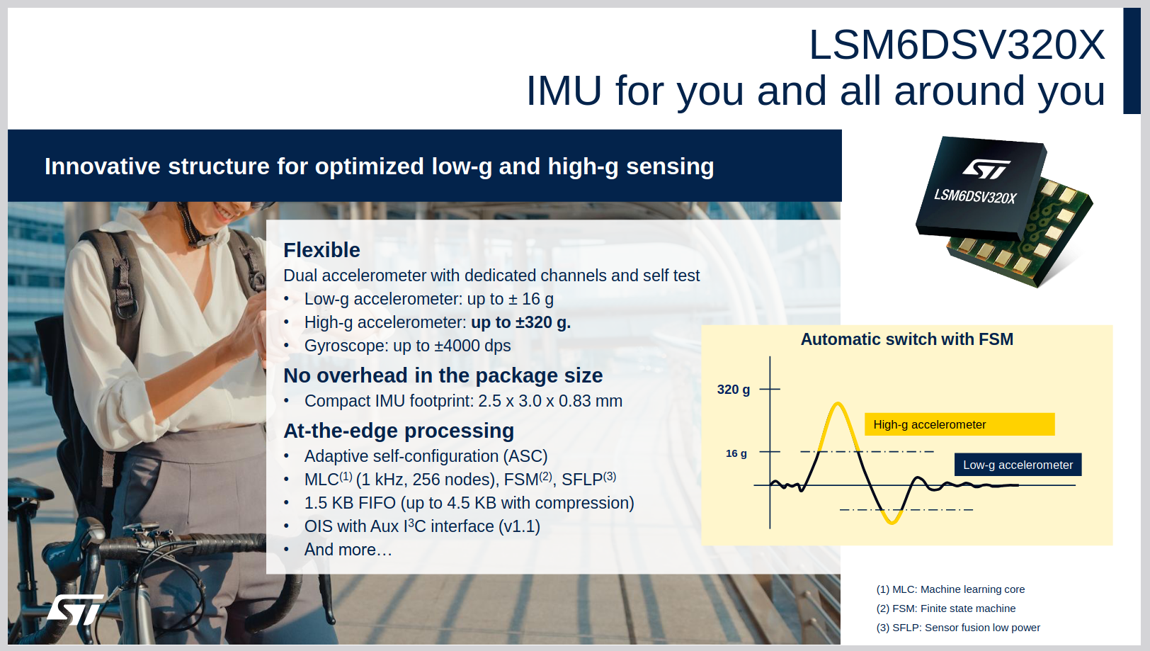
LSM6DSV320X
IMU for you and all around you
Innovative structure for optimized low-g and high-g sensing
Flexible
Dual accelerometer with dedicated channels and self test
Low-g accelerometer: up to ± 16 g.
High-g accelerometer: up to ±320 g.
Gyroscope: up to ±4000 dps
No overhead in
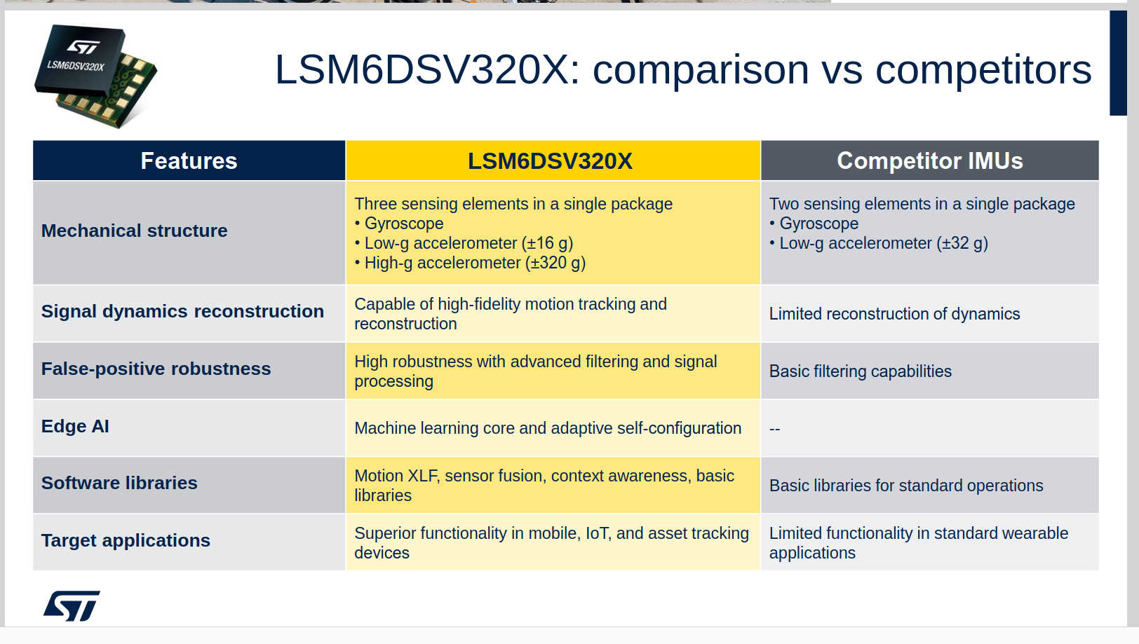
LSM6DSV320X
Competitor IMUs
Mechanical structure
Three sensing elements in a single package
• Gyroscope
• Low-g accelerometer (±16 g)
• High-g accelerometer (±320 g)
Two sensing elements in a single package
• Gyroscope
• Low-g accelerometer (±32 g)
Signal dynamics reconstruction
Capable of high-fidelity motion tracking and reconstruction
Limited reconstruction of dynamics
False-positive robustness
High robustness with advanced filtering and signal processing
Basic filtering capabilities
Edge AI
Machine learning core and adaptive self-configuration
--
Software libraries
Motion XLF, sensor fusion, context

 Bild
Bild
 Bild
Bild
 Bild
Bild
 Bild
Bild
 Bild
Bild
 Bild
Bild

 Bild
Bild