-
PDF
Handy-Netzteile-Vergleich.pdf
5V 800mA p 0 S , SPS-800 Mini o 0 Samsung 4,75V 550mA V ATADS30EBC A 0 0 Sony Ericsson 5V 550mA 0 EP300 Huawei 5V 1A 0 HW-050100E1W 6 0 Phihong (Acer) 5,35V 2A PSAI10R-050Q 4 , 0 2 , 0 0 ,0 10 100 200 300 400 500 600 700 800 900 1000 1100 1200 1300 1400 1500 1600 1700 1800 1900 2000 2100 2200 0 mA Seite 1
in „Messreihe 5V USB Netzteile“ · Mikrocontroller und Digitale Elektronik ·
-
PDF
IRL1004_IR.pdf
D ––– ––– 130 (Body Diode) A showing the ISM Pulsed Source Current integral reverse G ––– ––– 520 (Body Diode) p-n junction diode. S V SD Diode Forward Voltage ––– ––– 1.3 V TJ= 25°C, S = 78A, GS = 0V trr Reverse Recovery Time –
in „Schon wieder: Verpolungsschutz-MOSFET und LogicLevel-FET gesucht“ · Analoge Elektronik und Schaltungstechnik ·
-
PDF
SIOV_Calculation_2.pdf
100 kHz. See VR the effect of HF alternating current on the varistor type 2381 595 52516; C = 480 pF drawing. 600 V1 103 400 V (V) VO 200 50 Hz 100 Hz 1 kHz 10 kHz 102 00 2 4 6 8 10 I (A) Influence on varistor when V i1 1000 V (R = 250 Ω) 100 kHz 10 -2 -1 EQUIVALENT CIRCUIT MODEL 10 10 1 I (mA) 10
in „Varistor dimensionieren“ · Mikrocontroller und Digitale Elektronik ·
-
Datei
Timer0.asm
gpio ;Alle LEDs an movwf gpio_copy ;Kopie vom GPIO Port btfsc gpio,5 ;Schnell o. Langsam ? goto PWM_A ;Kurze Schleife goto PWM_B ;Lange Schleife PWM_A: incf pwm,1 ;PWM um 1 erhöhen btfss pwm,3 ;Schleife: 8x durchläufe? goto LED0 ;NEIN, LEDs und Timer0 überprüfen clrf pwm ; goto up_down0 ;JA, RGB-Reg
in „PIC 16F872 Initialisierung. Wie gehts richtig?“ · Mikrocontroller und Digitale Elektronik ·
-
PDF
211-1-PLEXIGLAS-GS-XT-de.pdf
Baustoffklasse DIN 4102 B2 B2 B2 - BS 476, Teil 7 + 6 Class 3 Class 3 - - BS 2782 TP (b) TP (b) - - Methode 508 A E E E - DIN EN 13501 Allgemeines Bauaufsichtliches P-K017 / 11.06 P-K018 / 02.07 P-K019 / 05.07 - - Prüfzeugnis ISO 306, Vicat-Erweichungstemperatur 115 103 102; 100; 100; 97 °C Methode B 50 Formbeständigkeit
in „Luftspalt in den Ferritkern einbringen, welche Folie, Material“ · Analoge Elektronik und Schaltungstechnik ·
-
PDF
74HC164_STM.pdf
SWITCHINGCHARACTERISTICS TEST. 7/12 M54/M74HC164 Plastic DIP14 MECHANICAL DATA mm inch DIM. MIN. TYP. MAX. MIN. TYP. MAX. a1 0.51 0.020 B 1.39 1.65 0.055 0.065 b 0.5 0.020 b1 0.25 0.010 D 20 0.787 E 8.5 0.335 e 2.54 0.100 e3 15.24 0.600 F 7.1 0.280 I 5.1 0.201 L 3.3 0.130 Z 1.27 2.54 0.050 0.100 P001A 8/12 M54/M74HC164 Ceramic DIP14/1 MECHANICAL DATA mm inch DIM. MIN. TYP. MAX. MIN. TYP. MAX. A 20 0.787 B 7.0 0.276 D 3.3 0.130 E 0.38 0.015 e3 15.24 0.600 F 2.29 2.79 0.090 0.110 G 0.4 0.55 0.016 0.022 H 1.17 1.52 0.046 0.060 L 0.22 0.31 0.009 0.012 M 1.52 2.54 0.060 0.100 N 10.3 0.406 P 7.8
in „11110000 im Schieberegister rotieren lassen“ · Mikrocontroller und Digitale Elektronik ·
-
PDF
1809271221_Texas-Instruments-DAC5571IDBVR_C24061.pdf
SCL Clock Standard mode 4.0 µs Fast mode 600 ns High-speed mode, CB- 100 pF max 60 ns High-speed mode, CB- 400 pF max 120 ns t ; t Setup Time for a Repeated Standard mode 4.7 µs SU STA START Condition Fast mode 600 ns High-speed mode 160 ns tSU
in „Hilfe bei der Berechnung (Voltage Divider)“ · Analoge Elektronik und Schaltungstechnik ·
-
PDF
IRL1004.pdf
D ––– ––– 130 (Body Diode) A showing the ISM Pulsed Source Current integral reverse G ––– ––– 520 (Body Diode) p-n junction diode. S V SD Diode Forward Voltage ––– ––– 1.3 V TJ= 25°C, S = 78A, GS = 0V trr Reverse Recovery Time –
in „Mosfet als Schalter 100W“ · Analoge Elektronik und Schaltungstechnik ·
-
Datei
Digitales_Wattmeter_mit_AD8307__PIC16F876__LCD-Anzeige____C.html
</font></font></a><font style="vertical-align: inherit;"><font style="vertical-align: inherit;"> Leiterplattengröße ist 79 mm breit und 37 mm hoch</font></font></p><p> <a href="https://www.webx.dk/oz2cpu/radios/milli-curves.htm
in „AD8307. Wie die Leistung kalibrieren?“ · HF, Funk und Felder ·
-
PDF
G065VN01-V2.pdf
G065VN01 V2 2.2 Optical Characteristics The optical characteristics are measured under stable conditions a(Room Temperature). Item Unit Conditions Min. Typ. Max. Remark White Luminance cd/m2 FPWM = 100% 600 800 - Note 1 (center point) Uniformity 5 Points Note % - 1.25 1, 2, 3 Contrast Ratio 400 600 - Note
in „Tektronix TDS 510A CRT Video Display Unit defekt“ · Analoge Elektronik und Schaltungstechnik ·
-
PDF
surrpressordiode.pdf
l Half Value -PP k P IPPM 2 a k P 1 e 50 10/1000 µsec Waveform M - as defined by R.E.A. P 0.2 x 0.2" (0.5 x 0.5 mm) M P Copper Pad Areas P I td 0.1 0 0.1 µs 1.0 µs 10 µs 100 µs 1.0 ms 10 ms 0 1.0 2.0 3.0 4.0 td - Pulse Width
in „DC Geräteeingang“ · Analoge Elektronik und Schaltungstechnik ·
-
PDF
ILX535K.pdf
B-U OV GTUOV 3 a o 5 2 1 l p T p n 0 A a 1 r 1 DNG R-TUOV 2 T 2 k . 5 2 D NG SRφ 1 0 T 2 1 O V S φ 1 z I H 6 1 / = µ S i 4 f c e i a C a n a i 2 D t 1 ∗ c µ l . p 0 A – 7 – ILX535K Example of Representative Characteristics
in „Linearen CCD auslesen“ · Mikrocontroller und Digitale Elektronik ·
-
PDF
SGMOP17C.pdf
≤ +125℃ 2.9 A POWER SUPPLY (1) V S 4.5V to 36V 117 145 Power Supply Rejection Ratio (PSRR) dB -40℃ ≤ T A +125℃ 115 V O 2.5V 450 600 Quiescent Current (Q ) μA -40℃ ≤ T A +125℃ 790 DYNAMIC PERFORMANCE Gain-Bandwidth
in „Identifikation SOT23-5 ST3SK“ · Analoge Elektronik und Schaltungstechnik ·
-
PDF
inverses_Pendel.pdf
in die Gleichung (2.1) folgt: m P⋅lSP m P ⋅g l SP c r ϕ( t = − J ⋅(m + m )⋅(FM − μr⋅ W (t) ⋅cos(ϕ(t))+ J ⋅sin(ϕ(t))− J ϕ(t) (2.3) A W P A A Die Linearisierung der Differenzialgleichungen erfolgt im Arbeitspunkt. Im Arbeitspunkt befindet
in „Regler für Strecke 1/(T^2*s^2-1)“ · Digitale Signalverarbeitung / DSP / Machine Learning ·
-
PDF
AN-3004.pdf
forward blocking voltage between the two Basic Driving Circuit main terminals (MT1 and MT2) which is a minimum of 600 Assuming the circuit shown in Figure 7 is in the blocking or volts for all MOC3061 family members.Also, voltage ramps "off" state (which means IFis zero), the full ac line voltage (transients
in „MOC3063 vs MOC3063M“ · Analoge Elektronik und Schaltungstechnik ·
-
 Bild
E-Scooter Akku mit Ladegerät und Shop-Angebot
36V 10Ah 10S3P Roller Ersatzzakku 15A BMS für 250W 600W E-fahrrad Scooter €99,99 (28) 36V 10Ah 600watt 10S3P Li Ion Akku 15A BMS passend für m365 Pro Elektrofahrrad Scooter XT60 / T Stecker Intelligente... 15 Die Leute
in „Gute Quellen fuer Akkupack Pedelec gesucht!“ · Fahrzeugelektronik · · Screenshots

-
PDF
lt1157.pdf
condition. Note 2:Quiescent current ON is per driver and is measured independently. 2 LTC1157 W U T P CA L PER F O R A E C CHARACTERIST ICS Standby Supply Current Supply Current per Driver ON Gate Voltage Above Supply 12 600 12 V = V = 0V ONE INPUT = ON ) TIN= 25°C2 OTHER INPUT = OFF ( 10 A 500 G 10
in „3V Gate-Treiber gesucht“ · Analoge Elektronik und Schaltungstechnik ·
-
PDF
________________KENT-128x32_ILV.pdf
Function: LookupParams // Purpose: Updates the display with the image data in the driver. // Inputs: pNumScans – ptr. to number of image scans // pNumPulses – ptr. to number of drive pulses per scan on a row // pDriveTicks – ptr. to number of ticks in a drive pulse // pPauseTicks – ptr. to number of ticks
in „Low Power Grafik Display“ · Mikrocontroller und Digitale Elektronik ·
-
PDF
HCPL-063.pdf
Overvoltage, ini= 10 sec) Safety Limiting Values (Maximum values allowed in the event of a failure, also see Figure 16, Thermal Derating curve.) Case Temperature T 175 150 ˚C S Input Current IS,INPUT 230 150 mA Output Power P S,OUTPUT 600 600 mW Insulation Resistance at TS, IO= 500 V R S ≥
in „Logic Gate Optocoupler“ · Mikrocontroller und Digitale Elektronik ·
-
PDF
21709c_EEPROM.pdf
A BYTE ADDRESS (n) A BYTE T R R DATA (n) O T T P S S P SDA LINE A A A N C C C O BUS ACTIVITY K K K A C K FIGURE 7-3: SEQUENTIAL READ BUS ACTIVITY CONTROL S MASTER BYTE T DATA (n) DATA (n + 1) DATA (n + 2) DATA (n + X) P SDA LINE P A A A A N BUS ACTIVITY C C C C O K K K K A C K DS21709C-page 10 2003 Microchip Technology Inc. 24AA02/24LC02B 8.0 PIN DESCRIPTIONS The descriptions of the pins are listed in Table 8-1. TABLE
in „EEPROM mit Infineon XC2200 ueber IIC benutzten“ · Mikrocontroller und Digitale Elektronik ·
-
PDF
21709c.pdf
A BYTE ADDRESS (n) A BYTE T R R DATA (n) O T T P S S P SDA LINE A A A N C C C O BUS ACTIVITY K K K A C K FIGURE 7-3: SEQUENTIAL READ BUS ACTIVITY CONTROL S MASTER BYTE T DATA (n) DATA (n + 1) DATA (n + 2) DATA (n + X) P SDA LINE P A A A A N BUS ACTIVITY C C C C O K K K K A C K DS21709C-page 10 2003 Microchip Technology Inc. 24AA02/24LC02B 8.0 PIN DESCRIPTIONS The descriptions of the pins are listed in Table 8-1. TABLE
in „24LC02B mit (scheinbar) seltsamer Adressierung“ · Mikrocontroller und Digitale Elektronik ·
-
PDF
CPC1981Y.pdf
(V) P TypicalTurn-OnTime TypicalTurn-OffTime Typical LED ForwardVoltage Drop vs.LED Forward Current vs. LED Forward Current vs.Temperature (IL=100mA ) DC (IL=100mA ) DC )1.8 5.0 0.09 ( 4.5 p1.7 0.08 r1.6 s
in „Welches SSR für Zündunterbrecher bzw. Alternativen zum SSR?“ · Analoge Elektronik und Schaltungstechnik ·
-
Datei
EDID_HDMI.txt
000000FD 00324B1E 5012000A 20202020 20200138 02032EF2 4D010384 05071012 9314161F 20222609 07071117 50830100 0070030C 001000B8 2D20A006 01410000 00008C0A D08A20E0 2D10103E 9600C48E 21000018 023A8018 71382D40 582C4500 C48E2100 009E011D
in „Display-Set LS-7“ · Mikrocontroller und Digitale Elektronik ·
-
PDF
STK5Q4U362J-E-D.PDF
claimed as the property of others. STK5Q4U362J-E Advance Information Intelligent Power Module (IPM) 600 V, 10 A The STK5Q4U362J-E is a fully-integrated inverter power stage consisting of a high-voltage driver, six IGBT’s and a thermistor, suitable www.onsemi.com for driving permanent magnet synchronous
in „Ersatz für ON-Semi STK5Q4U362J-E / STK5Q4U363J-E bzw. passt da NFAQ1060L33T / NFAQ1060L36T“ · Analoge Elektronik und Schaltungstechnik ·
-
PDF
samsung_242mp_chassis_po24fs.pdf
,1A,-,TP 1 SA IC3004 1203-002351 IC-POSI.FIXEDREG. LF25C,DPAK,3P,240MIL,PLASTIC,2.45V/2.55V,-,-40TO+125C,-,2.85V/16V,TP 1 SA IC600 1203-003059 IC-SWITCHVOL.REG. MP1583,SOIC,8P,4.9x3.9mm,PLASTIC,1.22/21V,
in „Defekt an Samsung 242MP TV/Monitor“ · Mikrocontroller und Digitale Elektronik ·
-
Datei
main.c
//***************************************************************************** // MSP-FET430P140 Demo - DMA0, Rpt'd Blk to DAC0, Sine Output, TACCR1, DCO // // Description: DMA0 is used to transfer a sine look-up table word-by-word // as a repeating block to DAC12_0. The effect is sine wave output
in „Bitte, bitte helft mir: MSP430 DMA Problem“ · Mikrocontroller und Digitale Elektronik ·
-
PDF
SCM1.pdf
2600 DC-400 5.5 .15 — 7.0 31 (typ.) 25 (min.) 15 (typ.) 12 (min.) –– CB539 jx 5.95 ALY-4 3300-4300 DC-600 5.7 .15 — 8.0 28 (typ.) 23 (min.) 15 (typ.) 12 (min.) –– CB539 jx 5.95 ASK-1-KK81 1-600 DC-600 5.58 .06 7.0 8.5 50 30 35 25 30 20 45 35 30 20 25 15 1-76 KK81 w 6.95 = ASK-2-KK81 1-1000 DC-1000 6.79
in „[V] SL11H, USS720E ua.“ · Markt ·
-
PDF
Geigerz__hlerArtikel.pdf
mit 80035 18 T1: Bild 1a. Prinzipieller Aufbau eines Geiger- Solange die Hochspannung unter dem Müller-Zählrohrs. Es besteht aus einen mit mit P1 eingestellten Sollwert liegt, ist Edelgasgemisch (meist Halogen) gefüllten T1
in „Geiger Counter Sparkfun“ · Mikrocontroller und Digitale Elektronik ·
-
PDF
PHC2300_3_1_.pdf
charge N-channel VGS = 10 V; DS= 50 V; D = 170 mA − 226 − pC P-channel V = −10 V; V = −50 V; I = −115 mA − 68 − pC GS DS D QGD gate-drain charge N-channel VGS = 10 V; DS= 50 V; D = 170 mA − 1385 − pC P-channel V = −10 V; V = −50 V; I = −115 mA − 674
in „[S] PHC2300 komplementär Mosfet SO8 / Bestellung Farnell/HBE“ · Markt ·
-
PDF
PartNumberBreakdown_ds.pdf
1.4mm; ED-QUAD (28mm x 28mm 160 leads) N PDIP (Narrow Plastic Dual-Inline) 300 mil (24, 28 leads) P PDIP (Plastic Dual-Inline) 300 mil (8, 14, 16, 18, 20 leads); 600 mil (24, 28, 40 leads) Q PLCC (Plastic Leaded Chip Carrier) R CERDIP (Narrow Ceramic Dual-Inline) 300 mil (24, 28 leads) S SOIC (Narrow
in „SMD Bauteil identifizieren "4313"“ · Mikrocontroller und Digitale Elektronik ·
-
PDF
irl630.pdf
Characteristics Fig 4. Normalized On-Resistance Vs. Temperature IRL630 2000 V = 0V, f = 1MHz 10 GS D = 9.0A Ciss= Cgs + Cgd , Cds SHORTED ) Crss= C gd ( VDS = 160V Coss= C ds+ C gd e 8 VDS = 100V )1500 a VDS = 40V p l ( C iss V c e n r 6 i1000 o a - p t C e 4 , C oss a C G 500 , G 2 Crss V FOR TEST CIRCUIT
in „Kontrolle der Kühlkörperberechnung“ · Mikrocontroller und Digitale Elektronik ·
-
PDF
Schaltplan.pdf
8 100V10A CY106 CY105 22 2 F 1 K K 2 0 4 6 4 4 4 4 OPEN L6599 D503 R519 S 0 5 Q222 C292 D4148 30 6 D F F F 6 3 F C/F C F C R512 1 CSS VBOOT 16 0 5 7 AOTF409/TO-220F22nFK50V 220pF 220pF R651 Q DM 7 p p R 2 2 2
in „Defekte Netzteilplatine Philips TV 55PFL7606“ · Analoge Elektronik und Schaltungstechnik ·
-
PDF
LITTELFUSE_TVS_DIODE_1_5KE_DATASHEET.pdf
1 725.0 2.1 1 1.5KE540A 1.5KE540CA 460.00 513.00 567.00 1 740.0 2.0 1 1.5KE550A 1.5KE550CA 468.00 522.50 577.50 1 760.0 2.0 1 1.5KE600A 1.5KE600CA 512.00 570.00 630.00 1 828.0 1.8 1 F For bidirectional typeRhaving Vlts and
in „230V Schutz mit TVS Diode, Auswahl Diode“ · Analoge Elektronik und Schaltungstechnik ·
-
PDF
M390.pdf
Abrasiver Verschleiß / Abrasive wear ) µ n s 5 Kunststoff: Polyamid 66 (PA66), Handelsname: UltramidA3WG6, b f Glasfaseranteil: 30 Gew.%,Temperatur: 300 °C / h 4 Plastic: Polyamide 66 (PA66),Trade name: UltramidA3WG6, p Glass fibre content: 30 wt.%,Temperature: 300 °C (570 °F) d e 3 M g t 1.2379 (AISI
in „Flachschleifen, Material “Böhler M390“ · Mechanik, Gehäuse, Werkzeug ·
-
PDF
Sanyo_CADNICA.pdf
165 4-6 1.6 24 AA 14.2~g5 50.0 ~~ N-550AA 1.2 550 1.0 55 14-16 165 4-6 1.6 14.2~g5 50.0 ~~ 24 AA 1/A N-160A 1.2 160 1.0 16 14-16 48 4-6 1.6 17.0~g5 17.0 ~~ 11 N-450A 1.2 450 1.0 45 14-16 135 4-6 1.6 17.0~g5 28.0 ~~ 19 1/A N-600SC 1.2 600 1.0 60 14-16 - - 1.6 23.0~~ 26.0 ~~ 29 2/SC N-900SC 1.2 900 1.0
in „Was für ein Bauteile ist das“ · Mikrocontroller und Digitale Elektronik ·
-
PDF
info-uiir2156.pdf
voltage for proper HO functionality 5 VCC V VS Steady state high side floating supply offset voltage -1 600 VCC Supply voltage VCCUV+ VCLAMP CC Supply current note 2 10 mA CT CT lead capacitance 220 — pF SD Shutdown lead current -1 1 I Current sense lead current -1 1 mA CS o TJ Junction temperature -40 125
in „Leuchtstoffröhren Vorschaltgerät 24V Reparatur-Tipp gesucht“ · Fahrzeugelektronik ·
-
PDF
TSL2014-E25.pdf
voltage, SO1 and SO2 V IO = 4 mA 0.4 C Input capacitance, SI 35 pF i(SI) Ci(CLK) Input capacitance, CLK 70 pF NOTES: 1. The array is uniformly illuminated with a diffused LED source having a peak wavelength of 640 nm. 2. PRNU is the
in „CCD linear Sensor Zeile“ · Analoge Elektronik und Schaltungstechnik ·
-
PDF
10-50.pdf
plated and is recommended for switching inductive loads. Coil resistance data - Form A switch Coil resistance data Voltage 1 Switch 2 Switches 3 Switches 4 Switches Voltage 1 Switch 2 Switches 3 Switches 4 Switches 5 150 ohms 100 ohms 75 ohms 50 ohms 12 600 ohms 400 ohms 300 ohms 200 ohms 5 150 ohms 100 ohms 75 ohms 50 ohms 24 2200 ohms 1600 ohms 1200 ohms 1200 ohms 12 600 ohms 400 ohms 300 ohms 300 ohms 24 2200 ohms 1600 ohms 1200 ohms 1200 ohms Coil resistance data - Form C switch Voltage 1 Switch 2 Switches 3 Switches 4 Switches Order Code 10 - 1 - A - 5 / 1 5 75 ohms
in „Fragen/Hilfe zum Messgerät nanoVNA“ · Mechanik, Gehäuse, Werkzeug ·
-
PDF
irlz24n.pdf
15 800 V = 0V, f = 1MHz ID = 11A C GS = C + C , C SHORTED V = 44V C iss= Cgs gd ds ) DS rss gd ( VDS = 28V C C oss= Cds + Cgd e12 ) 600 iss t F o ( V c e 9 n r i 400 o a Coss - p - C t 6 , a C , 200 S Crss G3 V FOR TEST CIRCUIT SEE
in „IR2127 Beschaltung als Low Side Schalter + Mosfet“ · Mikrocontroller und Digitale Elektronik ·
-
PDF
196hvc_2.pdf
5.6 5.4 4.4 5 > 600 PARAMETER VALUE UNIT 90 0.090 1.4 1.3 0.7 5 > 600 Rated capacitance, C 4 15 45 90 F R 90 0.090 2.8 2.7 1.9 5 > 600 Discharge current,DI 4 15 45 90 mA 90 0.090 4.2 4.0 3.1 5 > 600 90 0.090 5.6 5.4 4.4
in „Kapazitätsangaben in Datenblättern bei gestapelten Cs (Supercap-Zellen)“ · Analoge Elektronik und Schaltungstechnik ·
-
 Bild
Schaltplan einer elektronischen Schaltung
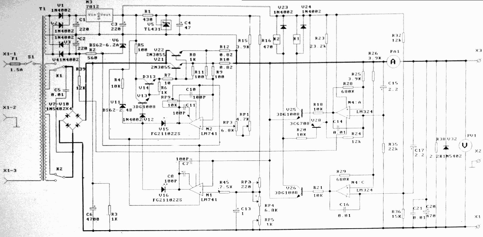
T1 1N4M8B2 C1 228 U5 TL431 R1 47 U6 BS62-6.2A R5 100 2N3855 R8 1K U41M48B2 568 R39 12K R4 10K U14 R10 100 U13 3DG100B RP9 C10 100P U12 1N4M8B2 U15 FG211022S N2 LM741 R11 100 R12 0.82 R15 3.9K R16 470 U23 1N4M8B2 U24 1N4M8B2 R23 23.2k R26 3.9K PA1 A C15 2.2 U25 3DG100B R18 10K U24 LM324 R25 3.9K R20 0.81 R24 12k N4 A C17 2.2 U26 LM324 R29 600K R35 22k R38 U32 V1 1N54D2 X2 R36 15K C21 0.01 C28 470 X1 R45 7.5K RP3 6.8K N1 LM741 C8 100P U16 FG211022S
in „Anderes Labornetzteil“ · Analoge Elektronik und Schaltungstechnik · · Schaltpläne
-
PDF
LN526.pdf
Anode D2 Common Cathode D2 14 Common Anode D1 Common Cathode D1 15 Cathode b1 Anode b1 16 Cathode a1 Anode a1 17 Cathode g1 Anode g1 18 Cathode f1 Anode f1 Absolute Maximum Ratings (T = 25°C) a Lighting Color P DmW) IF(mA) IFPmA) V RV) Topr(°C) T stg) Red 60 20 100 5 25 + 80 30 + 85 Green 60 20 100
in „(VS) Verschenke 75 Stück LN526RK (CK) Led 7-Segment-Displays (NOS)“ · Markt ·
-
PDF
VND830SP.pdf
C = 100 pF) – INPUT 4000 V VESD – STATUS 4000 V – OUTPUT 5000 V – V CC 5000 V Maximum switching energy EMAX (L = 1.8 mH; RL= 0 Ω; Vbat= 13.5 V; jstart150 °C; 100 mJ IL= 9 A) Ptot Power dissipation C = 25 °C 73.5
in „[V] Highside-Schalter“ · Markt ·
-
PDF
TFTNY263PN-TO-TNY268GN_E.pdf
Typical Performance Characteristics 1 1.2 1 1.1 2 2 - 0 2 1.0 2 ) P ) P e C y ° a ° n 5 l 2 e 20.8 o o u t V t e d n e1.0 F e0.6 o iz t l d a u a a m t r0.4 e r u o B N O ( ( 0.2 0.9 0 -50 -25 0 25 50 75 100 125 150 -50 -25 0 25 50 75 100 125 Junction Temperature (°C
in „Neff Steuerplatine Leiterbahnen abgerissen.“ · Platinen ·
-
PDF
PDFsam_panasonic_rf-d10eb_service_manual.pdf
E E H C R 5 KEY0 C515 1000P F 1 1 E _ B_ _ O _ S G C 0 9 RL114 KEY0 D-AMP NC 12 1 C C 100 C501 R 0 H T T V P E V R L 5 5 CIRCUIT A L D Y _ T T T P T T L A _ K C R C514 1000P RL113 KEY_POW (CN601) NC 13 1 D C C K A O O O M U O C
in „Welche Fritzbox hat die meisten Spannungswandler?“ · Analoge Elektronik und Schaltungstechnik ·
-
PDF
sensors-09-04615.pdf
obtained for each photodiode (in the same order as that shown in Table 1): I = 1000 W 7.34 10 m 0.34 A = 2.49 10 A3 (1) p1 m 2 W I = 1000 W 5 ×0 m 0.15 A = 7.5×10 A3 (2) p2 m 2 W W A Ip3= 1000 15 ×0 m 0.21 =3.15 ×0 A−3 (3) m 2 W W A Ip4 =1000 12.96 ×0 m 0.22 = 2.85 ×0 A−3 (4) m 2 W As it might be expected
in „Sonnenscheindauer Sensor selber bauen Eigenbau ATmega Assembler“ · Projekte & Code ·
-
PDF
obC16x.pdf
ist aber bei einem Mikrocontrollersystem normalerweise nicht der Fall. Trotzdem ist eine ¨ solche P¨ufung sinnvoll, weil man nicht vorhersehen kann, was bei einer Uberschreitung der Array–Grenzen passiert. Mit der Compileroption “dbn” mit n > 1 kann u.a. solch eine Uberpr¨fung aktiviert werden (s.
in „Ein kleiner Oberoncompiler für die C16x-Familie“ · Projekte & Code ·
-
PDF
MAC97A6_8.pdf
Current AfterT2+G- dT/dt 50 A/µs TriggeringTM =1.0A,GI =0.2A,GdI /dt=0.2A/µs) T2-G- 50 A/µs T2-G+ 10 A/µs Peak Gate Voltage [ t=2µs (max) ] V GM 5 V Peak Gate Current [ t=2µs (max) ] I 1 A GM Peak Gate Power [ t=2µs (max) ] P GM
in „Blitzbirnen über Funk auslösen (Photographie)“ · Analoge Elektronik und Schaltungstechnik ·
-
PDF
AF143086415692en-000101.pdf
., Secop compressors produced for Danfoss has transcended the barriers for mobile refrigeration. * P Compressors Capacity [W] at max. speed **** a R134a EN12900 Household/CECOMAF | ASHRAE e R404A/R507 * Evaporating temperature [°C] f R600a **, R290 *** r -40 -35 -30 -25 -23.3 -20 -15 -10 -5 0 5 7.2
in „Kompressor für Campingkühlschrank - elektrischer Anschluss?“ · Fahrzeugelektronik ·