
-
PDF
nRF24L01_.pdf
C6,01,94,62,EB,46 0,40,40,AE,84,98,68,24,5E,39,BC,22,11,25,25,80,8C,D4,72,35,10,C0,68,F8,68 Key: E35461346FF083B3CB9941C814AD0E54 T40X:00,40,16,AE,84,98,68,24,5E,39,BC,22,11,25,25,80,8C,D4,72,35,10,C0,68
in „Repeating und Routing Netzwerk mit Arduino und nRF24L01+“ · Projekte & Code ·
-
Datei
LCD.S
- ASCII in decimal - character .byte 0x00,0x00,0x00,0x00,0x00,0x00 ; 00 .byte 0x30,0x21,0x2C,0x21,0x30,0x00 ; 01 .byte 0x60,0x21,0x2C,0x21,0x60,0x00 ; 02 .byte 0x18,0x3C,0x78,0x3C,0x18,0x00 ; 03 .byte 0x08,0x1C,0x3E,0x1C,0x08,0x00 ; 04 .byte 0x00,0x24,0x3A,0x24,0x00,0x00 .byte 0x00,0x0C,0x3E
in „Z Pointer unter AVR GCC setzen“ · Mikrocontroller und Digitale Elektronik ·
-
 Bild
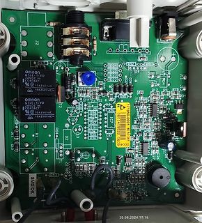
Nahaufnahme einer bestückten grünen Leiterplatte
OMRON GSLE-1-VD 24VDC CONTACT 10A250VAC, J2, R18, D24, D25, D23, D22, R32, R91, R19, R12, R34, R13, R23, R24, R25, R26, R27, R28, R29, R30, R31, R33, R35, R36, R37, R38, R39, R40, R41, R42, R43, R44, R45, R46, R47, R48, R49, R50, R51, R52, R53, R54, R55, R56, R57, R58, R59, R60, R61, R62, R63, R64, R65, R66, R67, D18, D17, D11, D10, K1, K2, T1, T2, C15, C16, J10, J11, J12, J14, J15, J16, J17, J18, J19, J20, J21, J22, J23, J24, J25, J26, J27, J28, J29, J30, J31, J32, J33, J34, J35, J36, J37, J38
in „Hubtisch defekt, Bauteil identifizieren“ · Analoge Elektronik und Schaltungstechnik · · Platinenfotos
-
PDF
S5_-_95U_Anleitung.pdf
Digitalein> u. >ausg§nge > zus. max. 448 Lastspannung L+ Analogein> u. >ausg§nge > zus. max. 32 > Nennwert 24 V DC > zul§ssiger Bereich 20...30 V DC Zul§ssige Bausteine: Organisationsbausteine 1, 3, 13, 21, 22, 31,(einschl. Welligkeit) Ausgangsstrom b.Signal ”1” max. 0.5 A bei 34, 251 60° C Programmbausteine
in „SPS Eingänge werden regelmäßig beschädigt“ · Mikrocontroller und Digitale Elektronik ·
-
Datei
DDS_Jesper.txt
28,30,31,32,34,35,36,38 .DB 39,41,42,44,45,47,48,50 .DB 51,53,54,56,58,59,61,62 ; ; ; ; Output frequency (using 24 bit accumulator) : ; ; f = deltaPhase * fClock/2^24 ; ; fClock is in this case the CPU clock divided by the ; number of cycles to output the data ( 9 cycles ) ; ; f = r24/r25/r26 * (11059200/9)/16777216
in „Probleme mit DDS (Jespers)“ · Mikrocontroller und Digitale Elektronik ·
-
Datei
pwmtest.asm
------------------------- ;rpm= const/step ; ;const=clock*2*60/VorteilerTimer ;const=10000000*2*60/64=4687500 (Hex: 47 86 8c); ; ;Timersteps in cl und ch legen ;Ergebnis in al, ah step_to_rpm: ldi r16, 0x8c mov al, r16 ldi r16, 0x86 mov ah, r16 ldi r16, 0x47 mov bl, r16 ldi r16, 0x9e mov cl, r16 ldi
in „Timing Problem“ · Mikrocontroller und Digitale Elektronik ·
-
PDF
harman_kardon_avr145_sm.pdf
127 AVR145 harman/kardon 128 AVR145 harman/kardon 129 AVR145 harman/kardon 130 AVR145 harman/kardon M24C64 M24C32 64Kbit and 32Kbit Serial I²C Bus EEPROM FEATURES SUMMARY 2 ■ Two-Wire I C Serial Interface Figure 1. Packages Supports 400kHz Protocol ■ Single Supply Voltage: – 4.5 to 5.5V for M24Cxx – 2.5
in „Relais beim AVR 145 von harman/kardon durch SSR ersetzen“ · Analoge Elektronik und Schaltungstechnik ·
-
Datei
main.c
Rate #define USART0_RX_BUFFER_SIZE 32 // define Receive Buffer Size. Size can be 2, 4, 8, 16, 32, 64, 128 or 256 Byte #define USART0_TX_BUFFER_SIZE 64 // define Transmit Buffer Size. Size can be 2, 4, 8, 16, 32, 64, 128 or 256 Byte #define F_CPU 20000000 #include "usart.h" #include <util/delay.h> const
in „Pollin MOTOROLA VIP1710“ · Mikrocontroller und Digitale Elektronik ·
-
Datei
LON.ino
, 0x6A37, 0x7A16, 0x0AF1, 0x1AD0, 0x2AB3, 0x3A92, 0xFD2E, 0xED0F, 0xDD6C, 0xCD4D, 0xBDAA, 0xAD8B, 0x9DE8, 0x8DC9, 0x7C26, 0x6C07, 0x5C64, 0x4C45, 0x3CA2, 0x2C83, 0x1CE0, 0x0CC1, 0xEF1F, 0xFF3E, 0xCF5D, 0xDF7C, 0xAF9B, 0xBFBA, 0x8FD9, 0x9FF8, 0x6E17, 0x7E36, 0x4E55, 0x5E74
in „LON Bus Windhager mitlesen/steuern“ · Softwareentwicklung ·
-
PDF
nRF24LE1_Product_Specification_rev1_6-6439.pdf
Figure 63. SPI Modes 1 and 3: clockPhase = ‘1’. One byte transmission. SPI timing is given in Figure 64. and in Table 90. and Table 91. Revision 1.6 152 of 196 nRF24LE1 Product Specification Tcwh xCSN Tcc Tch Tcl Tcch xSCK Tdh Tdc xMOSI C7 C6 C0 Tcsd Tcd Tcdz xMISO S7 S0 Figure 64. SPI timing diagram.
in „Projekt: Kugelschreiber-Morse“ · Mikrocontroller und Digitale Elektronik ·
-
PDF
UserGuide_MSP430x2xx_slau144e.pdf
complete instruction set is summarized in Table 3−17. Figure 3−20. Core Instruction Map 000 040 080 0C0 100 140 180 1C0 200 240 280 2C0 300 340 380 3C0 0xxx 4xxx 8xxx Cxxx 1xxx RRC RRC.B SWPB RRA RRA.B SXT PUSH PUSH.BCALL RETI 14xx 18xx 1Cxx 20xx JNE/JNZ 24xx JEQ/JZ 28xx JNC 2Cxx JC 30xx JN 34xx JGE 38xx
in „Grundlagen UART: TX & RX Fehler“ · Mikrocontroller und Digitale Elektronik ·
-
PDF
U2651-90011_1_.pdf
environmental requirements for this instrument. Environmental conditions Requirements Operating temperature 0 °C to +55 °C Operating humidity 15% to 85% RH non-condensing Storage temperature –20 °C to 70 °C The U2600A Series USB Isolated Digital Input/Output Modules complies with NOTE the following safety and EMC
in „externe Spannungsversorgung nötig?“ · Mikrocontroller und Digitale Elektronik ·
-
PDF
U2651-90011.pdf
environmental requirements for this instrument. Environmental conditions Requirements Operating temperature 0 °C to +55 °C Operating humidity 15% to 85% RH non-condensing Storage temperature –20 °C to 70 °C The U2600A Series USB Isolated Digital Input/Output Modules complies with NOTE the following safety and EMC
in „Keysight U2600A Series USB Isolated Digital Input/Output Modules“ · Mikrocontroller und Digitale Elektronik ·
-
PDF
8866607431710.pdf
VDE0811 AUFBAU Leiter: El-Cu-Litze, :7 x 0,127 mm => 0,09 mm², AWG 28 verzinnt, Isolation: PVC 105°C, bleifrei Farben : optional(Standard: grau RAL 7032) Seitenstreifen : rot Min. Wanddicke : 0,178 mm Mittl. Wanddicke : 0,24 mm Raster : 1,27 + 0,05 mm Ø : 0,93 + 0,05 mm Steghöhe : 0,23 + 0,05 mm Shorehärte
in „Wieviel Strom über Flachbandkabel“ · Analoge Elektronik und Schaltungstechnik ·
-
PDF
1849588.pdf
from the USB upstream port SMBus Slave Port Indicate the maximum current required for the hub 64-Pin (9x9 mm) QFN lead-free, RoHS compliant controller package Support Custom String Descriptor up to 31 characters Supports industrial temperature range of -40ºC to in length for: 85ºC – Product
in „[V] 2St. 7fach USB2.0 Hub Baustein Microchip/SMCS USB2517-JZX QFN64 (5€)“ · Markt ·
-
PDF
1849588.pdf
from the USB upstream port SMBus Slave Port Indicate the maximum current required for the hub 64-Pin (9x9 mm) QFN lead-free, RoHS compliant controller package Support Custom String Descriptor up to 31 characters Supports industrial temperature range of -40ºC to in length for: 85ºC – Product
in „[V] 2St. 7fach USB Hub Baustein Microchip/SMCS USB2517-JZX QFN64“ · Markt ·
-
PDF
PL68K12.pdf
betriebsbereit und stellen geringe Ansprüche an die Batteriepufferung. EEPROM (optional): Es können Bausteine ST24C02, ST24C04, ST24C08 und gleichwertige anderer Hersteller (Xicor) von 256 bis 1024 Byte verwendet werden, die über den IIC-Bus ansprechbar sind. Die Basisadresse auf dem IIC-Bus ist 0xA8. Die Bausteine
in „S: 68000/68HC000/68EC000/68001 CPUs min. 12MHz“ · Markt ·
-
PDF
PL68K12.pdf
betriebsbereit und stellen geringe Ansprüche an die Batteriepufferung. EEPROM (optional): Es können Bausteine ST24C02, ST24C04, ST24C08 und gleichwertige anderer Hersteller (Xicor) von 256 bis 1024 Byte verwendet werden, die über den IIC-Bus ansprechbar sind. Die Basisadresse auf dem IIC-Bus ist 0xA8. Die Bausteine
in „[S] MPU (Z80/6502/68k)“ · Markt ·
-
Datei
strace.txt
3 read(3, "\177ELF\1\1\1\0\0\0\0\0\0\0\0\0\3\0\3\0\1\0\0\0 \243\1\0004\0\0\0"..., 512) = 512 fstat64(3, {st_mode=S_IFREG|0644, st_size=2287824, ...}) = 0 mmap2(NULL, 2292076, PROT_READ|PROT_EXEC, MAP_PRIVATE|MAP_DENYWRITE, 3, 0) = 0xb7532000 mprotect(0xb775c000, 4096, PROT_NONE) = 0 mmap2(0xb775d000
-
Datei
Offset.txt
0D 26 00 03 17 41 30 03 30 8A 0A 14 0D 15 00 03 08 72 {69} 19:49:28 06.01.11: 08 00 18 00 5A 01 E8 64 00 00 01 64 60 80 00 01 D4 01 C9 00 00 0E 30 41 01 31 FF 01 00 69 {E4} 19:49:38 06.01.11: 08 10 10 30 32 4C 01 0A 8A 06 09 0F 0D 00 00 00 E4 {1E} 19:49:38 06.01.11: 10 88 10 3C 1B 1E {FE} 19:49:38 06.01.11
-
PDF
Hardware.pdf
R 4 22-27-2031-03 9 D 9 D + 1 20 BSL_EN J11-1 R R 63 DVCC1 P2.0 21 +3V3 L L DVSS1 P2.1 22 J11-2 L1 64 P2.2 23 BSL_RX D R R D AVCC P2.3 PWM1 N J11-3 2 0 3 0 742792641 N 62 AVSS P2.4 24 ICL G R 1 R 1 G P2.5 25 ACP 7 VREF+ P2.6 26 FAULT 10 VEREF+ P2.7 27 FLAG 11 VREF-/VEREF- R4 T1 C1 C2 C3 C4 C5 C6 P3.0
in „74HCT595 + ULN2003 an 5V und 12V problem“ · Mikrocontroller und Digitale Elektronik ·
-
Datei
Display3310-Nokia.bas
&H44 , &H00 , &H00 , &H41 , &H7F , &H40 , &H00 , &H00 , &H7C , &H04, Data &H18 , &H04 , &H7C , &H00 , &H7C , &H08 , &H04 , &H04 , &H78 , &H00 , &H38 , &H44 , &H44 , &H44 , &H38 , &H00, Data &H7C , &H14 , &H24 , &H24 , &H18 , &H00 , &H18 , &H24 , &H24 , &H14 ,
in „Bascom u. SPI und Soft-SPI“ · Mikrocontroller und Digitale Elektronik ·
-
PDF
IRF3708PBF.pdf
Source Current integral reverse G ––– ––– 248 S (Body Diode) p-n junction diode. ––– 0.88 1.3 V T J 25°C, IS= 31A, VGS= 0V VSD Diode Forward Voltage ––– 0.80 ––– T = 125°C, I = 31A, V = 0V J S GS rr Reverse Recovery Time ––– 41 62 ns T J 25°C, IF= 31A, VR=20V Q Reverse Recovery Charge ––– 64 96 nC di/dt
in „Transistor zum Schalten von 24V/12V“ · Analoge Elektronik und Schaltungstechnik ·
-
PDF
IRF3708_IR__1_.pdf
Source Current integral reverse G ––– ––– 248 S (Body Diode) p-n junction diode. ––– 0.88 1.3 V T J 25°C, IS= 31A, VGS= 0V VSD Diode Forward Voltage ––– 0.80 ––– T = 125°C, I = 31A, V = 0V J S GS rr Reverse Recovery Time ––– 41 62 ns T J 25°C, IF= 31A, VR=20V Q Reverse Recovery Charge ––– 64 96 nC di/dt
in „Mosfet Treiberschaltung“ · Mikrocontroller und Digitale Elektronik ·
-
PDF
IRF3708_IR__1_.pdf
Source Current integral reverse G ––– ––– 248 S (Body Diode) p-n junction diode. ––– 0.88 1.3 V T J 25°C, IS= 31A, VGS= 0V VSD Diode Forward Voltage ––– 0.80 ––– T = 125°C, I = 31A, V = 0V J S GS rr Reverse Recovery Time ––– 41 62 ns T J 25°C, IF= 31A, VR=20V Q Reverse Recovery Charge ––– 64 96 nC di/dt
in „24V-Ausgang potentialgetrennt aus einem STM32 3,3V“ · Mikrocontroller und Digitale Elektronik ·
-
PDF
GU256X64-372.pdf
Dot Graphic VFD Module GU256x64-372 ! 256 x 64 Dot Graphic The module includes the Vacuum Fluorescent Display ! Operating Temp -0 C°to +50 C ° glass, driver and control ASIC, with refresh RAM, character ! Single 5V Supply. generator
-
PDF
dmf5000.pdf
View Maximum Ratings Input Voltage 26.4VDC Output Power Consumption5W Storage Temperature -20 - 75 °C Operating Temperature 0 - 50 °C Acceptable Operating Range Input Voltage 24±1.2VDC 3. Interface 3.1 Interface Connection DMF 5001N, 5002N, 5003N Series Pin No. Symbol Level Function 1 FG - Frame Ground
in „Optrex DMF50126“ · Mikrocontroller und Digitale Elektronik ·
-
PDF
dmf5000.pdf
View Maximum Ratings Input Voltage 26.4VDC Output Power Consumption5W Storage Temperature -20 - 75 °C Operating Temperature 0 - 50 °C Acceptable Operating Range Input Voltage 24±1.2VDC 3. Interface 3.1 Interface Connection DMF 5001N, 5002N, 5003N Series Pin No. Symbol Level Function 1 FG - Frame Ground
-
PDF
ml50x_schematics.pdf
HDR2_44_SM_14_P TRC_CLK 8 7 MICTOR_5 55 56 HDR2_56_SM_13_P 28 GPIO_LED_4 HDR1_50 A22 B22 NC 6 5 NC C 57 58 HDR2_58_SM_4_N 29 NC HDR1_52 A23 B23 HDR1_54 NC 4 3 NC C 59 60 HDR2_60_SM_4_P 30 NC VCC3V3 A24 B24 HDR1_56 2 1 61 62 HDR2_62_SM_9_N 31 IIC_SCL_EXP HDR1_58 A25 B25 63 64 HDR2_64_SM_9_P 32 IIC_SDA_EXP
in „DDR2 RAM Ansteuerung mit Virtex-5 ML507“ · FPGA, VHDL & Co. ·
-
PDF
STC89C51RC-en.pdf
to Carry 2 24 12 ANL C, /bit AND complement of direct bit to Carry 2 24 12 ORL C, bit OR direct bit to Carry 2 24 12 ORL C, /bit OR complement of direct bit to Carry 2 24 12 MOV C, bit Move direct bit to Carry 2 12 6 MOV bit, C Move Carry to direct bit 2 24 12 JC rel Jump if Carry is set 2 24 12 JNC rel Jump if Carry not set 2 24 12 JB bit, rel Jump if direct bit is set 3 24 12 JNB bit,rel Jump if direct bit is not set 3 24
in „stc89c52rc programmieren“ · Mikrocontroller und Digitale Elektronik ·
-
Datei
Compile-SPFT-with-qtcreator-Libs-Info.txt
/usr/lib64/libstdc++.so.6 (0x00007f4c4485c000) libm.so.6 => /lib64/libm.so.6 (0x00007f4c4455f000) libgcc_s.so.1 => /lib64/libgcc_s.so.1 (0x00007f4c44348000) libc.so.6 => /lib64/libc.so.6 (0x00007f4c43fa7000) /lib64
in „SP-Flash-Tool Compilieren mit QtCreator - Problem“ · Softwareentwicklung ·
-
PDF
ADA2200-EVALZ_UG-702.pdf
1 1 1 1 1 1 1 A0 1 1 8 8 7 F 2 7 1 µ A1 2 7 C 0 3 3 6 6 SCL 4 4 5 5 SDA 4 k 6 k R 1 R 1 110-43-308-41-001000 6 0 DIP-8 EEPROM SOCKET - EEPROM TO BE INSTALLED: 9 AT24C02C-PUM 3 2 (8-LEAD PDIP OR EQUIVALENT) 1 Figure6.ADA2200-EVALZSchematic Rev. 0
in „Lock In Verstärker; Vibrometer“ · Analoge Elektronik und Schaltungstechnik ·
-
PDF
ts912.pdf
10 5 2 5 1 HSCP 68 25 VSCP1 0.8E8 EIN 16 5 1 5 1 DON 69 19 MDTH 400E-12 RIP 10 11 6.500000E+00 VON 24 5 1.7419107 RIN 15 16 6.500000E+00 HSCN 24 69 VSCN1 0.8E+08 RIS 11 15 1.271505E+01 VSCTHP 60 61 0.0875 DIP 11 12 MDTH 400E-12 ** VSCTHP = le seuil au dessus de vio * 500 DIN 15 14 MDTH 400E-12 ** c.a.d
in „"Hallsonde für Oszilloskop" im Eigenbau?!“ · Analoge Elektronik und Schaltungstechnik ·
-
PDF
BMP280_2018.pdf
T = (t_fine * 5 + 128) >> 8; return T; } // Returns pressure in Pa as unsigned 32 bit integer in Q24.8 format (24 integer bits and 8 fractional bits). // Output value of “24674867” represents 24674867/256 = 96386.2 Pa = 963.862 hPa BMP280_U32_t bmp280_compensate_P_int64(BMP280_S32_t adc_P) { BMP280_
in „BME680 Berechnung Temperatur Luftfeuchtigkeit Druck Gas Fragen Initialisierung Assembler ASM ATmega8“ · Mikrocontroller und Digitale Elektronik ·
-
PDF
UPC1676G.pdf
test procedures en- sure the highest reliability and performance. ELECTRICAL CHARACTERISTICS (TA= 25°C, VCC= 5 V, f = 500 MHz) PART NUMBER UPC1676B 1 UPC1676G UPC1676P PACKAGE OUTLINE B08 39 CHIP SYMBOLS PARAMETERS AND CONDITIONS UNITS MIN TYP MAX MIN TYP MAX MIN TYP MAX CC SupplyCurrent mA 14 19 24 14
in „ATmega8. Umbau als 2GHz Frequenz-Logger“ · Mikrocontroller und Digitale Elektronik ·
-
Datei
10.4._0646_uhr_TX_2475__RX_2403_2423_2440.txt
0C 00 09:49:23 So 220410 2 01 00 01 01 46 00 55 01 15 01 54 00 32 00 A8 00 00 5C 00 2 02 86 16 00 00 79 51 00 1E 00 12 08 F5 13 8E 01 AA E8 00 1 83 00 00 00 13 03 E8 00 7C 00 01 A3 08 38 8E 09:50:24 So
in „Wechselrichter Hoymiles HM-xxxx 2,4 GhZ Nordic Protokoll?“ · Mikrocontroller und Digitale Elektronik ·
-
PDF
st7920_chinese_font_controller.pdf
-1188 63 C[24] 1694 -1933 64 C[25] 1819 -1933 26 D2 -2548 -1312 27 D3 -2548 -1438 65 C[26] 1944 -1933 28 D4 -2548 -1562 66 C[27] 2069 -1933 29 D5 67 C[28] 2194 -1933 -2548 -1688 30 D6 -2548 -1812 68 C[29] 2319
-
PDF
st7920_chinese.pdf
-1188 63 C[24] 1694 -1933 64 C[25] 1819 -1933 26 D2 -2548 -1312 27 D3 -2548 -1438 65 C[26] 1944 -1933 28 D4 -2548 -1562 66 C[27] 2069 -1933 29 D5 67 C[28] 2194 -1933 -2548 -1688 30 D6 -2548 -1812 68 C[29] 2319
-
PDF
RXV667.pdf
1uF 25V C62 US063100 C.CE.CHP 1000pF 50V B C349-350 US135100 C.CE.CHP 0.1uF 16V C63-64 US135100 C.CE.CHP 0.1uF 16V C351 WG251600 C.CE.CHP 4.7uF 6.3V C65 WD758300 C.CE.CHP 10uF 10V * C352 WP092800 C.EL.CHP 22uF
in „Yamaha RX-V667 Reparatur und Bezugsquellen?“ · Analoge Elektronik und Schaltungstechnik ·
-
PDF
pck_062.pdf
Q21 CON3 - V IRFZ24 R72 LM324 1 R78 C88 1k Cext1 1 10k 100n C21 10n + C29 100n 100u C20 100n MMA_mode R31 10k D1 R95 B B Disable_Power Lichtbogen R87 R83 gezündet Q19 Q7 DIODE 10k + C76 Q1 4,7uF C38 S8050 S8050 MK1_7 100n
in „Umbau Stahlwerk Wig 200puls + Plasma“ · Mechanik, Gehäuse, Werkzeug ·
-
Datei
report.txt
13:40:45 D:\Projects\Sn\Bastelkram\Pioneer PDP505\report.txt BLOCK 0 VESA 0 1 2 3 4 5 6 7 8 9 A B C D E F ---------------------------------------------------------------- 00 | 00 FF FF FF FF FF FF 00 34 38 93 17 C6 02 00 00 10 | 06 0F 01 03 80 80 5A 96 EE 26 95 9C 57 4C 96 26 20 | 10 50 54 00 87 00
in „DVI-EDID Problem, Monitor wird nicht erkannt“ · Mikrocontroller und Digitale Elektronik ·
-
Datei
motor_an_und_kurbel_schneller_drehen.txt
, 0x00 , 0x2C , 0x3F , 0x01 , torque: -1 -1 1 pos: 64 speed: 319 backwards: 0 lost: 0 0 0 0 error: 2C alive: 0 0x36 , 0xE3 , 0x00 , 0xE0 , 0x40 , 0xC7 , 0x00 , 0x2C , 0x3F , 0x01 , torque: -2 -1 -1 pos: 64 speed:
in „oszi gemessen -> 31428 baud?“ · Mikrocontroller und Digitale Elektronik ·
-
PDF
irf3708.pdf
Units Conditions gfs Forward Transconductance 49 ––– ––– S VDS= 15V, D = 50A Qg Total Gate Charge ––– 24 ––– D = 24.8A Qgs Gate-to-Source Charge ––– 6.7 ––– nC VDS= 15V Qgd Gate-to-Drain ("Miller") Charge ––– 5.8 ––– VGS = 4.5VR Qoss Output Gate Charge ––– 14 21 VGS = 0V,DI = 24.8A,DS = 15V td(on) Turn-On
in „IRF3708 als Schalter“ · Mikrocontroller und Digitale Elektronik ·
-
PDF
Datenblatt_SAB-C167CR-LM_SiemensSemiconductorGroup.pdf
RDising t21 SR – 15 + tF – TCL – 10 ns edge (no RW-delay )1) + 2A + F 1) Data valid to WR t22 CC 25 + tC – 2TCL – 25 – ns + t C Data hold after WR t24 CC 15 + tF – TCL – 10 + F – ns Semiconductor Group 54 C167CR Parameter Symbol Max. CPU Clock Variable CPU Clock Unit = 20 MHz 1/2TCL = 1 to 20 MHz min. max
in „Ersatz für alten Hitach H8/3337 µP?“ · Mikrocontroller und Digitale Elektronik ·
-
PDF
SH1106_V2.3.pdf
VDD2 VSS VCOMH VCL Segment driver Common driver V SL Power supply circuit IREF Shift register V PP C1N C1P Charge Pump C2N Display data latch C2P r r s VBREF i d g c c e r c d n n Output status e 132 X 64-dots s o l selector circuit f Display Data RAM r c l b d i s / a L d I n i l n I Column address
-
PDF
SH1106.pdf
VDD2 VSS VCOMH VCL Segment driver Common driver V SL Power supply circuit IREF Shift register V PP C1N C1P Charge Pump C2N Display data latch C2P r r s VBREF i d g c c e r c d n n Output status e 132 X 64-dots s o l selector circuit f Display Data RAM r c l b d i s / a L d I n i l n I Column address
in „SH1106 Init-Sequenz“ · Mikrocontroller und Digitale Elektronik ·
-
PDF
TPSchalter_KM_G_020322.pdf
M M M G G G G G G G G G G 1 1 1 1 1 1 1 1 1 2 2 2 2 2 2 2 2 2 2 3 3 1 controllereinheit des Trans- C C C C S S S S S S S S S S E E E E E E E E E E E E E E E E E E E E E ponder-Sicherheitsschalters 8 9 S S S S S S S S S S S S S S S S S S S S S S C11 C10 IC3 IC1 24C08 ELV01205 IC1 Microcontroller 4 100n
in „Transponder Lesegerät SUCHE LÖSUNG ???“ · Mikrocontroller und Digitale Elektronik ·
-
PDF
LGDP4524.pdf
Display size Lines Driven gate lines 00h Setting disabled 01h 528 x 16 dots 16 G1 to G16 02h 528 x 24 dots 24 G1 to G24 03h 528 x 32 dots 32 G1 to G32 04h 528 x 40 dots 40 G1 to G40 05h 528 x 48 dots 48 G1 to G48 06h 528 x 56 dots 56 G1 to G56 07h 528 x 64 dots 64 G1 to G64 08h 528 x 72 dots 72 G1 to
in „LCD farben invertiert normal ?“ · Mikrocontroller und Digitale Elektronik ·
-
PDF
slau144j.pdf
is shown in Figure 3-12 and the complete instruction set is summarized in Table 3-17. 000 040 080 0C0 100 140 180 1C0 200 240 280 2C0 300 340 380 3C0 0xxx 4xxx 8xxx Cxxx 1xxx RRC RRC.B SWPB RRA RRA.B SXT PUSH PUSH.B CALL RETI 14xx 18xx 1Cxx 20xx JNE/JNZ 24xx JEQ/JZ 28xx JNC 2Cxx JC 30xx JN 34xx JGE
in „MSP430 Gleitkommazahl in Flash speichern“ · Mikrocontroller und Digitale Elektronik ·
-
PDF
family_guide.pdf
is shown in Figure 3-12 and the complete instruction set is summarized in Table 3-17. 000 040 080 0C0 100 140 180 1C0 200 240 280 2C0 300 340 380 3C0 0xxx 4xxx 8xxx Cxxx 1xxx RRC RRC.B SWPB RRA RRA.B SXT PUSH PUSH.B CALL RETI 14xx 18xx 1Cxx 20xx JNE/JNZ 24xx JEQ/JZ 28xx JNC 2Cxx JC 30xx JN 34xx JGE
in „MSP430 Output nur auf zwei von vier Pinnen möglich?“ · Mikrocontroller und Digitale Elektronik ·
