-
PDF
at90can-v1.1.pdf
1MHz 3 LM5001MA/NOPB 25k ~ 500kHz R 1µ/10V 129k ~ 100kHz GND GND GND D2 VUSB VIN P DFLS240 2 1 T 3 2 1 5 3 JP10 + + IC11 Q1 D3 IRLML5203 1 IN OUT 5 VCAN0 S D C DFLS240 P C16 3 EN C 2 R11 G 2 1 T +C15 1µ/10V 2 GND NC/FB 4 10k
-
PDF
Cinni-Regler_V1-1a-Partlist.pdf
SMD 10k R1206 2 Reichelt SMD 1/4W 10K 0,082 € 0,082 € R17 1 Widerstand SMD 10k R1206 2 Reichelt SMD 1/4W 10K 0,082 € 0,082 € R18 1 Widerstand SMD 10k R1206 2 Reichelt SMD 1/4W 10K 0,082 € 0,082 € R19 1 Widerstand SMD 2k2 R1206 2 Reichelt SMD 1/4W 2,2K 0,082 € 0,082 € R20 1 Widerstand SMD 3k3 R1206 2 Reichelt SMD 1/4W 3,3K 0,082 € 0,082 € R21 1 Widerstand SMD 2k2 R1206 2 Reichelt SMD 1/4W 2,2K 0,082 € 0,082 € R22 1 Widerstand
in „Vorstellung Drehzahlregler mit Triac in Steckergehäuse“ · Mikrocontroller und Digitale Elektronik ·
-
PDF
VA3DIW__Vackar_VFO__Vackar_oscillator_2160103.pdf
sine wave. The reconstruction filter is not there. If you want phase noise of -80dBc/Hz @10kHz and worse, use the DDS. Careful observation of the oscillator performance reveals well-known issue, the limited dynamic range and S/N ratio of HP Spectrum Analyzers. Compare with Rohde & Schwarz. The
-
PDF
statron3257.pdf
schraub-/steckbar 4mm Sicherheitsbuchsen max. relative Luftfeuchte 85% bei 35°C AC Eingangsspannung 230 V +6 / -7% 48-62Hz AC Prüfspannungen Eing.-Masse1,5kV; Prim.-Sek.1,5kV; Ausg.-Masse 500VAusgang-Masse 1000V Schutzklasse und -grad I / IP30 gefertigt nach DIN VDE 0551 ; DIN VDE 0875 Teil 11 Kurve B
in „[V] Statron 3257.1 36V/40A 1440W lineares Netzgerät NEU“ · Markt ·
-
PDF
Power_Supply_PCB_Assembly.pdf
SCREW M3X10 3 4mH 4 3 4mH 4 1W TP5 13 0024371 TH2 J4 230V SCR10 SCK2R515 C15 C16 C17 R7 C87 J2-4 SCREW M3X10 J5 120V 680UF 680UF 680UF 5.1K 0.1UF N T1-A D3 L4 100V 100V 100V 100V ER1002F 2W J2-5 0026672 2 1 11 12 3uH SCR11 SCREW M3X12 J1-2 C4 C3 0026672 TP3
in „Mackie PPM1012 Netzteilfehler“ · Analoge Elektronik und Schaltungstechnik ·
-
PDF
EVI-370-series-brochure-eng.pdf
EVI-370/371 Series CCD camera block 12 ×Optical Zoom, High Speed Auto Focus incorporates a 1/3" (380k/440k effective Lens pixels) CCD. Up to 12 times optical zoom is VISCA /RS-232C Control available throughout the EVI-370/371 series. TM For applications where increased zoom is Continuous Camera Data
-
PDF
2023-04-06_Schematic_ESP32-CAN_draft.pdf
IO0 17 IO1 C10 1k▯' R13 R14 C11 1 2 SW2 TMS_IO4 3 EN IO1 16 IO2 R15 GND 10uF 1k▯' 1k▯' 1uF TS-1187A-B-A-B TDI_IO5 4 IO4 IO2 15 IO3 D11 R16 1k▯' C12 3 4 3V3 IO6_MISO 5 IO5 IO3 14 USB_PROG_P 10k▯' MCP_TXCAN 1 20 B5819W
in „ESP32 C3 Wroom - USB Verschaltung“ · Mikrocontroller und Digitale Elektronik ·
-
PDF
646978.pdf
280 — VS= 0V t Turn-Off Propagation Delay — 225 — V = 1200V off S tsd Shutdown Propagation Delay — 230 — VS= 1200V ns r Turn-On Rise Time — 25 — t Turn-Off Fall Time — 17 — f MT Delay Matching, HS & LS Turn-On/Off — — 30 Static Electrical Characteristics VBIAS (CC , BS, VDD) = 15V,AT = 25°C andSS= COM
in „Wer kann mir was zu diesem Bauteil sagen ?“ · Mikrocontroller und Digitale Elektronik ·
-
PDF
NPX-35TFR-product-data-sheet.pdf
241 9.49 47.13 103.90 1 J/G NP200-12 NP200-12FR 200.0 520 20.47 260 10.24 208 8.19 73.00 160.93 3 K/G ® DATASAFE NPX BATTERY SERIES Type FR Type* Volts Watts/Cell to Nominal Length Width Overall Height Weight Layout Terminal 1.67 End Voltage Capacity incl. Terminals Illustration (20hr rate-Ah) mm (
in „[S] Polschutzkappen für 5.5mm Anschlüsse von Akkus“ · Markt ·
-
PDF
A500_LTV354T.pdf
Resistance 100 10000 V = 20V V CE2V A 50 Ic= 2mA ( Ta= 25 C 1000 ) 20 tr I s tf n e 10 r i 5 td u100 t k s 2 a o ts r s 1 t 10 R e 0.5 o C 0.2 1 0.1 20 40 60 80 100 0.1 0.2 0.5 1 2 5 10 o Ambient Temperature Ta ( C) Load resistance R (k ) Fig.11 Frequency Response Test Circuit for Response Time Input V = 2V Vcc Ic= 2mA Output o Input R D R L Output 10% ) 0 Ta= 25 C B 90% ( td A ts i g R = 1k 1k 100 tr tf e -10 a Test Circuit for Frequency Response o V Vcc RD RL Output -20 0.2 0.5 1 2 5 10 100 1000 Frequency f (kHz) 4 ) *+!, 4 % 7 8 ▯▯ ▯▯ ▯ ▯ ▯ ▯ ▯ " ; #( % # ' 0 ( ( ' 1 1 0 ( ( # 1 ' & #
in „Frage zu Optokopplern“ · Mikrocontroller und Digitale Elektronik ·
-
Datei
hope.c
K3.2 einschalten _delay_ms(400); PORTD &= ~(1<<PD4);// Relais K3.2 auschalten, bleibt angezoagen relais32=1; } } if (Rki>RkiSoll && relais21==0) { RkiFehler=0b00000000; PORTD |= (1<<PD2); // Relais K2.1
in „Atmega88 region text overflowed by 156 bytes“ · Mikrocontroller und Digitale Elektronik ·
-
PDF
MAS1017_MicroAnalogSystems-1.pdf
time signals in the frequency range fromprocessed directly with an additional digital circuitry to kHz to 100 kHz. There are only a few external extract the data from the received signal. components needed. The circuit has a preamplifier, FEATURES APPLICATIONS • Highly Sensitive AM Receiver • Time Signal
in „Reichelt DCF77 Modul schwingt nicht an.“ · Analoge Elektronik und Schaltungstechnik ·
-
Datei
BBS3002-SPICE-D.txt
RB = 0.001 ohm .MODEL BBS3002 PMOS ( LEVEL = 8 +VERSION = 3.2 TNOM = 27 TOX = 6.0E-08 +VTH0 = -2.22 K1 = 3.2 K2 = -0.04 +NLX = 1.70E-07 DVT0 = 1.12 DVT1 = 0.38 +DVT2 = -0.01 U0 = 230 UA = 8.00E-10 +UB = 1.00E-21 VSAT = 1.25E05 A0 = 0.00E00 +AGS = -1.00 A1 = 0 A2 = 1 +RDSW = 8.00E06 PRWG = -0.014 WR =
in „Trennung zweier unterschiedlicher Spannungsquellen“ · Analoge Elektronik und Schaltungstechnik ·
-
PDF
FSP_SHB_D.pdf
zur Messung des Phasenrauschens Offset Span RBW Referenzpegel a FSP 100 Hz 20 Hz 10 Hz 0 dBm 10 dB 1 kHz 200 Hz 100 Hz 0 dBm 10 dB 10 kHz 2 kHz 300 Hz -10 dBm 10 dB 100 kHz 10 kHz 3 kHz -20 dBm 0 dB 1 MHz 100 kHz 30 kHz -20 dBm 0 dB Hinweise: Um eine genaue Messung des Phasenrauschens bei hohen Offsets
-
PDF
DM-KIT-SSK_for_BF533.pdf
TXCATXCAN 1 U4 8 R20 J17 MOSI 2 J7 3V3 0.1uF 1 D CANHS 6 0 GND 3 CON3 D MISOI MISO 7 DO RSV 8 R10120K GND 1 RXCAN 4 R VREF 5 GND 1 D SPI_SCLK 5 RSV 9 TP9 RXCAN SN65HVD230 3V3 SD_SPISS SD_SPISS 1 CSK A R10420K R197 SW 10 SD_INF SD_INF C14 C15 SW 11 120 0.1uF 0.1uF GND 10K5 SDcard Decap GND SD_SPI TXCAN
-
PDF
Anleitung_MULTIMESS96_Light_Basic_1_.pdf
schlossen werden! 3 7 0 D E E 3.4 Bedien- und Anzeigeteil L1 U PH-N / V U PH-PH / V L2 I /NI / A S / kVA P / kW Q / kVar cosϕ L3 Freq. / Hz kWh x 1000 SPEICHER / MEMORY AUSWAHL / MENU MIN MAIN MINN MIN Version 1.00 Seite 7 von 29 Bedienungsanleitung MULTIMESS 96-Light / Basic 3.4.1 Beschreibung der Tasten
in „KBR Multimess 96 / Passender Stromwandler“ · Analoge Elektronik und Schaltungstechnik ·
-
PDF
Anleitung_MULTIMESS96_Light_Basic_1_.pdf
schlossen werden! 3 7 0 D E E 3.4 Bedien- und Anzeigeteil L1 U PH-N / V U PH-PH / V L2 I /NI / A S / kVA P / kW Q / kVar cosϕ L3 Freq. / Hz kWh x 1000 SPEICHER / MEMORY AUSWAHL / MENU MIN MAIN MINN MIN Version 1.00 Seite 7 von 29 Bedienungsanleitung MULTIMESS 96-Light / Basic 3.4.1 Beschreibung der Tasten
in „[S] Stromwandler“ · Markt ·
-
PDF
TKM32F499_______.pdf
3P1U0IU91P8P7 1P5 U4U312P U P998P7 U1U P I U 3 GND MOSI P I U 3 0 5 PIC102 3 PIP203 PA6 Q Q T N T P D S K K C X X 2 K A Q Q 4 3 2 0 9 D Y X X 2 1 Q Q TKM32F499GT8 W25Q32 54 P I P 2 0 4 D S E E O - V V C C L _ _ 1 S S S D P P P P PD / V U _ 3 C C SS D P5 V V T R B V _ S I / / I C C V V Q Q C Q3/K _ 0 R R M M V V / 0 K M _ / K S P P P _P I S K / / / / GND _ _ 1 1 I I S 4 Q Q Q Q S Q 1 / / R X_ I I D I S 4 I S Q P 1 1 N N CO5 COD PIC1302 PIC1301 / / 5 / S S 1 C P P / C/ P6 BHEADSMD1x4 2 0 1 P C P P M C P P R DR B 61
in „TKM32F499 Board mit Display“ · Mikrocontroller und Digitale Elektronik ·
-
PDF
X7R_Datenblatt.PDF
2200 J J J J J J M 3300 J J J J J J M 4700 J J J J J J M 6800 J J J J J J M Cap 0.010 J J J J J J M K K K K M M X X X M P (μF 0.015 J J J J J J P K K K P M M X X X M P 0.022 J J J J J J Q K K K P M M X X X M P 0.033 J J J J J J Q K K K X M M X X X M P 0.047 J J J J J J K K K Z M M X X X M P 0.068 J J J J J M K K K Z M M X X X M P 0.10 J J J J J M K K K Z M M X X X M P 0.15 J J J J M K K P M M X X X M P 0.22 J J J J P K K P M M X X M P 0.33 J J J J Z K M M M X X M P 0.47 M M M M Z K P M M X X M P 0.68 M M P
in „Vielschicht statt Elko + Keramik“ · Analoge Elektronik und Schaltungstechnik ·
-
Datei
ow.c
unsigned char ow_next(unsigned char RomCommand) { unsigned char m = 1; unsigned char n = 0; unsigned char k = 1; unsigned char x = 0; unsigned char discrepMarker = 0; unsigned char g ; unsigned char nxt ; int flag; nxt = FALSE; dowcrc = 0; flag = ow_reset(); if(flag||doneFlag) { lastDiscrep = 0; return FALSE
in „Falsche TEMP mit DS1820“ · Mikrocontroller und Digitale Elektronik ·
-
PDF
EP22_10BaseT1L.pdf
EXPLOSIONS- v SORGUNG ÜBER SCHUTZ MÖGLICH D DATENLEITUNG l n PROFIBUS PA UART/Profibus 1200 m 31,25 kBit/s, Bus, Nein M12, Schraub- Ja : Halb-Duplex klemme l u Modbus RTU und UART/Modbus 1200 m (bis ca. Typisch 19,2 kBit/s, Nein DB9, M12 k.A. Q andere RS485 180 kBit/s, bei Bus, Halb-Duplex Protokolle 375 kBit 300m, bei 500 kBit 200 m IO-Link IO-Link 40 m Max 230,4 kBit/s, Nein M12 Nein Halb-Duplex 4-20 mA Analog-Schnitt- 200 m und mehr -/- Ja, circa 36 mA Schraubklemme Ja stelle HART® Digital moduliert
in „Power und Ethernet über zwei Drähte“ · Analoge Elektronik und Schaltungstechnik ·
-
PDF
ADXL202E.pdf
Noise Density @ 25⬚C X 200 200 1000 µg√Hz rms FREQUENCY RESPONSE 3 dB Bandwidth At Pins FILT YFILT 6 6 kHz Sensor Resonant Frequency 10 10 kHz FILTER RFILTTolerance 32kΩ Nominal ±15 ±15 % Minimum Capacitance At Pins FILT YFILT 1000 1000 pF SELF-TEST Duty Cycle Change Self-Test “0” to “1” 10 10 % DUTYCYCLE
in „Noise Performance“ · Mikrocontroller und Digitale Elektronik ·
-
Datei
ASCIANSI.TXT
h 0105 i 0106 j 0107 k 0108 l 0109 m 0110 n 0111 o 0112 p 0113 q 0114 r 0115 s 0116 t 0117 u 0118 v 0119 w 0120 x 0121 y 0122 z 0123 { 0124 | 0125 } 0126 ~ 0127 0128 0129 0130 0131 0132 0133 0134 0135 0136 0137 0138 0139 0140
in „O-LED Display von SMI“ · Mikrocontroller und Digitale Elektronik ·
-
PDF
Boris_Voyager.sch.pdf
7 XTAL1 17 VCC_3 Q2 S1 S2 S3 S4 S5 C12 100n 38 9 27 VCC PD0 10 RXD_AVR/2.4A 3 1 3 1 3 1 3 1 3 1 6 k AVCC PD1 TXD_AVR/2.4A A R 1 C6 PD2 11 4 2 4 2 4 2 4 2 4 2 A 100n 29 AREF PD3 12 +3V3+3V3 Z1 RESET/2.4A 4 13 +3V3 C1 S6 S7 S8 S9 S10 C7 ~RESET PD4 14 100n 8 PD5 15 2 1 3 1 3 1 3 1 3 1 3 1 0 XTAL1 XTAL1
in „Noch ein Taschenrechner auf ATMega Basis“ · Projekte & Code ·
-
PDF
151998-da-01-en-HCPL7840_Optokoppler.pdf
Circuit. 12 10 K VDD1 V DD2 +15 V 0.1 µF 9 0.1 µF 1 8 DELAY TO 90% 0.1 µF 8 DELAY TO 50% 2 K RISE/FALL TIME VIN 2 7 7 – s HCPL-7840 V OUT µ 2 K – 6 0.01 µF 3 6 + MC34081 E T 5 – t 4 5 0.1 µF 4 V = 5 V 10 K DD1 3 VDD2
in „analoges Signal galvanische Trennung“ · Mikrocontroller und Digitale Elektronik ·
-
PDF
HCPL7840.pdf
Circuit. 12 10 K VDD1 V DD2 +15 V 0.1 µF 9 0.1 µF 1 8 DELAY TO 90% 0.1 µF 8 DELAY TO 50% 2 K RISE/FALL TIME VIN 2 7 7 – s HCPL-7840 V OUT µ 2 K – 6 0.01 µF 3 6 + MC34081 E T 5 – t 4 5 0.1 µF 4 V = 5 V 10 K DD1 3 VDD2
in „Galvanisch getrennte Spannungsmessung“ · Analoge Elektronik und Schaltungstechnik ·
-
PDF
HCPL7840.pdf
Circuit. 12 10 K VDD1 V DD2 +15 V 0.1 µF 9 0.1 µF 1 8 DELAY TO 90% 0.1 µF 8 DELAY TO 50% 2 K RISE/FALL TIME VIN 2 7 7 – s HCPL-7840 V OUT µ 2 K – 6 0.01 µF 3 6 + MC34081 E T 5 – t 4 5 0.1 µF 4 V = 5 V 10 K DD1 3 VDD2
in „Analoge Optokopplung“ · Mikrocontroller und Digitale Elektronik ·
-
PDF
1510fc.pdf
2.441 2.489 V 8V≤ V CC≤ 28V, J < 0°C 2.430 2.489 V Oscillator Switching Frequency LT1510 180 200 220 kHz LT1510-5 440 500 550 kHz Switching Frequency Tolerance All Conditions oCCV , Temperature, LT1510 170 200 230 kHz LT1510, TJ< 0°C 160 230 kHz LT1510-5 425 500 575 kHz LT1510-5, J < 0°C 400 575 kHz MaximumDuty
in „Problem mit LT1510“ · Mikrocontroller und Digitale Elektronik ·
-
PDF
008-0335-0.pdf
62.0K 623 470K 474 22 220 160 161 1.2K 122 9.1K 912 68.0K 683 510K 514 24 240 180 181 1.3K 132 10.0K 103 75.0K 753 560K 564 27 270 200 201 1.5K 152 11.0K 113 82.0K 823 620K 624 30 300 220 221 1.6K 162 12.K 123 91.0K 913 680K 684 33 330 240 241 1.8K 182 13.K 133 100K 104 750K 754 36 360 270 271 2.0K 202 15.0K 153 110K 114 820K 824 39 390 300 301 2.2K 222 16.0K 163 120K 124 910K 914 43 430 330 331 2.4K 242 18.0K 183
in „Widerstandsarray Pitch 0,65mm“ · Analoge Elektronik und Schaltungstechnik ·
-
PDF
CP2102.pdf
temporarily float high during a CP2102/9 reset. If this behavior is undesirable, a strong pulldown (10 k) can be used to ensure SUSPEND remains low during reset. See Figure 5 for other recommended options. VDD CP2102/9 R1 7 4.7 k Option 1 REGIN C1 C2 RST 9 1.0 F 0.1 F (to external circuitry SUSPEND
in „USB to UART CP2102 Schema“ · Mikrocontroller und Digitale Elektronik ·
-
PDF
CP2102-9.pdf
temporarily float high during a CP2102/9 reset. If this behavior is undesirable, a strong pulldown (10 k) can be used to ensure SUSPEND remains low during reset. See Figure 5 for other recommended options. VDD CP2102/9 R1 7 4.7 k Option 1 REGIN C1 C2 RST 9 1.0 F 0.1 F (to external circuitry SUSPEND
in „[V] 25St. Silabs CP2102N (QFN24) USB to UART Bridge (10St für 12€)“ · Markt ·
-
PDF
powermonitor_pro.pdf
00 mWh 3 YO=3Digit Hierzu muß die am PowerMonItor Pro anliegende Spannung genau bekannt sem 1,000 kWh - 9,999 kWh 1wh 3 ?bi 3 Digit (mit genauem AC-Voltmeter messen). IO.00 kWh -99,99 kWh Nach Berangen der Taste ,,Energie” wirdder momentane Wert der Spannung IOWb 3 %+3Digit eingegeben. Daber geht man mmels der Tasten ,,Energie”, J’lessen” ,,>laa” und IOO,OkWh - 999.9 kWh 100 wll 3?6* 3 Digit 1,000 Mwh - 9,999 Mwh 1 kWh 3%r 3 Digir ,Leistung” genauso vor, wie z.B. bei der Einstellundes SchwelIenstromes IO.00 Mwh -99.99 MWh 1OkWh 3 %5 3 Digit (Iiapltel 3.5) beschrieben
in „[V] Mehr Platz im Haus“ · Markt ·
-
PDF
Eurotec.pdf
-50 CM1 S- 3 EMA-1 EMA-2 SRA-2 -X-M6R(TO) CM2 S-4 EMT-2 TFM-2 -X-M6R(TO) -X-CM2 S- 6 EMT-3 TFM-3 M6K -X-DBM141 CLP-301 EMT-4 TFM-4 -X-M9K -X-DBM177 CLP-311 -X-Different Package. NOTES 1. For quality and environmental specifications see pages 4 and 5. 2. Absolute maximum ratings: Rf Power: 50mW . Peak
in „Distributor für M/A-COM in Deuschland“ · HF, Funk und Felder ·
-
PDF
1602A_LCD.pdf
R2.5 7 5 R/W 6 2 . 4 6 E A 1 1 0 2 . A A) 7 DB0 0 6 ( A( . . 0 8 DB1 . 2 .7 5. 3 7 5 4 1 1 1 9 DB2 K 6- 1.0 PTH 10 DB3 16- 1.0 PTH 6- 2.0 PAD 14 1 16 15 11 DB4 12 DB5 1.8 1.6 10.2 P2.54*15=38.1 2 2- 2.5 PTH 13 DB6 4.0 76.0 2- 5.0 PAD 14 DB7 LED-H/L B/L 15 A/Vee High Low 16 K H1 13.5 12.1 H2 8.9 7.5
in „LCD 1602A an ATmega8“ · Mikrocontroller und Digitale Elektronik ·
-
PDF
29504_204_0300.pdf
SDA C 0 ZUMCHASSIS 2 TOCHASSIS A VERSCHASSIS CL40334 STL14 ALTELAIO SCL ALCHASIS SEITE/ PAGE3-18 4,7k +Q/22 A +Q/22 CR40333 2 3 3 +Q/3 4 k 4 6 4 k 8 2 3 4 , 4 / 4 , 4 k CT40441 ST-H-AV 4 k 4 k C 4 C 1 C 2 3 4 4 BC858B CR40322 BED.-EINHEIT 4 , 4 , 4 k C 1 AUDIO-L CONTROLUNIT C 4 CC40413 C 2 CC40422 4
-
PDF
FSD156MRBN.PDF
e Resistor C104 3.3nF/630V Film (Sehwa) n M R101 1.5MΩ, J 1W C105 15nF/100V Film (Sehwa) o R103 43kΩ, J 1W C106 100nF SMD (2012) d R201 1.5kΩ, F 1/4W, 1% C107 Electrolytic (SamYoung) e 47F/50V F R202 1.0kΩ, F 1/4W, 1% C201 820F/25V Electrolytic (SamYoung) i c R203 18kΩ, F 1/4W, 1% C202 820F/25V Electrolytic (SamYoung) h R204 8kΩ, F 1/4W, 1% C203 2200F/10V Electrolytic (SamYoung) d P R205 8kΩ, F 1/4W, 1% C204 1000F/16V Electrolytic (SamYoung) o C205 47nF/100V Film (Sehwa) w r C301 2.2nF/Y2 Y-cap (Samhwa) S IC Inductor w t
in „Samsung Clicking Netzteil BN44-00635B Relais RL801S bekommt keine Dauerspannung“ · Analoge Elektronik und Schaltungstechnik ·
-
PDF
2007-03-23-T_rmanager-Schaltpl_ne.pdf
Daten Spannungsversorgung Mechanische Werte Netzspannung Wechselspannung 230 V- Aufputzgehäuse 156 x 252 x 50 mm Speisung der aktivenTorsteIle Gleichspannung 9 V- Anschluß des Klingeltrafos Wechselspannung 8 - 24 V- Verpackungsinhalt 1 ISTEC-Türmanager 1 Montageanleitung Eingangsspannung zwischen Kc und K1... K4 2 Flossendübel S6 Gleichspannung 4,5 - 60 V Wechselspannung 8,0- 24 V 2 Schrauben 4,5 x 40 1 SO-Anschlußkabel4 P - 3 m lang Leistungsautnahme Gewicht Betrieb 23 VA ca. 1,2 kg Belastungswerte RelaiskontaktTüröffner
in „istec türmanager“ · Mikrocontroller und Digitale Elektronik ·
-
PDF
wens700.pdf
E 5 E + R R1 IC1 4 RESET (ADC7)PA7 30 DIS_DB7 10k (ADC6)PA6 31 DIS_DB6 DIS1 Display 160x160 N (ADC5)PA5 32 DIS_DB5 COG160X160 G p 3 7 XTAL2 (ADC4)PA4 33 DIS_DB4 1 C Q1 (ADC3)PA3 34 DIS_DB3 20MHz 8 XTAL1 (ADC2)PA2 35 DIS_DB2 5 N (ADC1)PA1 36 DIS_DB1
in „S1D13505 Protokoll Interpreter“ · Mikrocontroller und Digitale Elektronik ·
-
PDF
Datasheet_LT3433.pdf
ISW VC Control Voltage to Switch Transconductance 0.6 A/V f Operating Frequency V > 1V 185 200 215 kHz O FB 170 230 kHz Foldback Frequency V FB0V 50 kHz V Burst Enable Threshold 0.8 V BURST_EN IBURST_EN Input Bias Current V BURST_EN 2V 35 A tON(MIN) MinimumSwitch On Time R L 35 (Note 4) 250 450 ns tOFF
in „Burst Mode Lt3433“ · Analoge Elektronik und Schaltungstechnik ·
-
PDF
db_mtx_mobile.pdf
und AC + DC 0,7% Anz.+40D (1) 0,3% Anz.+40D (2) 0,3% Anz.+40D (3) Spezifizierte Bandbreite DC bis 50 kHz (1) DC bis 100 kHz (2) DC bis 200 kHz (3) DC-, AC- und AC+DC-Ströme / 6 automatische oder manuelle Messbereiche an A-Buchse von 1000,00 µA bis 20,000 A (30s maxi) Grundgenauigkeit DC 0,08% Anz.+8D
-
PDF
marktuebersicht-loetanlagen.pdf
305mm³ 50kg 72,5kg 840...1375× 150kg 1200kg ca.6kg 1220...1195mm³; 205...1135kg Energieverbrauchim 1kW 3,4kW Vorheizzone:3kW/6 0,8kW 4,8kW 1100W Beharrungszustand kW/11kW Hauptzone:7,5kW/ 12,5kW/26,0kW Temperaturbereich 260°C 300°C 200...320°C Mediumabhängig 120...260°C 210...240°C Aufheiz-undKühlgradienten
in „Dampfphasen-Lötanlage für Einzelfertigung gesucht“ · Platinen ·
-
PDF
liebherr_self-test_and_fault_codes.pdf
control only 3 AL + 5 P3 Freezer comp. on, fan on 3 Door switch Door open 2 Light, LED Reed switch o.k. 4 AL + 5 IO - 4 Door closed 2 Reed switch o.k. 5 door open 88 Acoustic alarm, light, LED Reed switch o.k. 5 Buttons All buttons 2 all buttons, Reed switch 6 door closed P5 Reed switch o.k. 7 Finish
in „Liebherr CNel4713 Servicemü Informationen gesucht - NoFrost Eisfachteil vereist, Kühlteil aus“ · Haus & Smart Home ·
-
 Bild
Blauer Elektrolytkondensator auf Luftpolsterfolie
S14 K230 21
in „[V] Scheibenvaristoren TDK/Epcos S14K230“ · Markt · · Fotos
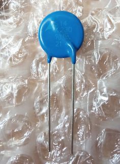
-
 Bild
Blauer Keramikkondensator
S14 K230 21 41
in „[V] Scheibenvaristoren TDK/Epcos S14K230“ · Markt · · Fotos
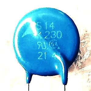
-
 Bild
Nahaufnahme einer Bauteilbeschriftung
BITRUN 230/1 K T 85
in „Siemens Waschmaschine WXT103E / 08 defekt, blinkt nur "Fehler"“ · Haus & Smart Home · · Fotos
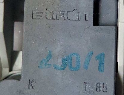
-
PDF
LED.pdf
LED, SMD, weiß, typ. 6530 K, 300 mA, typ. 110 lm, CRI 75, 120° LG Innotek 1000 / Gurt 500 322111 8541 4010 LEMWH51X75IZ00 LED, SMD, weiß, typ. 4503 K, 300 mA, typ. 110 lm, CRI 75, 120° LG Innotek 1000 / Gurt 500 322114 85410 4010
in „[V] Großer Posten SMD und THT LEDs günstig abzugeben“ · Markt ·
-
PDF
0401Koster58.pdf
diode is connected via a between 408 MHz and 457 MHz. 3.3 pF capacitor to the tapped resonant The 230 MHz oscillator Some thermal problems were observed circuit coil. The 0.25 pF feedback capac- For the sake of completion, a 230 at this high value of supply voltage. Both itor is created by two series
-
PDF
Koster58_VFO.pdf
diode is connected via a between 408 MHz and 457 MHz. 3.3 pF capacitor to the tapped resonant The 230 MHz oscillator Some thermal problems were observed circuit coil. The 0.25 pF feedback capac- For the sake of completion, a 230 at this high value of supply voltage. Both itor is created by two series
in „Clapp Oszillator mit oder ohne Bandpassfilter“ · HF, Funk und Felder ·
-
PDF
0401Koster58.pdf
diode is connected via a between 408 MHz and 457 MHz. 3.3 pF capacitor to the tapped resonant The 230 MHz oscillator Some thermal problems were observed circuit coil. The 0.25 pF feedback capac- For the sake of completion, a 230 at this high value of supply voltage. Both itor is created by two series
in „LC Oszillator beliebige LC Verhältnisse“ · HF, Funk und Felder ·
-
 Bild
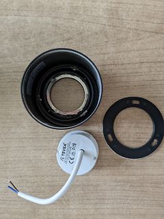
Einzelteile einer Leuchte oder eines Leuchtmittels
TEVEA 230V 50Hz 640lm 4000K 10W CE
in „LED Aufbau-Spot Metallgehäuse Schutzklasse 2“ · Haus & Smart Home · · Fotos