-
Datei
STM32F100RB_PWM_IO.c
CHN3, PB1: TIM3 CHN4 */ GPIO_Init(GPIOB, &GPIO_InitStructure); /* Initialize timer2 - output compare PWM */ // GPIO_PinRemapConfig(GPIO_FullRemap_TIM2, ENABLE); /* Remap Pins if necessary */ TIM_TimeBaseStructure.TIM_Period = 20000 - 1; /* PWM signal length 20 ms */ TIM_TimeBaseStructure.TIM_Prescaler
in „RC Servo Signale mit STM32 einlesen und ausgeben“ · Projekte & Code ·
-
PDF
_ATmega32.pdf
correct PWM mode, the compare units allow generation of PWM waveforms on the OC1x pins. Setting the COM1x1:0 bits to 2 will produce a non- inverted PWM and an inverted PWM output can be generated by setting the
in „Anschwingvorgang µC & Quarz“ · Mikrocontroller und Digitale Elektronik ·
-
PDF
ATMega16.pdf
PWM, 8-bit 0x00FF TOP TOP 6 0 1 1 0 Fast PWM, 9-bit 0x01FF TOP TOP 7 0 1 1 1 Fast PWM, 10-bit 0x03FF TOP TOP 8 1 0 0 0 PWM, Phase and Frequency CorrICR1 BOTTOM BOTTOM 9 1 0 0 1 PWM, Phase and Frequency
in „DCF auf INT0“ · Mikrocontroller und Digitale Elektronik ·
-
Datei
lueftersteuerung.bas
, 1 Lcd "Lueftersteuerung" Locate 2 , 1 Lcd "Peter K." 'Port Config Config Portb.3 = Output 'fan1 PWM Config Portd.7 = Output 'fan2 PWM Config Pind.2 = Input 'fan1 INT Portd.2 = 1 Config Pind.3 = Input 'fan2 INT Portd.3 = 1 Config Pinb.2 = Input 'taster Portb.2 = 1 Config Portb.1 = Output 'led Led Alias Portb.1 Config Portb.0 = Output 'summer Summer Alias Portb.0 'Timer, PWM und interupts Config Timer0 = Timer , Prescale = 1024 Enable Timer0 On Timer0 Isr_timer0 Config Timer1 = Pwm , Pwm = 8 , Compare A Pwm = Clear Down , Compare B Pwm = Clear Down , Prescale = 1 Compare1a
in „Bascom, AVR Lüftersteuerung, Falsche Drehzahl mit High-Side-PWM“ · Mikrocontroller und Digitale Elektronik ·
-
PDF
SDC7500_EN.pdf
Data sheet Voltage Mode PWM Controller SDC7500 General Description Features The SDC7500 incorporates all the functions Complete PWM power control circuitry required in the construction of a pulse-width Uncommitted outputs
in „Wechselrichter defekt“ · Analoge Elektronik und Schaltungstechnik ·
-
PDF
edison-module_HG_331189.pdf
26 GP45 GPIO 28 GP46 GPIO 30 GP47 GPIO 32 GP48 GPIO 34 GP49 GPIO 42 GP15 GPIO 48 GP14 GPIO 35 GP12_PWM0 PWM_0 GPIO, capable of PWM output 33 GP13_PWM1 PWM_1 GPIO, capable of PWM output 37 GP182_PWM2 PWM_2 GPIO, capable of PWM output 39 GP183_PWM3 PWM_3 GPIO, capable of PWM output 2 41 GP19 I2C_1_SCL
in „Intel Edison Breakout Board“ · Mikrocontroller und Digitale Elektronik ·
-
PDF
OD1238_REVERSIBLE-3135286.pdf
70,000 Hours (L10 at 40°C) Motor Restart, Polarity Protected, Electronically Protected Included Options PWM Speed Control Input Bearing System Ball Bearings Tachometer Output Dielectric Strength 500 VDC/min, <1mA Weight: 0.69 lbs Insulation Resistance ≥10M Ohm @ 500 VDC Rated Rated Speed Max Airflow Max.
-
PDF
MAX1630-MAX1635.pdf
Figure 2). above 25% of the full current limit in an active cycle, The two pulse-width modulation (PWM) controllers each allowing subsequent cycles to be skipped. Idle Mode consist of a Dual Mode™ feedback network and multi- transitions seamlessly to fixed-frequency PWM opera- plexer, a multi-input PWM
in „Steuerung für Elektrochrom-Spiegel (BMW 5er)“ · Mikrocontroller und Digitale Elektronik ·
-
PDF
zxld1366.pdf
R LX Switch ‘On’ resistance @ I = 1 A 0.5 0.75 ⍀ LX LX ILX(leak) LX switch leakage current 5 A D PWM(LF) Duty cycle range of PWM signal PWM frequency 0.001 1 applied to ADJ pin during low <300Hz frequency PWM dimming mode PWM amplitude = V REF Brightness control range Measured on ADJ pin 1000:1 DC
-
Datei
lauli1.asm
Mega8... ;Einfache Version mit Timer0-Überlauf-Interrupt ;Funktionsweise: ;Alle 8 Lampen glimmen per PWM ;Eine der 8 Lampen wird vom Glimmzustand bis zum Maximum hochgedimmt, ;dann wieder bis zum Glimmzustand heruntergedimmt. ;Danach geschieht das Gleiche mit der nächsten Lampe, ;immer hin und her. Die
in „Code von ganz besonderem Lauflicht vereinfachen“ · Mikrocontroller und Digitale Elektronik ·
-
Datei
lauli1.asm
Mega8... ;Einfache Version mit Timer0-Überlauf-Interrupt ;Funktionsweise: ;Alle 8 Lampen glimmen per PWM ;Eine der 8 Lampen wird vom Glimmzustand bis zum Maximum hochgedimmt, ;dann wieder bis zum Glimmzustand heruntergedimmt. ;Danach geschieht das Gleiche mit der nächsten Lampe, ;immer hin und her. Die
in „Frage zu Lauflicht“ · Mikrocontroller und Digitale Elektronik ·
-
Datei
main.c
########################################################################### { static unsigned char pwm_counter = 0; pwm_counter++; if(pwm_counter == 255) { pwm_counter = 0; } if(pwm_counter >= dmx_buffer[1]) { LED_R_OFF; } else { LED_R_ON; } if(pwm_counter >= dmx_buffer[2]) { LED_G_OFF; } else { LED_G_ON; } if(pwm_counter >= dmx_buffer[3]) { LED_B_OFF; } else { LED_B_ON; } if(dmx_lost<DMX_LOST_TIMEOUT) { dmx_lost++; } } //############################################################################ //Hauptprogramm
in „RGB Farbverlauf bei Radigs RGB Controller“ · Mikrocontroller und Digitale Elektronik ·
-
PDF
Attiny24a-44a-84a.pdf
correct PWM mode, the compare units allow generation of PWM wave- forms on the OC1x pins. Setting the COM1x[1:0] bits to two will produce a non-inverted PWM and an inverted PWM output can be generated by setting
in „Kann jemand über meine Inialisierung drüberfliegen?“ · Mikrocontroller und Digitale Elektronik ·
-
Datei
Fading_LED.txt
0x83; // non-inverted PWM on OC1A, 10 Bit Fast PWM TCCR1B = 0x08; TCCR1B &= ~0x7; // clear clk setting TCCR1B |= 3; // precaler 64 -> ~122 Hz PWM frequency for(tmp=30; tmp<=63; tmp++){ //original for(tmp=0; tmp<=63; tmp++){
in „PWM bei Mega8 und 2313“ · Mikrocontroller und Digitale Elektronik ·
-
PDF
STR751FR0T6.pdf
complementary T output) 83 G7 P2.08 / PWM2 I/O TT X X O2 X X Port 2.08 PWM: PWM2 output4) 84 G6 P2.07 / PWM2N I/O T X X O2 X X Port 2.07 PWM: PWM2 complementary T output) 85 F7 P2.06 / PWM3 I/O TT X X O2 X X Port 2.06 PWM: PWM3 output4) PWM
in „DAB Radio mit ARM Prozessor, HD44780 Display (BlueTinum BT-H1801)“ · Mikrocontroller und Digitale Elektronik ·
-
PDF
STK681-332-E.pdf
Derating Curve of Motor Current, I vs. STK681-332-E Operating Board Temperature, Tc O, 9 IO - Tc DC 8 PWM(V CC =24V) 7 PWM(V CC =33V) - 6 O t PWM(V CC =42V) e 5 r c 4 o o 3 M 2 1 0 0 10 20 30 40 50 60 70 80 90 100 110 OperatingSubstrateTemperature,Tc-°C ITF02711 (The maximum PWM frequency is 50kHz.) The PWM frequencies in the above graph indicate the ENABLE signal. The same PWM I derating curves as those shown above will be obtained when the internal PWM frequency of the O STK681-332-E is used. Increasing
in „Thermische Berechnung bei H-Brückentreiber“ · Mikrocontroller und Digitale Elektronik ·
-
PDF
SG6105A.pdf
S G 1 0 July 2009 A — P w SG6105A e r Power Supply Supervisor + Regulator + PWM u p p y Features Description S p PC Half-Bridge (or 494) Power Supply Supervisor +A controller is designed for switching-moee two 431 + PWM power supplies for desktop PCs. It provides allvthe functions
-
PDF
Artikel_zum_Magnet-Schweberegler.pdf
= 32 , Reference = Off If Y > 255 Then Y = 255 ‘ AD-Wandler starten If Y < 0 Then Y = 0 Start Adc Pwm0a = Int(y) Config Timer0 = Pwm , Presca- Loop le = 1 , Compare A Pwm = 7-8/2008 - elektor 13 praxis mikrocontroller a Display anzeigt. Nach dem Anlegen der Betriebsspannung beziehungsweise nach einem
in „Schwebender Globus, wie funktioniert das? Selbstbauen?“ · Mikrocontroller und Digitale Elektronik ·
-
Datei
spi_slave.cpp
); volatile uint8_t& pwm_val = *(regs+ADDR_PWM_VAL); volatile uint8_t& battery_val = *(regs+ADDR_BATTERY_VAL); volatile int16_t& rpm_w = *((int16_t*)(regs+ADDR_RPM_W_L)); volatile uint16_t& kp = *((uint16_t*)(regs+ADDR_KP_L
in „SPI Attiny44“ · Mikrocontroller und Digitale Elektronik ·
-
Datei
LCD_PWM_ATtiny2313.c
include <lcd-routines.h> #include <util/delay.h> #include <stdlib.h> void timer_init() { //TIMER 4 PWM Init TCCR0A |= (1<<COM0A1) | (1<<WGM00); // PWM 0A TCCR1A |= (1<<COM1A1) | (1<<COM1B1) | (1<<WGM10); // PWM 1A,1B TCCR0B |= (1<<CS00);// kein Vorteiler an T0 für max. Teiler CSx2 setzen TCCR1B |= (1
in „ATtiny2313 / LCD2x16 / String Ausgabe fehlerhaft“ · Mikrocontroller und Digitale Elektronik ·
-
PDF
e8_wiring_diagram.pdf
RELAY PIN LAYOUT & SCHEMATIC FUEL PUMP RELAY [GY] 85 IGN SWITCHED +12V SUPPLY FROM IGNITION SWITCH 86 PWM OUT#1 [ V / W ] PWM OUT#1 18 [ P / B ] 87 PWM OUT#2 PWM OUT#2 1 87 N/C [ L / G ] PWM OUT#3 [O] +12V SUPPLY TO PUMP PWM OUT#3 23 30 P+ CONNECT TO PUMP + J9 : IDLE SPEED MOTOR SUITS BOSCH RELAY P/N:0
in „Vollprogrammierbare Zündanlage für 1Zylinder 2 und 4 Takt Motoren“ · Mikrocontroller und Digitale Elektronik ·
-
PDF
Manual_netX_Program_Reference_Guide_Rev02_GB.pdf
PWM 0 Period 0x00162a64 PWM1_TP PWM 1 Period 0x00162968 PWM0_TU PWM 0 Channel U Low Phase Width 0x00162a68 PWM1_TU PWM 1 Channel U Low Phase Width 0x0016296c PWM0_TV PWM 0 Channel V Low Phase Width 0x00162a6c PWM1_TV PWM 1 Channel V Low Phase Width 0x00162970 PWM0_TW PWM 0 Channel W Low Phase Width 0x00162a70 PWM1_TW PWM 1 Channel W Low Phase Width 0x00162974 PWM0_TD PWM 0 Dead Time Counter Preload 0x00162a74
in „netX500 mit ARM-Kern“ · Mikrocontroller und Digitale Elektronik ·
-
PDF
Zigbee_Lightstrip-Controller.pdf
verwendet; das Verhältnis der Dauer An zu Aus bestimmt die Helligkeit (sogenannte Pulsweitenmodulation, PWM). Genau dies für die Ansteuerung benötigte PWM-Signal liefern die Module aus den Tradfri-Leuchtmitteln. Neben dem Stepdown-Konverter und dem Zigbee-Modul bedarf es daher nur noch eines geeigneten MosFETs
in „Dimmbare 12V~ LED-Strahler mit PWM dimmen - welche Gleichspannung?“ · Analoge Elektronik und Schaltungstechnik ·
-
PDF
AT90CAN128.pdf
correct PWM mode, the compare units allow generation of PWM wave- forms on the OCnx pins. Setting the COMnx1:0 bits to two will produce a non-inverted PWM and an inverted PWM output can be generated by setting
in „Umrechnen von analog to digital“ · Mikrocontroller und Digitale Elektronik ·
-
PDF
RCDN9.pdf
Physical Characteristics 2.1.1 TAS5558 Pin Assignments TAS5558 (MAIN : IC23) DCA Package (Top View) PWM_HPM_L 1 56 PWM_P_6 PWM_HPP_L 2 55 PWM_M_6 PWM_HPM_R 3 54 PWM_P_5 PWM_HPP_R 4 53 PWM_M_5 AVSS 5 52 VR_PWM PLL_FLTM 6 51 AVSS_PWM PLL_FLTP 7 50 AVDD_PWM VR_ANA 8 49 PWM_P_8 AVDD 9 48 PWM_M_8 ASEL_EMO2 10 47 PWM_P_7 MCLK 11 46 PWM_M_7 OSCRES 12 45 PWM_P_4 DVSS2_CORE 13 44 PWM_M_4 DVDD2_CORE 14 43 PWM_P_3 EMO1 15 TAS5558 42 PWM_M_3 RESET 16 41 PWM_P_2 HP_SEL 17 40 PWM_M_2 PDN 18 39 PWM_P_1 MUTE 19 38 PWM_M_1
in „Hifi Kompaktanlage mit Bluetooth Sender ausstatten“ · Analoge Elektronik und Schaltungstechnik ·
-
 Bild
Bild
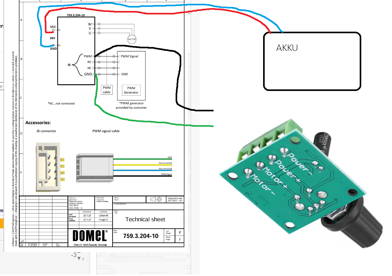
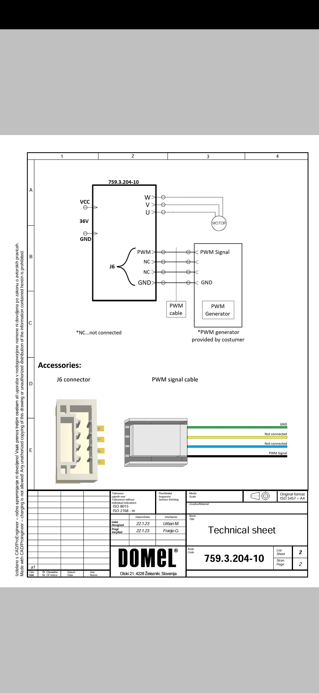
Schaltplan mit Foto einer Leiterplatte und Verkabelung
VCC, W, V, U, 36V, GND, MOTOR, PWM, J6, PWM Signal, NC, GND, PWM Generator, *PWM generator provided by costumer, Accessories, J6 connector, PWM signal cable, GND, Not connected, PWM Signal, DOMEL, 759.3.204-10, Technical sheet, AKKU
in „Brushles motor steuerung pwn TX RX GND“ · Analoge Elektronik und Schaltungstechnik · · Fotos
-
PDF
STR-W6253D_PWMswitschRegulator.pdf
STR-W6253D 60W-Universal Input/90W-230 Vac Input PWM Switching Regulators Features and Benefits Description ▪ Overcurrent protection (OCP) with ac input voltage The STR-W6200D series are current-mode PWM ICs that compensation function; no additional peripheral
in „suche Diode aus Schaltnetzteil“ · Analoge Elektronik und Schaltungstechnik ·
-
PDF
STR-W6253D_PWMswitschRegulator.pdf
STR-W6253D 60W-Universal Input/90W-230 Vac Input PWM Switching Regulators Features and Benefits Description ▪ Overcurrent protection (OCP) with ac input voltage The STR-W6200D series are current-mode PWM ICs that compensation function; no additional peripheral
in „Reparatur Audio-Schaltnetzteil“ · Analoge Elektronik und Schaltungstechnik ·
-
 Bild
Bild
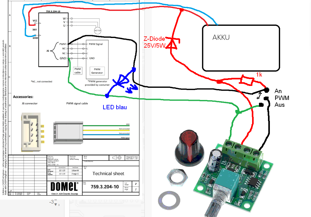
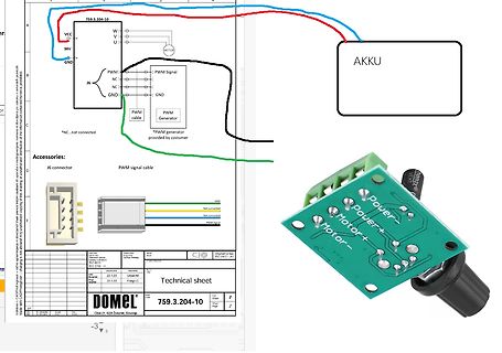
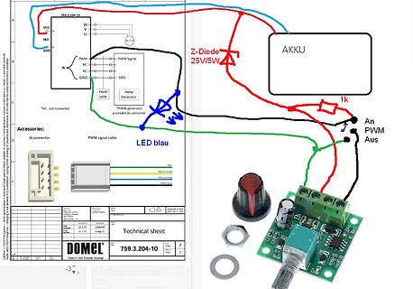
Kombination aus Schaltplan, Bauteilen und freier Verdrahtung
VCC, 36V, GND, MOTOR, PWM Signal, J6, NC, GND, PWM generator, PWM cable, Z-Diode 25V/5W, AKKU, 1k, An PWM Aus, LED blau, Accessories: J6 connector, PWM signal cable, GND, PWM signal, Technical sheet, DOMEL, 759.3.204-10
in „Brushles motor steuerung pwn TX RX GND“ · Analoge Elektronik und Schaltungstechnik · · Fotos
-
 Bild
Bild
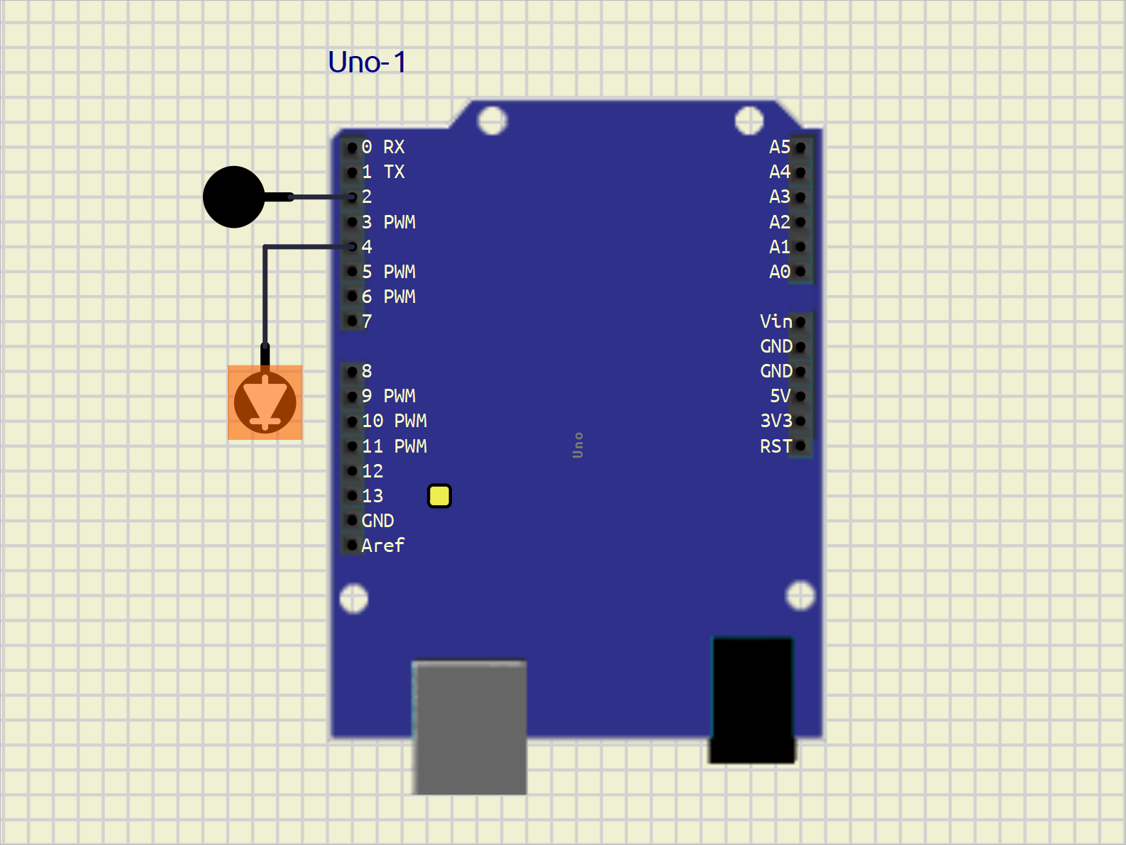
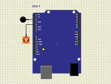
Grafische Darstellung eines Arduino Uno mit LED-Anschluss
Uno-1 0 RX 1 TX 2 3 PWM 4 5 PWM 6 PWM 7 8 9 PWM 10 PWM 11 PWM 12 13 GND Aref A5 A4 A3 A2 A1 A0 Vin GND 5V 3V3 RST Uno
in „Simulation Arduino Uno-9 in SimulIDE 1.1.0-SR2 at Rev 260312“ · Mikrocontroller und Digitale Elektronik · · Screenshots
-
 Bild
Bild
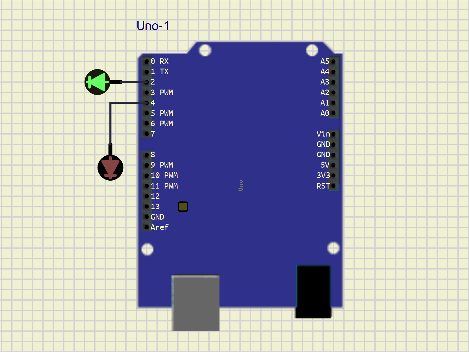
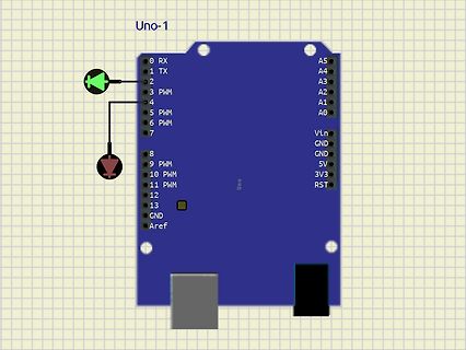
Grafische Darstellung eines Arduino Uno mit LEDs
Uno-1 0 RX 1 TX 2 3 PWM 4 5 PWM 6 PWM 7 8 9 PWM 10 PWM 11 PWM 12 13 GND Aref A5 A4 A3 A2 A1 A0 Vin GND 5V 3V3 RST Uno
in „Simulation Arduino Uno-9 in SimulIDE 1.1.0-SR2 at Rev 260312“ · Mikrocontroller und Digitale Elektronik · · Screenshots
-
Datei
bus124-attiny13.c
BIT_TIME (F_CPU / BIT_CLK / PRESCALER) #include <util/delay.h> #define DATA_SIZE 3 // 2 Byte #define PWM SBIT( PORTB, PB3 ) //PC4 #define PWM_DDR SBIT( DDRB, PB3 ) //PC4 #define DATA SBIT( PORTB, PB0 ) //PB3 #define DATA_DDR SBIT( DDRB, PB0 ) //PB3 #define DATA_PIN SBIT( PINB, PB0 ) //PB3 /************
in „Möglichst Resourcenschonend programmieren“ · Mikrocontroller und Digitale Elektronik ·
-
Datei
PWM_PA0_Uvergleich_5ms_rs232.asm
;ausgangsspannungsregelung nach stepdown ;pwm an atmega16 für 2 khz ;bei 4mhz taktfrequenz ;mit timer0 im fast pwm mode, 8 bit aufloesung ;pwm-signal liegt auf pb3 oc0 ;adc takt mittels rcall ;rs232 ausgabe+bcd wandlung mittels rcall ;werner/16.2.12
in „Hilfe Ladereglung Atmega16 Assembler“ · Mikrocontroller und Digitale Elektronik ·
-
PDF
arduino-leonardo-schematic_3b.pdf
RESET (PCINT5/OC1A/#OC4B/ADC12)PB5 29 IO9* IO9* 9# #PWM 16bit +A10 +PWM COMPL IO10 C 2 RESET C (ADC11/PCINT4)PB4 28 IO8 (ADC11/PCINT4)PB4 28 IO8 IO8 8 +A9 N (PD0/MISO/PCINT3)PB3 11 MISO (PD0/MISO/PCINT3)PB3 11 MISO MISO G XTAL2 16 XTAL2 (PDI/MOSI/PCINT2)
in „externe Speisung eines Arduino Leonardo“ · Mikrocontroller und Digitale Elektronik ·
-
 Bild
Bild
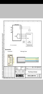
Technisches Datenblatt eines Anschlusses und Steckverbinders
759.3.204-10 VCC 36V GND J6 PWM NC NC GND W U MOTOR PWM Signal PWM cable PWM Generator provided by costumer Accessories: J6 connector PWM signal cable GND Not connected Not connected PWM Signal DOMEL Otoki 41. 4228 Žeželj, Slovenija
in „Brushles motor steuerung pwn TX RX GND“ · Analoge Elektronik und Schaltungstechnik · · Screenshots
-
Datei
ledgame.c
- 1) - ledstate[ledno], pwm_cb, arg); } else { /* LED is off, turn on */ if (ledstate[ledno] == 0) goto retrigger; PORTB &= ~(1 << ledno); timeout(ledstate[ledno], pwm_cb, arg); } return; retrigger: timeout(PWMPERIOD - 1, pwm_cb, arg); } int main(void) { union timeoutarg u; uint16_t ticks = 0; ioinit(); /* start the LED PWMs */ for (u.i = 0; u.i < NLEDS; u.i++) { timeout(1, pwm_cb, u); if (ledstate[u.i] >= PWMPERIOD -1) PORTB &= ~(1 << u.i); } for (;;) { if (intbits.tmr2_int) { intbits.tmr2_int = 0; timertick(); /* * Just
in „PWM mit Timer0“ · Mikrocontroller und Digitale Elektronik ·
-
Datei
Motor.c
PWM) (Aus Tabelle 15-5) TCCR1B |= ((0<<CS12) | (0<<CS11) | (1<<CS10)); //Kein Teiler (Aus Tabelle 15-6) TCCR1B |= ((1<<WGM13) | (1<<WGM12)); //Mode 3 (Fast PWM) (Aus Tabelle 15-5) ICR1=1024; //Top-Wert
in „zwei if-Anweisungeg funktionieren nicht zusammen“ · Mikrocontroller und Digitale Elektronik ·
-
PDF
mini_edison_breakout_hvm_8_26.pdf
_TX GP165 5,8 5,8 GP46 30 29 GP135 4,5,8 5,8 GP47 32 31 5,8 GP48 RCVR_MODE 5,8 5,8 GP49 34 33 GP13_PWM1 5,8 5,8 RESETOUT# 36 35 GP12_PWM0 5,8 38 37 GP182_PWM2 5,8 40 39 GP183_PWM3 5,8 5,8 GP15 42 41 I2C1_SCL GP19 5,8 5,8 GP84 SD_CLK_FB 44 43 I2C1_SDA GP20 5,8 5,8 GP131 UART1_TX 46 45 I2C6_SCL AUDIOCODEC_INT
in „Intel Edison Breakout Board“ · Mikrocontroller und Digitale Elektronik ·
-
Datei
main.c
########################################################################### { static unsigned char pwm_counter = 0; pwm_counter++; if(pwm_counter == 255) { pwm_counter = 0; } if(pwm_counter >= dmx_buffer[1]) { LED_R_OFF; } else { LED_R_ON; } if(pwm_counter >= dmx_buffer[2]) { LED_G_OFF; } else { LED_G_ON; } if(pwm_counter >= dmx_buffer[3]) { LED_B_OFF; } else { LED_B_ON; } if(dmx_lost<DMX_LOST_TIMEOUT) { dmx_lost++; } } //############################################################################ //Hauptprogramm
in „RGB Farbverlauf bei Radigs RGB Controller“ · Mikrocontroller und Digitale Elektronik ·
-
Datei
main.c
Modus // Umschalter an PC0/PC1 - 1/0 Stufe 1 - 0/0 Stufe 2 - 0/1 Stufe 3 // Ausgang PB1 - Luefter PWM Ausgang // Ausgang PD5 - Rechtslauf // Ausgang PD6 - Linkslauf // Timer 1 PWM einstellen void timer1_init(void) { // OC1A auf Ausgang DDRB = (1<<PB1); // Was die einzelnen Einstellungen genau bedeuten
in „Inventer Lüfter Ansteuerung“ · Analoge Elektronik und Schaltungstechnik ·
-
Datei
LCD_0inch96.py
= 160 self.cs = Pin(9,Pin.OUT) self.rst = Pin(12,Pin.OUT) # self.bl = Pin(13,Pin.OUT) self.cs(1) # pwm = PWM(Pin(13))#BL # pwm.freq(1000) self.spi = SPI(1) self.spi = SPI(1,1000_000) self.spi = SPI(1,10000_000,polarity=0, phase=0,sck=Pin(10),mosi=Pin(11),miso=None) self.dc = Pin(8,Pin.OUT) self.dc(1)
in „Circuitpython und Waveshare PiPico2 LCD0 nch96“ · Mikrocontroller und Digitale Elektronik ·
-
PDF
200959141322092079_SD600Apdf.pdf
可采用驱动/吸收电流两种工作 模式。该芯片可广泛应用于 LED 灯具。 1.2 特点 数据传输速率高达 12Mbit/S 低功耗 CMOS 工艺 无需晶体,少量外围电路 2048 颗芯片级联的能力 三路 PWM 调光控制器 (256 级灰度) 24 位真彩色(8R+8G+8B) 可外接驱动 低泄漏电流 高达 24mA 驱动电流的集开门输出(带缓冲) I/O ESD 保护(2.5 kV HBM) SSOP10 封装 1.3 应用领域 LED 灯具 2 YDSCO 科技创新生活 PWM 产生器 性能参数 2.1 系统功能图 3 YDSCO 科技创新生活 2.2 引脚图 2.3 引脚定义 引脚名称 引脚标号
in „"intelligent" LED Leiste“ · Mikrocontroller und Digitale Elektronik ·
-
Datei
BLDC.c
{ U = 0; W = 1; } if(Hall1 == 1 && Hall2 == 0 && Hall3 == 1) { U = 0; V = 1; } } volatile uint8_t pwm_soll; // gewünschter Dimmerwert 0..100 volatile uint8_t PWMCounter = 0; //Laufvariable, gibt die Anzahl an Schritten wieder, hier 0-100 int main( void ) { initial(); ADC_Init(); uint16_t pwmfs; while(1) { //Soft-PWM für alle Enalbe Eingänge des L298N, dient der pwmfs = ADC_Read(5); pwm_soll = pwmfs/10; if (pwm_soll < 4) { pwm_soll = 4; } if (pwm_soll > 100) { pwm_soll = 100; } if (pwm_soll == PWMCounter) { ENA1
in „BLDC dreht CCW schneller als CW?“ · Mikrocontroller und Digitale Elektronik ·
-
PDF
85272_lc444_schaltplan.pdf
+U-IN D1 1 0 2 0 3 0 4 0 LL4148 5 R R 1 R 1 R 1 R 1 D2 R LL4148 D3 R7 2K7 T1 R8 C1 LL4148 6 R PWM1 2K7 T2 D4 R BD136 100p D5 BC848C R10 SMD LL4148 R11 2K7 T3 LL4148 9 x C2 D6 R R PWM2 2K7 T4 BD136 100p BC848C SMD LL4148 D7 R13 2K7 T5 2 R14 C3 LL4148 1 R PWM3 2K7 T6 BD136 D8 R BC848C 100p LL4148
in „LED CUBE selberbauen“ · Mikrocontroller und Digitale Elektronik ·
-
 Bild
Bild
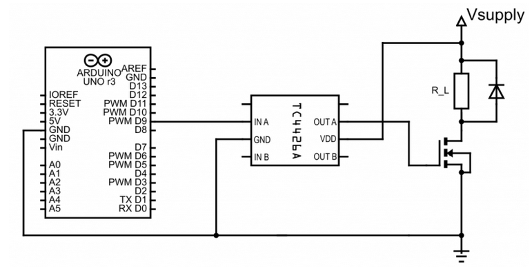
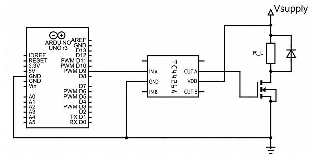
Schaltplan mit Arduino Uno und TC4226A Treiber
ARDUINO UNO r3, AREF, GND, D13, D12, PWM D11, PWM D10, PWM D9, D8, D7, PWM D6, PWM D5, D4, PWM D3, D2, TX D1, RX D0, A0, A1, A2, A3, A4, A5, Vin, GND, 5V, 3.3V, IOREF, RESET, TC4226A, IN A, GND, IN B, OUT A, VDD, OUT B, R_L, Vsupply
in „IGBT Modul SKM150GAL12T4 brennt durch“ · Analoge Elektronik und Schaltungstechnik · · Schaltpläne
-
PDF
BT-WiFi-52rf5541.pdf
account. When the resolution for the application is decided, it’s advised not to change it again. The PWM address is show as below; the basic address is 0XA00 in external RAM space. ADDRESS PWM_CTRL PWM_DCLSB PWM_DCMSB PWM_RESOLUTION PWM0 0XA00 0XA01 0XA02 0XA03 PWM1 0XA04 0XA05 0XA06 0XA07 PWM2 0XA08 0XA09
in „JDY-40 ein neuer Geniestreich aus China?“ · Mikrocontroller und Digitale Elektronik ·
-
 Bild
Bild
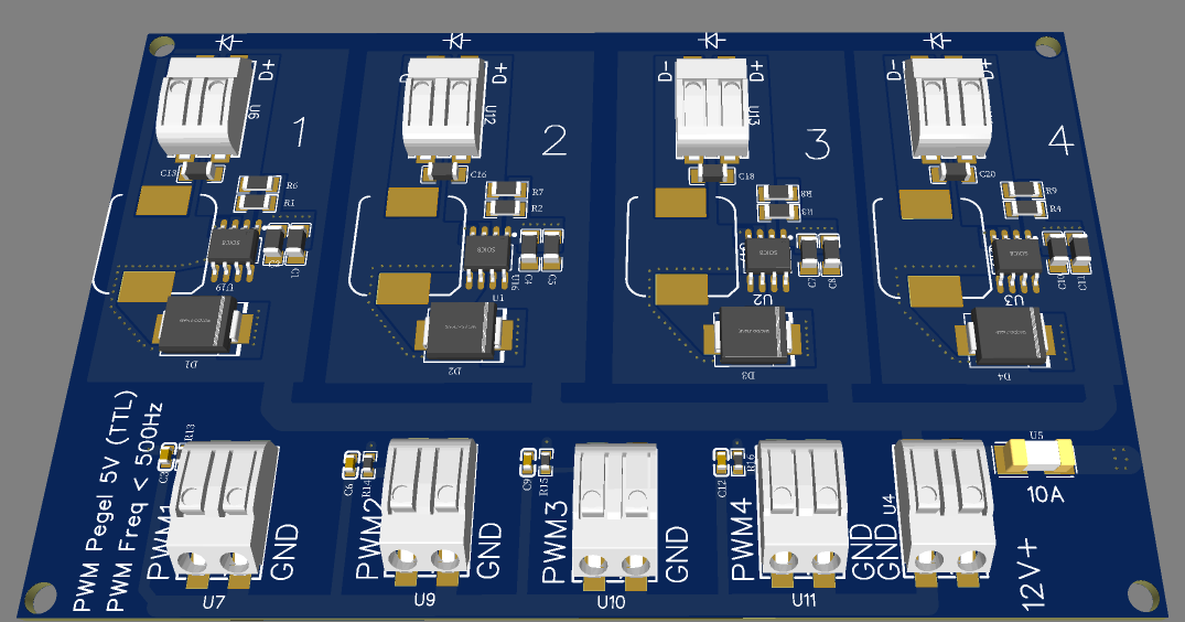
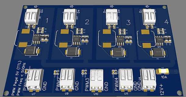
3D-CAD-Modell eines Leiterplatten-Layouts
D+ U5 1 R6 R1 U19 C16 U12 2 D- U13 C18 3 D+ U14 C20 R9 R4 U3 4 U2 C19 U2 D4 D3 U18 U19 PWM Pegel 5V (TTL) PWM Freq < 500Hz PWM1 U7 GND PWM2 U9 GND PWM3 U10 GND PWM4 U11 GND U4 12V+ 10A
in „LED Ansteuerung für Lazertag Projekt“ · Mikrocontroller und Digitale Elektronik · · Layouts
-
PDF
PIC16F1939.pdf
. TABLE 23-1: PWM RESOURCES Device Name ECCP1 ECCP2 ECCP3 CCP4 CCP5 Enhanced PWM Enhanced PWM Enhanced PWM PIC16F/LF1933/36/38 Standard PWM Standard PWM Full-Bridge Half-Bridge Half-Bridge Enhanced PWM Enhanced PWM Enhanced
in „MPLAB delay und xtalfreq richtig benutzen“ · Mikrocontroller und Digitale Elektronik ·
-
Datei
rgb.asm
.include "tn13def.inc" .def S = r3 ;Status-Byte .def temp = r18 .def pwm = r22 ;Zähler .def rot = r23 ;6bit RGB-Werte .def gruen = r24 .def blau = r25 .def rt = r4 ;8bit RGB-Werte .def gn = r5 .def bl = r6 .equ ledport = PORTB .equ pRed = PORTB1 .equ pGreen = PORTB0 .equ
in „[ASM] RGB Tabelle komischer Wert“ · Mikrocontroller und Digitale Elektronik ·
-
Datei
attiny26_PWM_2.bas
drann hängt $crystal = 16000000 'Hab gerade nur nen 16 Mhz Quarz da Dim A As Byte Config Timer1 = Pwm , Pwm = 8 , Compare A Pwm = Clear Down , Compare B Pwm = Clear Up , Prescale = 1 Do Gosub Pwm Loop Pwm: For A = 1 To 255 Ocr1c = 255 'Comparewert Ocr1a = A 'Ausgabe 1a Ocr1b = A 'Ausgabe 1b Waitms 10
in „Tiny26 PWM Problem mit Setzen des Compareregisters ?“ · Mikrocontroller und Digitale Elektronik ·