-
PDF
WM8978.pdf
ADC DigitaADCVU ADCVOLR 0FF Vol 18 12 EQ1 – low shelEQ3DMODE 0 EQ1C EQ1G 12C 19 13 EQ2 – peak 1 EQ2BW 0 EQ2C EQ2G 02C 20 14 EQ3 – peak 2 EQ3BW 0 EQ3C EQ3G 02C 21 15 EQ4 – peak 3 EQ4BW 0 EQ4C EQ4G 02C 22 16 EQ5 – high shelf 0 0 EQ5C EQ5G 02C 24 18 DAC Limiter 1 LIMEN
in „GSM + GPS Modul von Pollin“ · Mikrocontroller und Digitale Elektronik ·
-
PDF
BME280_Datasheet.pdf
4.2 ×4 / ×1 2.1 1.2 0.8 0.5 0.3 7.1 ×8 / ×1 1.6 1.0 0.6 0.4 0.2 12.8 ×16 / ×2 1.3 0.8 0.5 0.4 0.2 24.9 Table 13: Temperature dependence of pressure noise RMS noise at different temperatures Temperature Typical change in noise compared to 25 °C -10 °C +25 % 25 °C ±0 % 75 °C -5 % BST-BME280-DS001-10 |
in „PIC18F, Sensor auslesen I2C“ · Mikrocontroller und Digitale Elektronik ·
-
PDF
OM6206U_Z.pdf
− V5 3 2 V 4 V LCD − V LCD 0 1 2 3 4 5 6 7 8... ... 64 0 1 2 3 4 5 6 7 8... ... 64 MGT860 Vstate1) = C1(t) to R0(t). V (t) = C1(t) to R1(t). state2 Fig.2 Typical LCD driver waveforms. 2001 Nov 14 7 Philips Semiconductors Product specification 65 × 102 pixels
in „Display VG-G090651 von Pollin“ · Mikrocontroller und Digitale Elektronik ·
-
PDF
Labornetzteil.pdf
Last (2x 12V; jeweils 2,4A; interne Wärmemenge: 85W) 60 50 40 ] [ t 30 e e 20 Kühlkörper rechts [°C] T K51U Kühlkörper links [°C] Temp. Dioden links [°C] 10 0 0 5 10 15 20 25 30 35 Zeit [min] 1.2. Geräteverdrahtung 1.3. Elektrische Sicherheit beim Gerätebau Achtung: Aufgrund der in den nachfolgend
in „Präzisions Labornetzteil 2x30V 3A, Eigenbau“ · Analoge Elektronik und Schaltungstechnik ·
-
Datei
akkuboost2IO.h
USER_BIT2)) // minimal and maximal capacity of the batteries in all slots /* EEPROM: Offset Bytes 0 64 8 user characters for the display 64 64 capacity min for 32 battery slots 128 64 capacity max for 32 battery slots 192 64 max power dissipation for 32 battery slots 256 704 battery_data array */ #define
in „Suche Hilfe beim Compilieren von fertigem C-Code“ · Mikrocontroller und Digitale Elektronik ·
-
 Bild
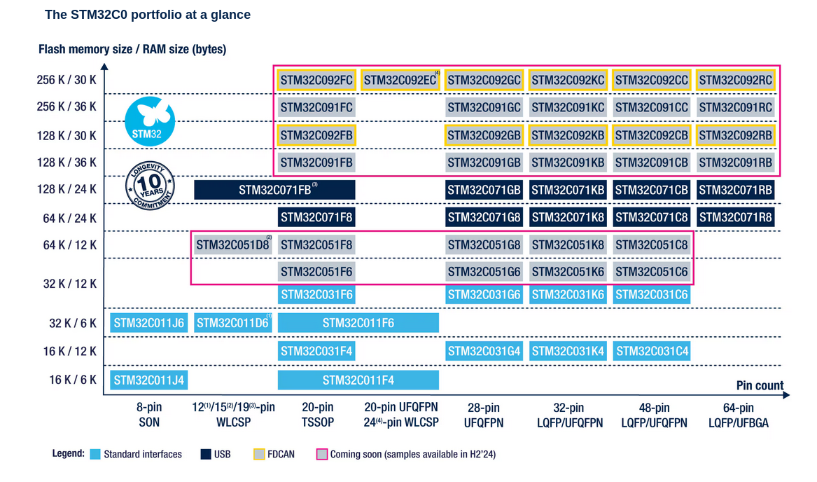
Übersicht der STM32C0 Mikrocontroller-Portfolio-Varianten
The STM32C0 portfolio at a glance Flash memory size / RAM size (bytes) 256 K / 30 K 128 K / 30 K 128 K / 36 K 128 K / 24 K 64 K / 24 K 64 K / 12 K 32 K / 12 K 32 K / 6 K 16 K / 12 K 16 K / 6 K STM32C092FC, STM32C092EC, STM32C092GC, STM32C092KC, STM32C092CC, STM32C092RC, STM32C091FC, STM32C091GC, STM32C091KC, STM32C091CC, STM32C091RC, STM32C092FB, STM32C092GB, STM32C092KB, STM32C092CB, STM32C092RB, STM32C091FB, STM32C091GB
in „Halbleiter-Allerlei: Zenerdioden, Mikrocontroller und mehr“ · Mikrocontroller und Digitale Elektronik · · Screenshots
-
PDF
BZX55__VISHAY-2013.pdf
< 0.1 < 2 15 < 55 < 220 0.03 0.11 BZX55C22 20.8 22 23.3 5 1 < 0.1 < 2 16 < 55 < 220 0.04 0.12 BZX55C24 22.8 24 25.6 5 1 < 0.1 < 2 18 < 80 < 220 0.04 0.12 BZX55C27 25.1 27 28.9 5 1 < 0.1 < 2 20 < 80 < 220 0.04 0.12 BZX55C30 28 30 32 5 1 < 0.1 < 2 22 < 80 < 220 0.04 0.12 BZX55C33 31 33 35 5 1 < 0.1 < 2 24 < 80 < 220 0.04 0.12 BZX55C36 34 36 38 5 1 < 0.1 < 2 27 < 80 < 220 0.04 0.12 BZX55C39 37 39 41 2.5 0.5 < 0.1 < 5 30 < 90 < 500 0.04 0.12 BZX55C43 40 43 46 2.5 0.5 < 0.1 <
in „Z-Diode macht nicht was ich denke“ · Analoge Elektronik und Schaltungstechnik ·
-
PDF
armStoneA8_Hardware_V110_eng.pdf
Flash (optional 1 GByte) CPU: Samsung S5PV210 800MHz CPU (optional 1GHz) Operating temperature: 0°C...+70°C (optional -20…+85°C) 3 Block diagram Digital to LVDS LVDS 18 bit (JAE FI-S25S) 4 wire resistive touch (Hirose DF13A-4P) I2C If for capacitive touch (Hirose DF13A-6P) microSD push-push 2x 64M
in „Handydummy (Attrappe)mit richtigem Display 10Zoll - u.a.Motorola Xoom“ · Mikrocontroller und Digitale Elektronik ·
-
PDF
253499-da-01-en-AKKU_BLEI_12V_12_AH.pdf
2.2 177 34 60 66 0.8 50 G188151 Vmax. Vmin. and humidity Height (mm) Continuous load Trickle/Float ˚C max. ˚C min. Length (mm) max. LC-R123R4PG 12 3.4 134 67 60 66 1.2 52 G191053 charge LC-R124R5P 12 4.5 70 97 102 108 1.5 54 – mA(max.) % max. % min. Width (mm) max. mA(av.) LC-R127R2PG *2 12 7.2 151 64.5
in „[v] Zyklenfeste 12v 144Wh Akkus Panasonic 12 V 12 Ah LC-RA1212PG1 Blei-Vlies (AGM)“ · Markt ·
-
Datei
akkuload.asm
verwendbar .EQU bLcd0 = 0 ; Zeile 1 der LCD ist frei verwendbar ; ; ; Berechnete Konstanten ; .EQU cTC1Prsc = 8 ; TC1 Vorteiler-Wert .EQU cTC1Div = fClock / cTC1Prsc / 64 ; 64 Interrupts pro Sekunde .EQU cTC1CompB = 50 ; Timer-Wert für den Start der ADC-Umwandlung .EQU cStartAdc = (1<<ADEN)|(1<<ADPS2
in „Asssembleprogramm für Mega16 auf Mega8535 anpassen, Sprungweite "call" und "jmp"“ · Mikrocontroller und Digitale Elektronik ·
-
PDF
sct2210.pdf
DD= 5V ) V DD = 5V a 80 V OUT= 2V a 80 V OUT= 2V m 60 16 bits active m 60 16 bits active ( Ta = 85 C -▲-▲-▲- ( Ta = 85 C -▲-▲-▲- U 40 Ta = 25 C ------ U 40 Ta = 25 C ------ O 20 SSOP24-1.0: Rth = 68℃/W O 20 SDIP24: Rth = 60℃/W I I 0 0 0 10 20 30 40 50 60 70 80 90 100 0 10 20 30 40 50 60 70 80 90 100
in „[V] 50 x 16bit LED-Konstantstrom-Schieberegister, SCT2210CSTG“ · Markt ·
-
PDF
UBR2.pdf
-X hnge ie -ChangeVe D !er DF !r P OW P OW uyN uN tb tb lc UBR2 lk ww C o ww C om w.doc ac.c wdoc ack. u-r u-t R UBR 2 o a Dimensions (mm)∅ 36 x 21 t o n Voltage (V)2–230 a l Speed (rpm) 50 Hz00 60 Hz 600 Pole number12 Running torque (cNm) 50 Hz0.64 60 Hz 61 Power output
in „Widerstandswert nicht eindeutig“ · Analoge Elektronik und Schaltungstechnik ·
-
PDF
calling_conventions_for_different_C_compilers_and_operating_systems__fog.pdf
tests indicate that these registers are saved correctly during task switches and thread switches in 64-bit mode, even in an early beta version of x64 Windows. The Microsoft C++ compiler version 14.0 never uses these registers in 64-bit mode, and doesn't support long double precision. The Intel C++ compiler
in „C und C++ kompatibilität“ · Mikrocontroller und Digitale Elektronik ·
-
Datei
t6963c.h
/* ---------------------------------------------------------- * Program to control a T6963C-based 240x64 pixel LCD display * * * * Written by John P. Beale May 3-4, 1997 beale@best.com * * Converted by Nico Sachs Feb. 2006 for AVR-GCC * * Based on information from Steve Lawther, * "Writing
in „T6963C an Mega16 - Einige Pixel verirren sich ^^“ · Mikrocontroller und Digitale Elektronik ·
-
PDF
DE200610__1_.pdf
1 4 R14, R16 = 47 k C R C C3 R15 = 220 Ω I 8 R17, R18 = 100 Ω R 1 R15 44 ) 2 2 R R14 44 E R23, R24 = 1M R C2 99 T P1 = 10 k Trimmpotentiometer R R7 2 11-R I Kondensatoren: 1 R9 C C1, C2 = 27 p P1 C3, C10 = 1 µ/63 V, 5 mm
in „ekg schaltung aus heft 10/2006“ · Analoge Elektronik und Schaltungstechnik ·
-
PDF
USR-K6-user-manual-V1.0.0.pdf
67 basic parameters. Setting For better Settings, here are some examples: sending: FF 56 05 D8 B0 4C 46 35 CA 61 64 6D 69 6E 00 61 64 6D 69 6E 00 95 63 03 00 00 00 50 00 00 07 00 A8 C0 01 00 A8 C0 00 FF FF FF 55 53 52 2D 4B 32 00 00 00 00 00 00 00 00 00 00 61 64 6D 69 6E 00 61 64 6D 69 6E 00 00 01 00
in „[V] 3St.(neu) Ethernet- SeriellModule USR-K6 (alle für 20€)“ · Markt ·
-
PDF
man_gcc.pdf
, c64x, c64x+, c67x, c67x+, c674x. -mbig-endian Generate code for a big-endian target. -mlittle-endian Generate code for a little-endian target. This is the default. -msim Choose startup files and linker
in „avr-g++: external linkage von const/PROGMEM Symbol.“ · Mikrocontroller und Digitale Elektronik ·
-
Datei
Build-Listing.txt
: .word IRQ_Routine /* defined in main.c */ 59 0038 00000000 FIQ_Addr: .word FIQ_Routine /* defined in main.c */ 60 003c 00000000 .word 0 /* rounds the vectors and ISR addresses to 64 bytes total */ 61 62 # Reset Handler 63 64 Reset_Handler
in „GNUARM-Linker ERROR wegen hardware FP“ · Mikrocontroller und Digitale Elektronik ·
-
PDF
lcd4busy16new.lib.pdf
;Const _lcd_e = 1 ;Const _lcd_rw = 2 ;Const _lcd_rs = 3 ;40ms warten nach Power on reset Ldi R30, 64 Ldi R31, 156 Rcall _lcd_delay ; 40 ms warten ;Displayinitialisierung: [_init_lcd] _init_lcd: clr R24 ;alle pins displayport low setzen * Out _lcdport , R24 ser r24 ;port als output setzen * Out _lcdddr , R24 Ldi R30, 64 Ldi R31, 156 Rcall _lcd_delay ;40 ms warten ldi r24, &B00110000 ;Funktion Set: 8-bit interface * Out _lcdport , R24 * Sbi _lcdport , _lcd_e ;Set E rcall _delay1us ;1us warten * Cbi _lcdport
in „Displayunterschiede 16x2 Electronic Assembly / Displaytech“ · Mikrocontroller und Digitale Elektronik ·
-
PDF
DelSig.pdf
Delta Sigma ADC*K Copyright © 2002-2013 Cypress Semiconductor Corporation. All Rights Reserved. PSoC Blocks API Memory (Bytes) Pins (per Analog Analog Decimator External Resources Digital CT SC Column Flash RAM I/O) CY8C29xxx, CYC8C24x94, CY7C64215, CY8CLED04/16, CY8CLED0xD, CY8CLED0xG, CY8CTST120, CY8CTMG120, CY8CTMA120, CY8C28x45, CY8CPLC20, CY8CLED16P01, CY8C28x43, CY8C28x52 6, 1st-Order, 32 1 1 0 1 93 2 1 7.5, 1st-Order, 64 1 1 0 1 97 2 1 9, 1st-Order, 128 2 1 0 1 121 3 1 10.5, 1st-Order, 256 2 1 0 1 121 3 1 8, 2nd-Order
in „Beispiel Anwendungen/Application zu ADCs - Abtastrate & Auflösung“ · Mikrocontroller und Digitale Elektronik ·
-
PDF
S29WS064J.pdf
Figure 34. Sector/Sector Block Protect and Unprotect Timing Diagram Address boundary occurs every 64 words, beginning at address 00003Fh: 00007Fh, 0000BFh, etc.) Address 000000h is also a boundary crossing. C60 C61 C62 C63 C63 C63 C63 C64 C65 C66 CLK Address (hex) 3C 3D 3E 3F 3F 3F 3F 40 41 42 AVD#
in „PHILIPS VP5500 VoIP Telefon bei Pollin“ · Mikrocontroller und Digitale Elektronik ·
-
PDF
SED1565.pdf
1086 101 COM31 1163 22 D5 2461 62 V3 –1176 102 COM30 1090 23 D6, SCL 2342 103 COM29 1017 63 V3 –1265 24 D7, SI 2222 64 V4 –1354 104 COM28 945 25 (NC) 2119 65 V4 –1443 105 COM27 872 26 VDD 2030 66 V5 –1532 106 COM26 799 27 VDD 1941 67 V5 –1621 107 COM25 727 28 VDD 1852 68 (NC) –1710 108 COM24 654 29 VDD
in „Pollin 128x64 GLCD : Bild verzerrt“ · Mikrocontroller und Digitale Elektronik ·
-
PDF
AOA_Application_Board_revA.pdf
TRACECLK 66 P2.7 54 VDD(3V3)1 P2[7]/RD2/RTS1 65 P2.8 71 VDD(3V3)3 P2[9]/USB_CONNECT/RXD2/ENET_MDIOC 64 P2.9-USB_CONN 96 VDD(3V3)4 P2[10]/EINT0/NMI 53 P2.10-ISP_EN 42 VDD(REG)(3V3)1 P2[11]/EINT1/I2STX_CLK 52 P2.11-KEY1 C1 C2 C3 C4 C5 C6 C7 84 VDD(REG)(3V3)2 P2[12]/EINT2/I2STX_WS 51 P2.12-KEY2 P2[13]/EINT3
in „Probleme mit LPC11C24“ · Mikrocontroller und Digitale Elektronik ·
-
PDF
TUA6100.pdf
8-Bit Shift Register 8-Bit Shift Register8-Bit Shift Register Lock- Vcc l a Detector c r CAS- GND k y 3 CAS / Decoder LD D S Data Register Data Register Data Reg. Ctr. 1 a e r c (LD) 0 m i a Test mode Port 1 t 7-Bit A-Counter 11-Bit N-Counter o Port 2 n rf Prescaler 4-bit (LD) 64 / 65
in „Pollin - Receiver-Mainboard mit Twin DVB-[T,C] Tuner, NXP PNX8950EH“ · Mikrocontroller und Digitale Elektronik ·
-
PDF
I2C_Temperaturmodul_DBD.pdf
Betriebsarten: 8 folgendermaßen konfiguriert: 4 PWM-Ausgänge 7 Betriebsspannungsbereich 6 ... 24 V 2 Schalt-Ausgänge 9 2 + I C Interface für Temperatur, je nach Typ SPI-Interface x -32 ... +96 °C, -32 ... +226 °C oder F -32 ... +480 °C LIN-Bus 0 Bitte fragen Sie bei uns an, wir beraten Sie
in „Hygrosens I2C Bus Spec“ · Mikrocontroller und Digitale Elektronik ·
-
PDF
502003-da-01-de-TEMPERATURMODUL_I2C_32_480_C.pdf
480 °C 5 7 Digitale I C-Schnittstelle, zusätzlich 4 : Spannungsausgang 0 ... 5 V a Kalibriert und einsatzbereit F 0 Miniaturisierte Abmessungen 9 9 Betriebsspannungsbereich 6 ... 24 V DC 0 8 Optimales
in „Hygrosens I2C Tmp Modul antwortet nicht“ · Mikrocontroller und Digitale Elektronik ·
-
PDF
Phoenix_ELR.pdf
≤ 5 mA Bemessungssteuerspeisestrom I ≤ 40 mA (nach IEC 60947-1) S Bemessungsbetätigungsspannung U C 24 V DC Spannungsbereich bezogen auf U C 0,8 ... 1,25 Bemessungsbetätigungsstrom I ≤ 5 mA C Betätigungsspannungsbereich "High" 19,2 V DC ... 30 V DC Betätigungsspannungsbereich "Low" -3 V DC ... 9,6
in „Günstiges Wendeschütz gesucht“ · Analoge Elektronik und Schaltungstechnik ·
-
 Bild
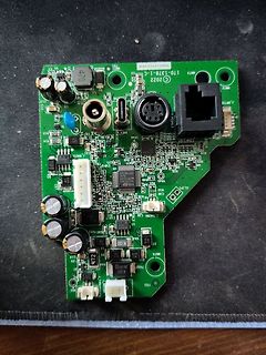
Leiterplatte eines Thrustmaster-Controllers
THRUSTMASTER 170-1378-1-C 2022 C J 09130 PEDALS WHEEL CLIP J THERM 470 472 470 C14 C15 C17 C19 C21 C24 C25 C26 C27 C28 C30 C31 C32 C33 C34 C35 C36 C37 C38 C39 C40 C41 C42 C43 C44 C45 C46 C47 C48 C49 C50 C51 C52 C53 C54 C55 C56 C57 C58 C59 C60 C61 C62 C63 C64 C65 C66 C67 C68 C69 C70 C71 C72 C73 C74 C75 C76 C77 C78 C79 C80 C81 C82 C83 C84 C85 C86 C87 C88 C89 C90 C91 C92 C93 C94 C95 C96 C97 C98 C99 C100 R1 R2 R3 R4 R5 R6 R7 R8
in „stm32L412 Code 43“ · Mikrocontroller und Digitale Elektronik · · Platinenfotos
-
PDF
edip128-6e.pdf
Issue 04.2022 EA eDIP128-6 Intelligent HMI 128x64 , RS-232, SPI, I2C Dimension: 71.4x54.4x13.6mm EAeDIP128B-6LWTP EAeDIP128W-6LWTP TECHNICAL DATA * LCD-GRAPHICDISPLAYWITHARANGEOFGRAPHICFUNCTIONS * 3DIFFERENTINTERFACESONBOARD:RS-232,I²C-BUSORSPI-BUS
-
PDF
DSxE.pdf
DS4E-S-DC6V (200mW) 9 DS1E-S-DC9V DS2E-S-DC9V DS4E-S-DC9V type 12 DS1E-S-DC12V DS2E-S-DC12V DS4E-S-DC12V 24 DS1E-S-DC24V DS2E-S-DC24V DS4E-S-DC24V 48 DS1E-S-DC48V DS2E-S-DC48V DS4E-S-DC48V 1 coil latching Part No. Nominal Voltage, V DC 1 Form C 2 Form C 4 Form C 1.5 DS1E-ML-DC1.5V DS2E-ML-DC1.5V DS4E-ML-DC1.5V
in „Relais Polung“ · Mikrocontroller und Digitale Elektronik ·
-
Datei
DDFS.vhd
"5b", x"5e", x"60", x"62", x"64", x"66", x"67", x"69", x"6b", x"6c", x"6e", x"70", x"71", x"72", x"74", x"75", x"76", x"77", x"78", x"79", x"7a", x"7b", x"7b", x"7c", x"7d", x"7d", x"7e", x"7e", x"7e", x"7e", x"7e", x"7f", x"7e", x"7e", x"7e", x"7e", x"7e", x"7d", x"7d", x"7c", x"7b", x"7b", x"7a", x"79", x"78", x"77", x"76", x"75", x"74", x"72", x"71", x"70", x"6e", x"6c", x"6b", x"69", x"67", x"66", x"64", x"62", x"60", x"5e", x"5b", x"59", x"57", x"55", x"52", x"50", x
in „Sinustabelle mit 2 Geschwindigkeiten“ · FPGA, VHDL & Co. ·
-
Datei
DDFS.vhd
"5b", x"5e", x"60", x"62", x"64", x"66", x"67", x"69", x"6b", x"6c", x"6e", x"70", x"71", x"72", x"74", x"75", x"76", x"77", x"78", x"79", x"7a", x"7b", x"7b", x"7c", x"7d", x"7d", x"7e", x"7e", x"7e", x"7e", x"7e", x"7f", x"7e", x"7e", x"7e", x"7e", x"7e", x"7d", x"7d", x"7c", x"7b", x"7b", x"7a", x"79", x"78", x"77", x"76", x"75", x"74", x"72", x"71", x"70", x"6e", x"6c", x"6b", x"69", x"67", x"66", x"64", x"62", x"60", x"5e", x"5b", x"59", x"57", x"55", x"52", x"50", x
in „Frequenz DDFS“ · FPGA, VHDL & Co. ·
-
PDF
MLX90223ESO.pdf
wall. It was designed to operate with a 5V mi- crocontroller from 3.75 to 5.25V DC and -40 to o +85 C. MLX UA 1 3 2 C1 D1 R1 Z1 Controller R= 115W D1 Used for Reverse Voltage Protection, -24v, -150V implu Z1 Used for over voltage Protection such as +24V, 150V im R1, C1 Work with the diodes and provide
in „Hallsensor prüfen mit multimeter“ · Analoge Elektronik und Schaltungstechnik ·
-
Datei
io.h-text.txt
linux-headers-4.15.0-39/arch/arm/mach-pxa/include/mach/io.h ./usr/src/linux-headers-4.15.0-39/arch/arm/mach-s3c24xx/include/mach/io.h ./usr/src/linux-headers-4.15.0-39/arch/arm/mach-ebsa110/include/mach/io.h ./usr/src/linux-headers-4.15.0-39/arch/arm/mach-footbridge/include/mach/io.h ./usr/src/linux-headers-4.15.0
in „Includes nicht gefunden“ · Mikrocontroller und Digitale Elektronik ·
-
PDF
spartan7.pdf
n 22u 22u 1 0 SD R25 C 1 D R 2 GND 6 LV GND GND GND 24 24_SS1 7_COMP2 7 N 10k D U$6 7 OSC C55 1 G GND GND T N N 8 16 20k6 7 U G E BEAD 8_SS2 16_BST3 C 4 R2_ L21 _ 15V 3 GND 10n C54 L2 0 L6 5V 5 P$2 P$3 C112L13 C117 C118 17
in „FPGA Board mit FT2232H und Spartan7“ · Projekte & Code ·
-
PDF
at91sam.pdf
PB13 F2 PB23 H7 PA9/PGMM1 A3 PA20/PGMD8 C8 PA13/PGMD1 F3 PB25 H8 PA8/PGMM0 A4 PB1 C9 PA12/PGMD0 F4 PB26 H9 PB29/AD2 A5 PB7 C10 PA15/PGMD3 F5 TCK H10 PLLRC A6 PB5 D1 PA23/PGMD11 F6 PA6/PGMNOE J1 PA29 A7 PB8 D2 PA24/PGMD12 F7 ERASE J2 PA30 A8
in „SPI-Initialisierung von zwei Geräte über den gleichen Bus“ · Mikrocontroller und Digitale Elektronik ·
-
Datei
lcd-m50530.c
char c; while ((c = pgm_read_byte(progmem_string++))) LCD_writeChar(c); } // setzt den Cursor an die angegebene Position (y = Zeile, x = Spalte) void LCD_setCursorPos(const unsigned char y, const unsigned char x) { // Adresse aus x und y berechnen // Adressen sind wie folgt: Zeile 0 = 0; Zeile 1 = 64; Zeile 2 = 128; Zeile 3 = 192; Zeile 4 = 0+24; Zeile 5 = 64+24; Zeile 6 = 128+24; Zeile 7 = 192+24 unsigned char address = x + ((y % 4) << 6); if (y > 3) address += 24; LCD_sendByte(address, (1<<LCD_OC1
in „LCD-Problem nach Änderung der Pinbelegung“ · Mikrocontroller und Digitale Elektronik ·
-
Datei
G32trust.asm
cx, byte ptr [ebx+7] mov eax, 1 loc_10001368: ; CODE XREF: gt_CheckTrustFund+64 j movzx dx, byte ptr [ebx+eax+7] xor ecx, edx inc eax cmp eax, 1Bh jb short loc_10001368 mov ax, [ebx+22h] mov [esp+0A8h+var_8C], ecx mov [esp+0A8h+var_88], eax lea eax, [ebx+24h] mov cx, word ptr [esp
in „Wer kann mir eine ASM File compelieren“ · Softwareentwicklung ·
-
PDF
DS4E-M-DC1.5V-Panasonic.pdf
DS2E-S-DC6V DS4E-S-DC6V type 9 DS1E-S-DC9V DS2E-S-DC9V DS4E-S-DC9V 12 DS1E-S-DC12V DS2E-S-DC12V DS4E-S-DC12V 24 DS1E-S-DC24V DS2E-S-DC24V DS4E-S-DC24V 48 DS1E-S-DC48V DS2E-S-DC48V DS4E-S-DC48V 1 coil latching Part No. Nominal Voltage, V DC 1 Form C 2 Form C 4 Form C 1.5 DS1E-ML-DC1.5V DS2E-ML-DC1.5V DS4E-ML-DC1.5V
in „"Merkwürdiges" Relais.“ · Analoge Elektronik und Schaltungstechnik ·
-
PDF
Inbetriebnahme__Wartung_und_Service_Eurola.pdf
lungsbrenner, bauseits umgestellt auf 8 bis 11ĂkW ErdgasĆAusführung - Raumbeheizung V R āā=āā75/60 ºC kW 8 bis 11 8 bis 15 8 bis 18 14 bis 24 V R āā=āā40/30 ºC kW 8,9 bis 12,5 8,9 bis 16,5 9,1 bis 20,4 15,3 bis 26,3 - Trinkwassererwärmung kW 8 bis 18 8 bis 18 8 bis 22 14 bis 24 FlüssiggasĆAusführung
in „Schaltplan/Hilfe bei Steuerung Eurola OC“ · Haus & Smart Home ·
-
PDF
swBalancer.pdf
DISPLAY-OLED-128X64-I2C 128x64 OLED 3 +3V3 +3V3 U$4 3 + Konstantstrommodus nach https://www.mikrocontroller.net/topic/444512 A L C D D C C N MWSA1004-220MT R57 R56 S S V G +3V3 L2 10k 10k TME DE0703-22 R5 D7 4 3 2 1 SpiceSpiceOrder
in „SuperCap Balancer mittels µC“ · Analoge Elektronik und Schaltungstechnik ·
-
 Bild
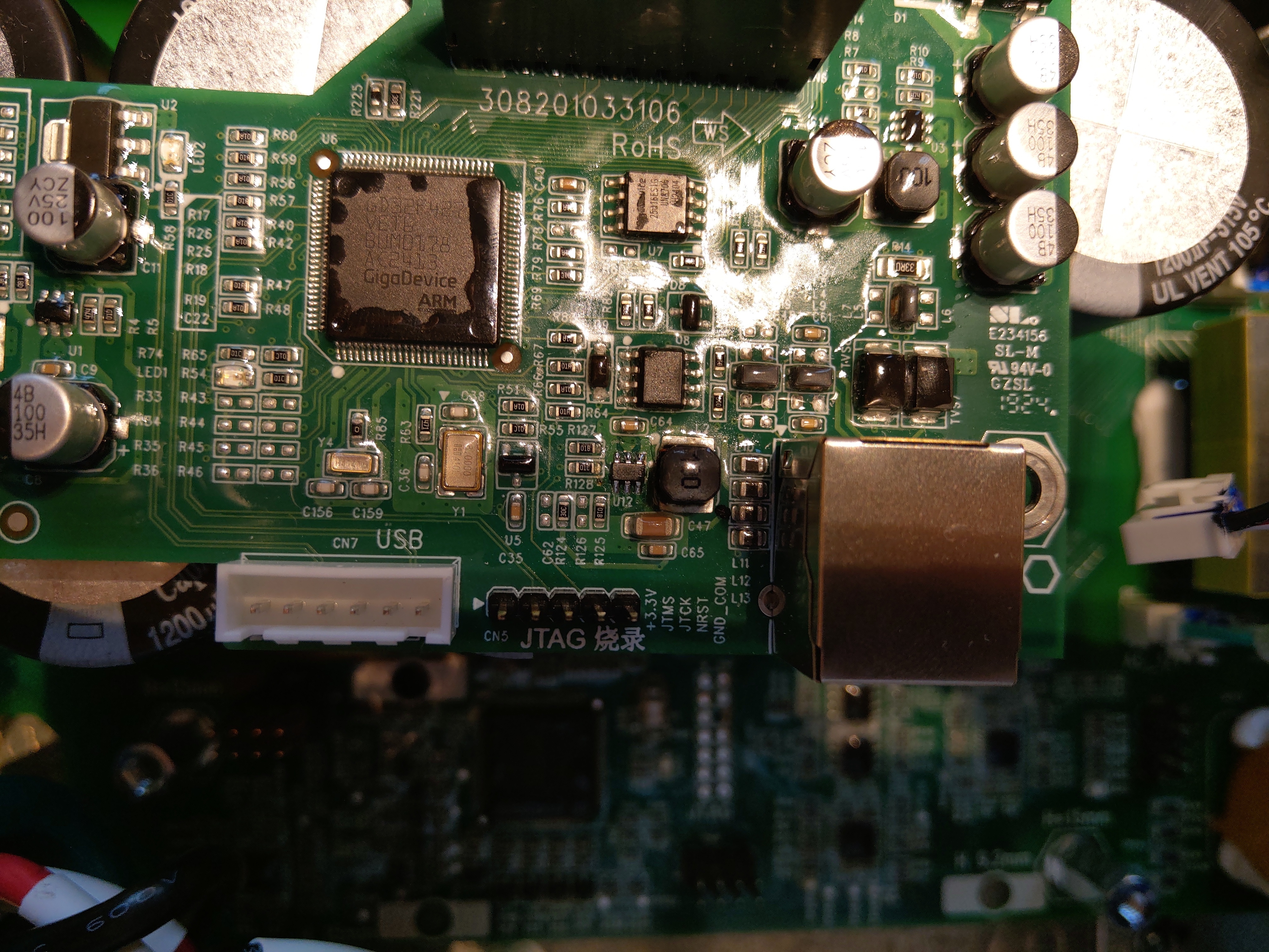
Nahaufnahme einer Leiterplatte mit GigaDevice ARM Mikrocontroller
R56 R55 R54 R53 R52 R51 R50 R48 R47 R46 R45 R44 R43 R42 R41 R36 R35 R35 R34 R33 R32 R31 R30 R26 R25 R24 R23 R22 R21 R20 R18 R17 R16 R15 R14 R13 R12 R11 R10 R9 R8 R7 R6 R5 R4 R3 R2 R1 C156 C159 C52 C54 C56 C58 C60 C62 C64 C66 C68 C70 C72 C74 C76 C78 C80 C82 C84 C86 C88 C90 C92 C94 C96 C98 C100 C102 C104 C106 C108 C110 C112 C114 C116 C118 C120 C122 C124 C126 C128 C130 C132 C134 C136 C138 C140 C142 C144 C146 C148 C150 C152 C154 D10 D12 D14 D16 D18 D20 D22 D24 D26 D28 D30 D32 D34 D36 D38 D40 D42 D44 D46
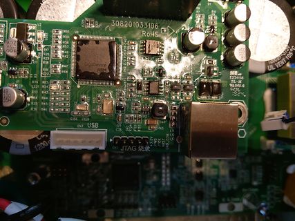
in „Solax Wechselrichter Mikrocontroller defekt?“ · Mikrocontroller und Digitale Elektronik · · Platinenfotos
-
PDF
Littelfuse_TVS_Diode_P6KE_Datasheet.pdf
Pricing, Inventory, Delivery & Lifecycle Information: Littelfuse: P6KE510AP6KE110CAP6KE11CAP6KE170P6KE24P6KE300CAP6KE68CP6KE220AP6KE10CA-B P6KE13A P6KE15A-B P6KE18A P6KE200C P6KE56CA P6KE12A-B P6KE150A-B P6KE250C P6KE110A P6KE160 P6KE16CA P6KE200A P6KE24CA P6KE36A P6KE6.8CA P6KE400A P6KE51CA P6KE350CA P6KE120A
in „PhotoMos mit TVS schützen ?“ · Analoge Elektronik und Schaltungstechnik ·
-
PDF
Sony_M610__MBX-176_.pdf
VCC_AXG_NCTF59 AL21 VCC_AXM2 AT31 BL33 VCC_SM35 VCC_AXG_NCTF60 AL23 M VCC_AXM3 AK29 AU30 AM15 +1_05VRUN X AK24 VCC_SM36 VCC_AXG_NCTF61 AM16 A VCC_AXM4 AK23 VCC_AXG_NCTF62 AM19 AL24 VCC_AXM5 AJ26 VCC_AXG VCC_AXG_NCTF63 AM20 AL26 VCC_AXM_NCTF1 C VCC_AXM6 AJ23 VCC_AXG_NCTF64 AM21 AL28 VCC_AXM_NCTF2 C VCC_AXM7 R20
in „Blitzschaden an Sony Vaio Notebook“ · PC Hard- und Software ·
-
Datei
main.c
,0x3b,0x3c,0x3d,0x3e,0x3f, 0x40,0x41,0x42,0x43,0x44,0x45,0x46,0x47,0x48,0x49,0x4a,0x4b,0x4c,0x4d,0x4e,0x4f, 0x50,0x51,0x52,0x53,0x54,0x55,0x56,0x57,0x58,0x59,0x5a,0x5b,0x5c,0x5d,0x5e,0x5f, 0x60,0x61,0x62,0x63,0x64,0x65,0x66,0x67,0x68,0x69,0x6a
in „Falsche Ausgangsfrequenz“ · Mikrocontroller und Digitale Elektronik ·
-
PDF
XMega-FPGA_V0.0.01.pdf
C_FPGA_D3/A3/A11/2.5C 139 64 FPGA_FLASH_MOSI 138 IO_L3N_0 IO_L3N_MOSI_CSI_B_MISO0_2 62 C_FPGA_D2/A2/A10/2.5C 137 IO_L4P_0 IO_L12P_D1_MISO2_2 61 FPGA_IO_26/4.6D C_FPGA_D1/A1/A9/2.5C 134 IO_L4N_0 IO_L12N_D2