Conditios Value Symbol Parameter V V V V T * 25 C T * Unit IS EE SS DD LOW HIGH (V) (V) (V) (V) Min. Max. Min. Typ. Max. Min. Max. L Quiescent 5 5 0.04 5 150 Supply HCC 10 10 0.04 10 300 Current types 15 20 0.04 20 600 A 20 100 0.08 100 3000 5 20 0.04 20 150 HCF 10 40 0.04 40 300 types 15 80 0.04 80 600
Parameter Conditions Standard-mod Fast-mode Fast-mode Unit 2 2 2 e IC-bus I C-bus Plus I C-bus Min Max Min Max Min Max SCL SCL clock frequency 0 100 0 400 0 1000 kHz BUF bus free time 4.7 - 1.3 - 0.5 - s between a STOP and START condition HD;STA hold time (repeated) 4.0 - 0.6 - 0.26 - s START condition
latches; 3-state RECOMMENDED OPERATING CONDITIONS 74HC 74HCT SYMBOL PARAMETER CONDITIONS UNIT MIN. TYP. MAX. MIN. TYP. MAX. VCC supply voltage 2.0 5.0 6.0 4.5 5.0 5.5 V VI input voltage 0 − VCC 0 − V CC V VO output voltage 0 − VCC 0 − V CC V Tamb ambient temperature −40 − +125 −40 − +125 °C r f t input rise
latches; 3-state RECOMMENDED OPERATING CONDITIONS 74HC 74HCT SYMBOL PARAMETER CONDITIONS UNIT MIN. TYP. MAX. MIN. TYP. MAX. VCC supply voltage 2.0 5.0 6.0 4.5 5.0 5.5 V VI input voltage 0 − VCC 0 − V CC V VO output voltage 0 − VCC 0 − V CC V Tamb ambient temperature −40 − +125 −40 − +125 °C r f t input rise
latches; 3-state RECOMMENDED OPERATING CONDITIONS 74HC 74HCT SYMBOL PARAMETER CONDITIONS UNIT MIN. TYP. MAX. MIN. TYP. MAX. VCC supply voltage 2.0 5.0 6.0 4.5 5.0 5.5 V VI input voltage 0 − VCC 0 − V CC V VO output voltage 0 − VCC 0 − V CC V Tamb ambient temperature −40 − +125 −40 − +125 °C r f t input rise
latches; 3-state RECOMMENDED OPERATING CONDITIONS 74HC 74HCT SYMBOL PARAMETER CONDITIONS UNIT MIN. TYP. MAX. MIN. TYP. MAX. VCC supply voltage 2.0 5.0 6.0 4.5 5.0 5.5 V VI input voltage 0 − VCC 0 − V CC V VO output voltage 0 − VCC 0 − V CC V Tamb ambient temperature −40 − +125 −40 − +125 °C r f t input rise
RIGHT ANGLE DIP TYPE; S: STRAIGHT DIP TYPE; C. NO. OF PINS. APPLY THE LEVEL CONDITION OF DC 20mV ImA MAX. FOR THE OPEN INITIAL RESISTANCE D. CONTACT AREA: CONTACT CIRCUIT VOLTAGE AND DC 10mA Max. FOR THE CLOSED CIRCUIT Ri 60m OHM 3 RESISTANCE CURRENT .THEN MEASURE THEM THAT BETWEEN EACH COUPLED AFTER TEST
Regulator OFF) 0.8 V EN Pin Input Leakage IH VEN =2V (ON) 1 15 uA Current IL V EN=0V (OFF) 1 15 uA Max. Duty Cycle DMAX VFB0V 100 % Rev 2.2 www.xlsemi.com 5 Datasheet 5A300KHz 32VBuck DC to DC Converter XL4005 Test Circuit and Layout guidelines CFF LOCATE THE PROGRAMMING RESISTORS NEAR THE FEEDBACK PIN
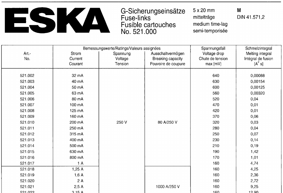
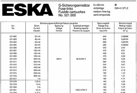
Ausschaltvermögen Breaking capacity Pouvoir de coupure Spannungsabfall Voltage drop Chute de tension max [mV] Schmelzintegral Melting integral ∫ fusion [A²s] 521.002 32 mA 640 0,00088 521.003 40 mA 630 0,00154 521.004 50 mA 600 0,00125 521.005 63 mA 560 0,00320 521.006 80 mA 520 0,04 521.007 100 mA 470
TYPICAL PERFOR A CE CHARACTERISTICS IBAT2 vs Temperature and Supply Voltage IBAT1 vs V BAT IBAT2 vs VBAT 190 52 190 RPROG = 2.1k VCC = 5V VCC = 5V PNP = FCX589 T = 25°C T = 25°C RA = 7.5k RA = 2.1k PROG PROG PNP = FCX589 PNP = FCX589 ) ) A A A BAT PIN MUST BE DISCONNECTED ( ( ( AND GROUNDED TO FORCE T180 V
VIEW TOP VIEW EXPOSED A1 A TIE BAR A3 (NOTE 3) Units INCHES MILLIMETERS * Dimension Limits MIN NOM MAX MIN NOM MAX Number of Pins n 8 8 Pitch e .020 BSC 0.50 BSC Overall Height A .031 .035 .039 0.80 0.90 1.00 Standoff A1 .000 .001 .002 0.00 0.02 0.05 Contact Thickness A3 .008 REF. 0.20 REF. Overall Length
.................................... 3. Revise Max t , t RromF15ns to 40ns in Table 11 - 8080-Series MPU Parallel Interface Timing Characteristics .......................................................................................................................................... 4. Revise Max t , t RromF15ns to 40ns in Table 12 – Serial Interface Timing Characteristics.....................d Table 1 - Ordering Information....................................................................
FBEoGSFF▯BTTFNCMZ t TP p -Temperature Min (T ) 150°C s(min) Ramp-up CTito Tl Zone Pre Heat -Temperature Max (T ) 200°C TL L P s(max) ) tL -Time (min to max) (t ) ▯▯▯o▯▯▯▯▯TFDT (Ts(max) s u Average ramp up rate (LiquidusTemp r Ramp-down 3°C/second max pTs(min) (TL) to peak m s T Preheat TS(max)oTL- Ramp-up Rate 3°C/second max -Temperature (T L (Liquidus) 217°C 25˚C t 25˚C to Peak Reflow -Time (min to max) (ts) ▯▯▯o▯▯▯▯▯TFDPOET Time (t) +0/-5 PeakTemperature (T )P 260 °C Time within 5°C of actual peak ▯▯▯o▯▯▯▯TFDPOET Temperature
Dieses Teil? https://www.youtube.com/watch?v=17im1J1EdZA Ist der Sensor überhaupt präzise genug? MAX30100 habe ich für 2 euro bestellt. Einfach nur um es mal zu beschnuppern.
Max B. schrieb im Beitrag #6082910: > Jemand der ein Produkt entwickelt ohne zu wissen ob es dafür einen Markt > gibt, der hat was falsch gemacht. Nicht unbedingt. Wenn man Geld zum verzocken zur Verfügung
parasitären Induktivitäten und Kapazitäten machen den Spass schnell zunichte. Kurzwelle und NDB Band (190-535 kHz) werden aber noch benutzt. https://en.wikipedia.org/wiki/Non-directional_beacon Damit kann man auch Peilen üben.
extra einen Sender auf > und lässt sich vorher eine Frequenz zuweisen?!). Das sind Stationen mit max. 1 Watt Strahlungsleistung wimre. Die BBC Sendeanlagen auf MW werden in der letzten Zeit auch immer weniger.
Bemessungswerte / Ratings: I - t Verhalten / I - t characteristics: N N BC_AC / 2 Art. No. I U N_AC / DC U d_max P d_max I t Bemessungs- Schmelzzeit N [V] [mV] [W] DC [A s] [A] strom-Faktor / 520.602 2) 32 mA 250 / 60 10.000 1,6 35 / 0,32 0,00008 / Melting time: 2) Rated current 520.603 40 mA 250 / 60 8.000 1,6
Ladeschaltung) und die Gleichrichterdioden neu dimensionieren. Über die Diode D1 (Spannungsregler) fließen nur max. ca. 70mA Übrigens: Ohne die Diode D2 gibt es leider Probleme. lg PoWl
einen 47 Ohm Widerstand verwendet und verschiedene Siebkapazitäten. Der Strom belief sich auf ca. 190-220 mA. Siebung Spannung 1N4148 Spannung 1N4001 ------------------------------------------------ 100µF 8,31 8,61 200µF 9,04 9,43 300µF
der Belegschaft oder die Austauschrate von 20 Jahren! Das jetzt Aufgrund der Rente mit 63 vllt. max 5% der Belegschaft auf die nächsten 5 Jahre mehr ausscheidet, macht einen Mehrbedarf von max. 1500 MA aus. Also sind da noch vll. 3000 Neueinstellungen als Normalrate zu sehen! Immer wieder erstaunlich
der Belegschaft oder die Austauschrate von 20 Jahren! > Das jetzt Aufgrund der Rente mit 63 vllt. max 5% der Belegschaft auf die > nächsten 5 Jahre mehr ausscheidet, macht einen Mehrbedarf von max. 1500 > MA aus. > Also sind da noch vll. 3000 Neueinstellungen als Normalrate zu sehen! > > Immer
and 7. DS21503 Rev. 10 - 2 1 of 4 1.5KE6V8(C)A - 1.5KE400(C)A www.diodes.com ã Diodes Incorporated Max. Max. Max. Type Type Reverse Breakdown Voltage Reverse Clamping Max. Voltage Number Number Standoff V @ I Current Leakage Voltage Pulse Temp. (Note 1) (Note 1) Voltage BR T (Note 2) @ I Current Variation @ V R pp of VBR (UNI) (BI) VRWM (V) Min (V) Max (V) It(mA) R (mA) V CV) PP (A) %/°C 1.5KE6V8A 1.5KE6V8CA 5.80 6.45 7.14 10 1000 10.5 143.0 0.057 1.5KE7V5A 1.5KE7V5CA 6.40 7.13 7.88 10 500 11.3 132.0 0.061 1.5KE8V2A 1.5KE8V2CA 7.02 7.79 8.61 10 200
its usage. */ //#define MAX7219_DEBUG #if ENABLED(MAX7219_DEBUG) #define MAX7219_CLK_PIN 64 #define MAX7219_DIN_PIN 57 #define MAX7219_LOAD_PIN 44 //#define MAX7219_GCODE // Add the M7219 G-code to control the LED matrix #define MAX7219_INIT_TEST 2 // Test pattern at startup: 0=none, 1=sweep, 2=spiral #define MAX7219_NUMBER_UNITS 1 // Number of Max7219 units in chain. #define MAX7219_ROTATE 0 // Rotate the display clockwise (in
Max. switching voltage (VDE 0435) 380 VAC 380 VAC 380 VAC Max. switching powe3)with resistive load in AC 1250 VA 2500 VA 4000 VA Max. switching power in DC see diagram 3 see diagram 3 see diagram 3 Life ( see diagram 1) Expected life at max. resistive load and repetition at: 1000 cycles /h 3 x 10 5 2 x 10 5 3 x 10⁵ 7.5 x 10⁴ 10 cycles 500 cycles/h 3.5 x 10⁵ 2.5 x 10⁵ 3.5 x 10⁵ 8 x 10⁴ 1.5 x 10⁵ Max. electrical repetition rate 3600 cycles
62] FFFh Maximum read current at VDD,min VDD_R_CURR_MIN 3 R [61:59] 7h Maximum read current at VDD,max VDD_R_CURR_MAX 3 R [58:56] 7h Maximum write current at V VDD_W_CURR_MIN 3 R [55:53] 7h DD,min Maximum write current at DD,max VDD_W_CURR_MAX 3 R [52:50] 7h Device size multiplier C_SIZE_MULT 3 R [49
Übergabewert temp1 ist 127 entspricht 1 Oktave ;; Minimale Frequenz 440Hz @4MHz => temp2 = 4MHz/2/440/temp1_max/3-1= 5 WAIT: _WAIT1: ldi temp2, $05 ;(1)*temp1 _WAIT2: dec temp2 ;(1)*temp2*temp1 brne _WAIT2 ;((2)*temp2-(1)) * temp1 dec temp1 ;(1)*temp1 brne _WAIT1 ;(2)*temp1-(1) ret tonleiter: ;; c d e f g a h c Terminierung .db 254, 226, 202, 190, 170, 151, 135, 127, 0
Übergabewert temp1 ist 127 entspricht 1 Oktave ;; Minimale Frequenz 440Hz @4MHz => temp2 = 4MHz/2/440/temp1_max/3-1= 5 WAIT: _WAIT1: ldi temp2, $05 ;(1)*temp1 _WAIT2: dec temp2 ;(1)*temp2*temp1 brne _WAIT2 ;((2)*temp2-(1)) * temp1 dec temp1 ;(1)*temp1 brne _WAIT1 ;(2)*temp1-(1) ret tonleiter: ;; c d e f g a h c Terminierung .db 254, 226, 202, 190, 170, 151, 135, 127, 0
Facharbeiterstelle zu haben. Vor ca. 150 Jahren war das aber auch nicht viel anders. 1899 erschien von Max Eyth das deutlich autobiographisch geprägte Werk "hinter Pflug und Schraubstock". Darin beschreibt er auch seine eigene (und auch die einiger Kollegen) beschwerliche Suche nach einer Arbeitsstelle
ist dem damaligen Zeitgeist geschuldet. Aus der Geschichte lässt sich oft gut etwas lernen. Max Eyth hat dann schließlich doch noch Karriere gemacht. Das wird vielen anderen nicht geglückt sein, aber die haben halt nicht davon berichtet. Survivorship Bias halt. Siehe: https://de.wikipedia.org
electrolytic capacitors 085 CS SMD (Chip) Standard MECHANICAL DATA handbook, halfpage handbook, halfpage 2 max 2 max max9 2 max 2 max max9 2.7 2.7 2.7 2.7 max max max max 4.1 3.9 4.1 3.9 max max max max 7.5 10.8 9 max MGB099 - 1 12.2 max MGB100 - 1 a. b. Dimensions in mm. a. Case size 8.8 × 3.7 × 3.9 mm. b.
sheet BMA020 Bosch Sensortec Digital, triaxial acceleration sensor Parameter Symbol Condition Min Typ. Max Units Bandwidth bw 2 order analog 1500 Hz filter Digital filter 25, 50, 100, Hz 190, 375, 750 Acceleration data f_rate 2700 3000 3300 Hz refresh rate (all axes) Nonlinearity NL Best fit straight lin
sheet BMA020 Bosch Sensortec Digital, triaxial acceleration sensor Parameter Symbol Condition Min Typ. Max Units Bandwidth bw 2 order analog 1500 Hz filter Digital filter 25, 50, 100, Hz 190, 375, 750 Acceleration data f_rate 2700 3000 3300 Hz refresh rate (all axes) Nonlinearity NL Best fit straight lin
Lead* 500 Units/Box (Lead Length w 1/16″ from Case, 10 s Max) Stresses exceeding Maximum Ratings may damage the device. Maximum MKP3V240G Axial Lead* 500 Units/Box Ratings are stress ratings only. Functional operation above the Recommended Operating Conditions
Data Sheet IPB180P04P4L-02 ® OptiMOS -P2 Power-Transistor Product Summary V DS -40 V R 2.4 DS(on),max mW ID -180 A Features PG-TO263-7-3 • P-channel - Logic Level - Enhancement mode • AEC qualified • MSL1 up to 260°C peak reflow • 175°C operating temperature • Green Product (RoHS compliant) • 100% Avalanche
) P3/FS277 o DC Electrical Characteristics (at Ta = 25 C) PARAMETER SYMBOL TEST CONDITIONS MIN TYP MAX UNIT Operating Voltage V No use pin is open (Fig1) 3 - 20 V CC No use pin is open V : 3V Quiescent Supply current ICC cc - 18 20 mA to 20V (Fig1) Output Leakage current Ileak Vcc=12V, Vce=20V - <0.1
Fcco wichtig, bzw: was muss ich dort eintragen, wenn ich auf 120mhz auftakten möchte ? Wenn ich im Max-Cpu Feld 120 eintrage, dann ist es ein ungültiger Wert. Kann mir das bitte jemand erklären, bzw: mir einfach die Werte für die Initialisierung für 120Mhz Systemtakt bei 25Mhz Fin geben ?
maintain regulation depends on the load current and output voltage, and is calculated as: V Iin = V O max + I O max× r( DS(on) max + R (L) ) (2) with: IOmax = maximum output current plus inductor ripple current r max = maximum P-channel switch r DS(on) DS(on) R (L) dc resistance of the inductor V Oax =
maintain regulation depends on the load current and output voltage, and is calculated as: V Iin = V O max + I O max× r( DS(on) max + R (L) ) (2) with: IOmax = maximum output current plus inductor ripple current r max = maximum P-channel switch r DS(on) DS(on) R (L) dc resistance of the inductor V Oax =
maintain regulation depends on the load current and output voltage, and is calculated as: V Iin = V O max + I O max× r( DS(on) max + R (L) ) (2) with: IOmax = maximum output current plus inductor ripple current r max = maximum P-channel switch r DS(on) DS(on) R (L) dc resistance of the inductor V Oax =
maintain regulation depends on the load current and output voltage, and is calculated as: V Iin = V O max + I O max× r( DS(on) max + R (L) ) (2) with: IOmax = maximum output current plus inductor ripple current r max = maximum P-channel switch r DS(on) DS(on) R (L) dc resistance of the inductor V Oax =
maintain regulation depends on the load current and output voltage, and is calculated as: V Iin = V O max + I O max× r( DS(on) max + R (L) ) (2) with: IOmax = maximum output current plus inductor ripple current r max = maximum P-channel switch r DS(on) DS(on) R (L) dc resistance of the inductor V Oax =

 Bild
 Bild