truth, but the amount of extra voltage swing that is achieved is hard to calculate. Guaranteed min/max specifications define the limits of a parameter. The parameter will always exceed the minimum value, and it will never exceed the maximum value. The guaranteed min/max specifications are your design
Vb 1 7867 o t a l t ED ED ED s n I a b ED ED Va Vb a b ED ED Va Vb a b ED ED Va Vb 1 7867 ED ED ED max. 30 max. 30 max. 30 L N Va Vb L N Va Vb L N Va Vb 1 6481 L N 1 2 3 4 11 21 a1 b a2 b a3 b 1 7573 Va Vb Va Vb + E+ Va Vb Va Vb 1 4813 1 8783/ Va Vb 80 1 2 1 8789 LT 1 2 3 4 1 8759/ 1 8760 1 8753 S0251
terminal 1 3 2 1 G LIMITING VALUES Limiting values in accordance with the Absolute Maximum System (IEC 134). SYMBOL PARAMETER CONDITIONS MIN. MAX. UNIT -5001 -601 V DRM Repetitive peak off-state - 500 600 V voltages I RMS on-state current full sine wave; T ≤51 ˚C - 1 A T(RMS) lead ITSM Non-repetitive peak
differential pair, the transducer's layout used a cross-quad geometry. Variations in process parameter A .v max(A),max(B) min(A),max(B) Variations 1/2 of device 1 1/2of device 2 in process . parameter B l _ II _ max(A),min(B) min(A),min(B) F 1/2 of device 2 1/2 of device 1 Figure 3.15: Cross-quad layout sketch
Package imformation: DIP-8 Package: Symbo Dimensions In Millmeters Dimensions In Inches l Min Nom Max Min Nom Max A — — 4.31 — — 0.170 A1 0.38 — — 0.015 — — A2 3.15 3.40 3.65 0.124 0.134 0.144 B 0.38 0.46 0.51 0.015 0.018 0.020 B1 1.27 1.52 1.77 0.050 0.060 0.070 C 0.20 0.25 0.30 0.008 0.010 0.012 D
höher als VDD +0,3 V müssen die internen Pull-Up- und Pull-Down-Widerstände deaktiviert werden. 3. TA(max) gilt für PD(max). Bei PD < PD(max) darf die Umgebungstemperatur höher als TA(max) sein, vorausgesetzt, dass die Sperrschichttemperatur TJ TJ(max) nicht überschreitet . Siehe Abschnitt 6.5: Thermische
for the primary coil, the magnetic ux density B will be 115.21mT. Because the *VZK* voltage can vary max,L2 in the range of 7.50V to 16.50V B max,L2 will also vary between 72.00mT and 158.41mT (equation (68)). U ∗V ZK∗ 12.00V B max,L2 = 4 · n · f · A = 4 · 7 · 120kHz · 31mm 2 = 115.21mT (68) pri,L2 sw
Translated by Google PT4515HA Einzelsegment-Linear-LED-Treiberchip Millimeter Zoll Symbol Mindest Max Mindest Max A 1.350 1.750 0,053 0,069 A1 0,050 0,150 0,002 0,006 A2 1.350 1.650 0,053 0,065 B 0,330 0,510 0,013 0,020 C 0,170 0,250 0,007 0,010 D 4.700 5.100 0,185 0,201 D1 2.750 3.402 0,108 0,134 UND
θJC Electrical Characteristics (T =25℃unless otherwise noted) C Symbol Parameter Condition Min Typ Max Unit Off Characteristics BV DSS Drain-Source Breakdown Voltage V GSV I =D50μA 100 110 - V DSS Zero Gate Voltage Drain Current VDS100V,V =0GS - - 1 μA GSS Gate-Body Leakage Current VGS±20V,V =0DS - -
<a href="#fn48" class="footnote-ref" id="fnref48" role="doc-noteref"><sup>48</sup></a></p> <h2 id="max-max_y"> Max (max_y) </h2> <p>Softmaker Freeoffice wurde ja schon erwähnt. Momentan gibt es sogar das große Softmaker Office Paket kostenlos, ist aber die Version von 2021. Dennoch sicherlich einen Blick
2 7:0 AMAGCNDX AM AGC Index This byte reports the current AGC gain index. 0 = Minimum attenuation (max gain) 1 – 36+ATTN_BACKUP = Intermediate attenuation 37+ATTN_BACKUP = Maximum attenuation (min gain) Note: The max index is subject to change. See Property 0x3705 AM_FRONTEND_AGC_CONTROL for details
output impedance.IC to the active area + 1/160 1/12 7.93% e 6.3% 5.7% In addition, please limit the min-max spread of RC decay to 1/160 1/11 7.77% 6.2% 5.6% be: f i | RC MAX– RC MIN | < 0.15 S VIDEO CSTN & COG applications. For LCM with r ft = 180mS ~ 200mS or smaller, bottom of the screen are uniform.e top
USE EF 31 0 0x000000 Reset EFUSE_KEY3_DATA3 Stores the third 32 bits of KEY3. (RO) Espressif Systems 134 ESP32-C3 TRM (Version 1.1) Submit Documentation Feedback 4 eFuse Controller (EFUSE) GoBack Register 4.68. EFUSE_RD_KEY3_DATA4_REG (0x010C) TA _A KY SE EF 31 0 0x000000 Reset EFUSE_KEY3_DATA4 Stores
37.5A 0 ~ 19.0A 0 ~ 15.0A 0 ~ 12.7A 0 ~ 9.5A Rated Power 450W 456W 450W 457W 456W Ripple & Noise (Max.) Note.2<1% (mVp-p), according to the rated Output Voltage Output Voltage Adj. Range ±10% Typical adjustment by potentiometer Voltage Tolerance Note.3±1.0% Line Regulation ±0.5% Load Regulation ±0.5%
https://www.galaxus.ch/de/s1/product/schaffner-netzfilter-25a-520v-induktor-35853664?tagIds=1123-773-134-1560 Oder benötige ich eine Drossel wie diese hier? https://www.galaxus.ch/de/s1/product/siemens-ausgangsdrossel-390-a-01100-kw-induktor-19263705?tagIds=1123-773-134-1560 Oder sind Netzfilter
Kann das sein, dass die Leistungsangabe auch nicht stimmt? Ja, ich konnte den Generator mit max. 10 kW belasten, ehe die Drehzahl des Dieselmotors abrupt eingebrochen ist. Die Last bei meinem Versuch war aber nicht unbedingt sehr symetrisch, d. h. ich weiss nicht, ob ich mit einer symetrischen
USE EF 31 0 0x000000 Reset EFUSE_KEY3_DATA3 Stores the third 32 bits of KEY3. (RO) Espressif Systems 134 ESP32-C3 TRM (Version 1.1) Submit Documentation Feedback 4 eFuse Controller (EFUSE) GoBack Register 4.68. EFUSE_RD_KEY3_DATA4_REG (0x010C) TA _A KY SE EF 31 0 0x000000 Reset EFUSE_KEY3_DATA4 Stores
EPX880 & EPX8160: I = 12 mA DC, V = min., 0.2 V OL CCO current Note (4) I Input leakage current V = max., GND < V < V , Note (5) –10 10 A I CCO IN CCO OZ Output leakage current EPX880 & EPX8160: V CCO = max., OUT = VCCO –50 50 A EPX880 & EPX8160: V CCO = max., OUT = GND –100 100 A SC Output short circuit
to +85⋅C,CC = +2.7V to +5.5V,SS = 0V1, 2, 3 16MHz CLOCK VARIABLE CLOCK SYMBOL FIGURE PARAMETER MIN MAX MIN MAX UNIT 1/t 14 Oscillator frequency CLCL Speed versions :S 3.5 16 MHz t 14 ALE pulse width 85 2t –40 ns LHLL CLCL AVLL 14 Address valid to ALE low 22 tCLCL–40 ns LLAX 14 Address hold after ALE
Human body model, 100pF discharged through a 1.5kΩ resistor. (4) For elevated temperature operation,JT max is: LM134 150°C LM234 125°C LM334 100°C See Thermal Characteristics. Thermal Characteristics over operating free-air temperature range (unless otherwise noted) Thermal Resistance TO-92 TO SOIC-8 θjaJunction
von problemlosen Betrieb ausgehen kann. Das hängt auch von der Paketlänge ab. Beim AVR sind das max Startbit + 9 Datenbits + Parity + Stopbit = 12 Bitzeiten. Nur beim Startbit wird synchronisiert und beim 12. Bit sollten alle 3 Abtastzeitpunkte noch den gleichen Pegel haben. Damit kann man den genauen
der Wert noch halbiert werden, da die ja entgegengesetzt abweichen können. 3% je Teilnehmer, d.h. max 6% zusammen wird nicht mehr zuverlässig funktionieren. Das geht nur noch mit Baudratenquarz und 0% rechnerischer Fehler auf einer Seite. In der Praxis rechne ich den Fehler auf <1% aus, also max
format. NU_AIT_(2:0): Define the maximum number of AITs which are automatically requested by the ACQ (max 4). Table 12 User Set Table Column-Address C12, C13, C14 Char. Set 63 (User Set) 17 000 language number 18 100 language number 19 010 language number 20 110 language number 21 001 language number 22
100mH gewählt, als höchst verfügbaren Wert. Dann den Widerstand so hoch, dass der AD-Wandler beim max.-Strom (16A) vernünftig ausgesteuert wird. Und den Kern so groß, dass bei Max-Strom noch keine Sättigung stattfindet. Letztes führte dann allerdings zu dem recht fetten 20mm/30mm Kern. Eine Nummer
eine Wicklung angegeben, > doppelte Wdg bei Reihenschaltung würden 224mH (*4) ergeben. Deine > 134/4=33mH ist also eher die CAF-xx-39. Ja stimmt, da habe ich mich vertan. Der Serienwiderstand beider Spulen beträgt rund 2,2 Ohm. > Da du für 1R und 10R das fast gleiche Übersetzungsverhältnis
Das WL-134 Modul für u.a. FDX-B gibt die erkannten RFID Tags per UART aus, Beispielcode für den Arduino gibt es z.B. hier: https://github.com/Makuna/Rfid134
Zu dem WL-134 Modul dass ich hier erwähnt habe: Es gibt auch ein WL-134A, das kann im Gegensatz zum WL-134 zusätzlich mit HDX Transpondern umgehen. Für HDX hat das WL-134A ein RF-Frontend verbaut (TMS3705) von dem
Vor einigen Jahren hat ein belgischer OM mit einem aus Aluminium gefrästen Spiegel (max. 50 cm Durchmesser) den Empfang einer Mars-Sonde vorgeführt. Ich komme partout nicht auf das Rufzeichen, würde ihn aber auf einem Foto sofort wieder erkennen. Die Vorführung war echt spannend. Edit
Digikey "Stückpreis mit MwSt.: 246,49660 €" Die GHz-Chips: DUBUS 1/2024 S.65-92 "Want more? QSY to 134 GHz" (ohne Preisangabe): https://siliconradar.com/products/single-product/120-ghz-wide-band-transceiver-tra_120_045/ https://groups.io/g/The122GProject/wiki DUBUS 3/2024 S.65-95 "241-250GHz-Transverter
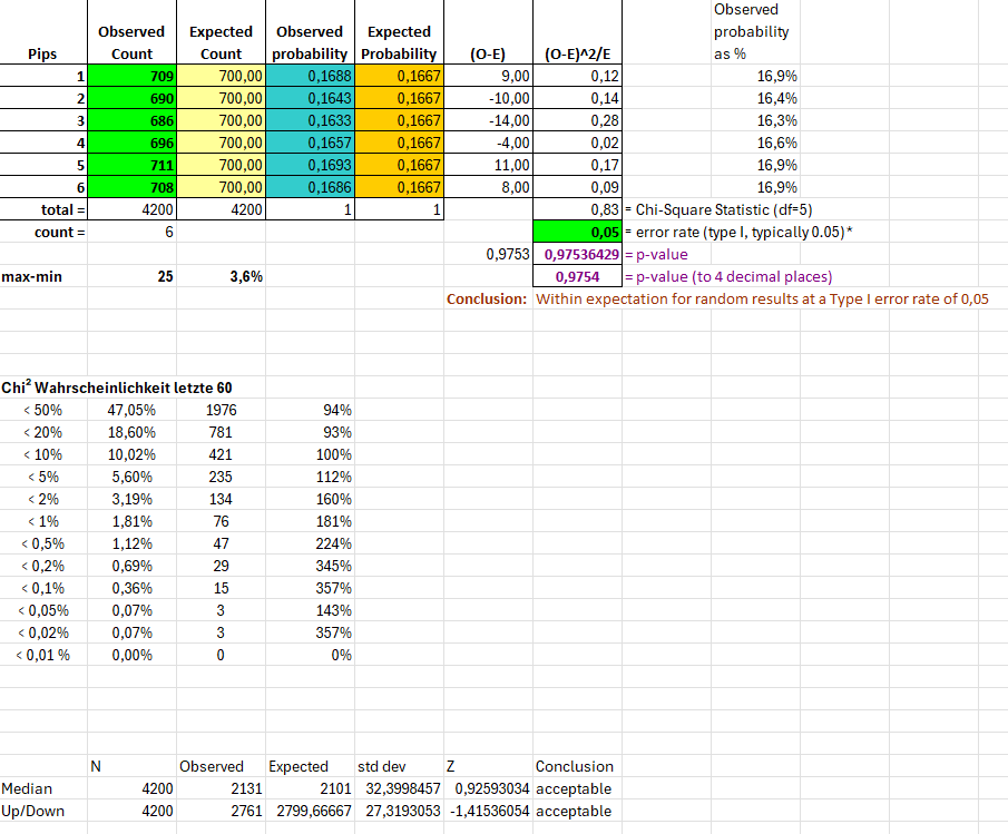
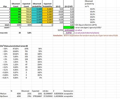
probability Expected Probability (O-E) (O-E)^2/E total = 4200 4200 1 1 0,83 = Chi-Square Statistic (df=5) max-min 25 3,6% p-value 0,9753 0,97536429 = p-value 0,9754 Conclusion: Within expectation for random results at a Type I error rate of 0,05 * 0,05 = error rate (type I, typically 0,05) Chi^2 Wahrscheinlichkeit
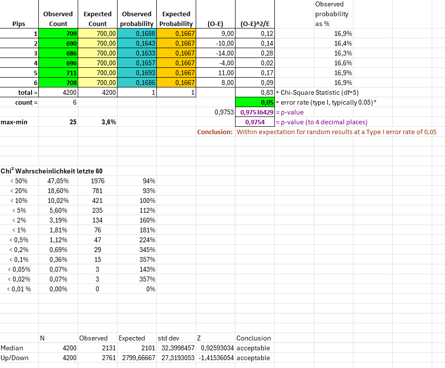
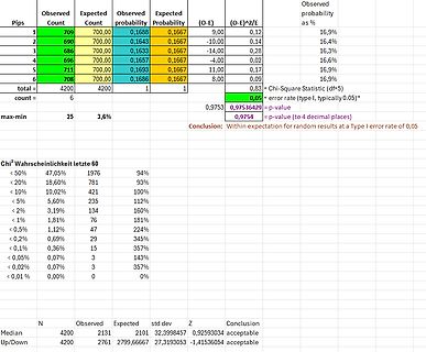
probability Expected Probability (O-E) (O-E)^2/E total = 4200 4200 1 1 0,83 = Chi-Square Statistic (df=5) max-min 25 3,6% p-value 0,9753 0,97536429 = p-value 0,9754 Conclusion: Within expectation for random results at a Type I error rate of 0,05 * 0,05 = error rate (type I, typically 0,05) Chi^2 Wahrscheinlichkeit
nachTimereinstellungen Programmieren und Schalten von Lichteffekten Technische Daten: Betriebsspannung: 9V~ Max. Stromaufnahme: 560 mA bei 9V~ und 8 eingeschalteten Relais Schaltleistung: 24V-/ 3A Maße: 102x134 mm 7 8
Ruckmeldung Eingang 1 “Steuerungstbetriebs- 1 bereit” I l l I L 1 2 3 2 t I 3 2 I 14 l I I I I I I I q max. 174ms max. 124~s Zeit Bemerkung Fehlermeldung l I 1 STROMUNTERBRECHUNG I 2 Yarten auf Steuerspannung STEUERSPANNUN FGUERRELAIS FEHLT 3 Nach Abschalten des Ausgangs “Steuerung betriebsbereit” muß innerhalb
große Chiller für unser Bürogebäude hat zwei dicke Bitzerkompressoren und eine Füllmenge von 40kg R134a pro Kreis Im Kreislauf des Klimawindkanals sind mehrere Tonnen ;-))
mich schon interessieren, um wie viel besser es geworden ist. Bei meinem Auto sind 2x ca. 0.5 kg R134a weg (also 2x 100%). Seitdem ist die leer und bleibt es auch ;-)
hat, die Technik dafür abzubauen. Nachdem sie jahrelang abgeschaltet > rumstand. Hier sind das max. 2,5 Jahre.
@ Reinhard S.: > Uwe schrieb: >> Hier sind das max. 2,5 Jahre. > Mir hat Telekom im Dezember 2018 "das neue Netz der Zunkuft" andrehen > wollen, Juli 2019 wurde dann mein ISDN abgeschaltet - 5 Jahre. Ich kann nur für meinen Fall schreiben. =
10,000 Cycles Contact position indicator Yes Protection degree IP20 Ambient temperature -5℃ to +40℃, Max.95% humidity Terminal connection type Cable/Pin-type busbar/Fork-type busbar 2 Max.terminal size for cable 25mm Max.tightening torque 2.5N.m Installation Mounting on 35mm DIN rail Connection From top
expander for I C-bus 8 LIMITING VALUES In accordance with the Absolute Maximum Rating System (IEC 134); note 1. SYMBOL PARAMETER MIN. MAX. UNIT VDD supply voltage −0.5 +6.5 V DD supply current − ±100 mA SS supply current − ±100 mA VI input voltage VSS− 0.5 VDD + 0.5 V I DC input current − ±20 mA I DC
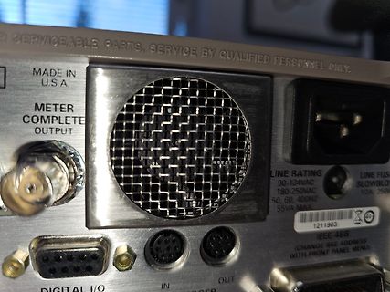
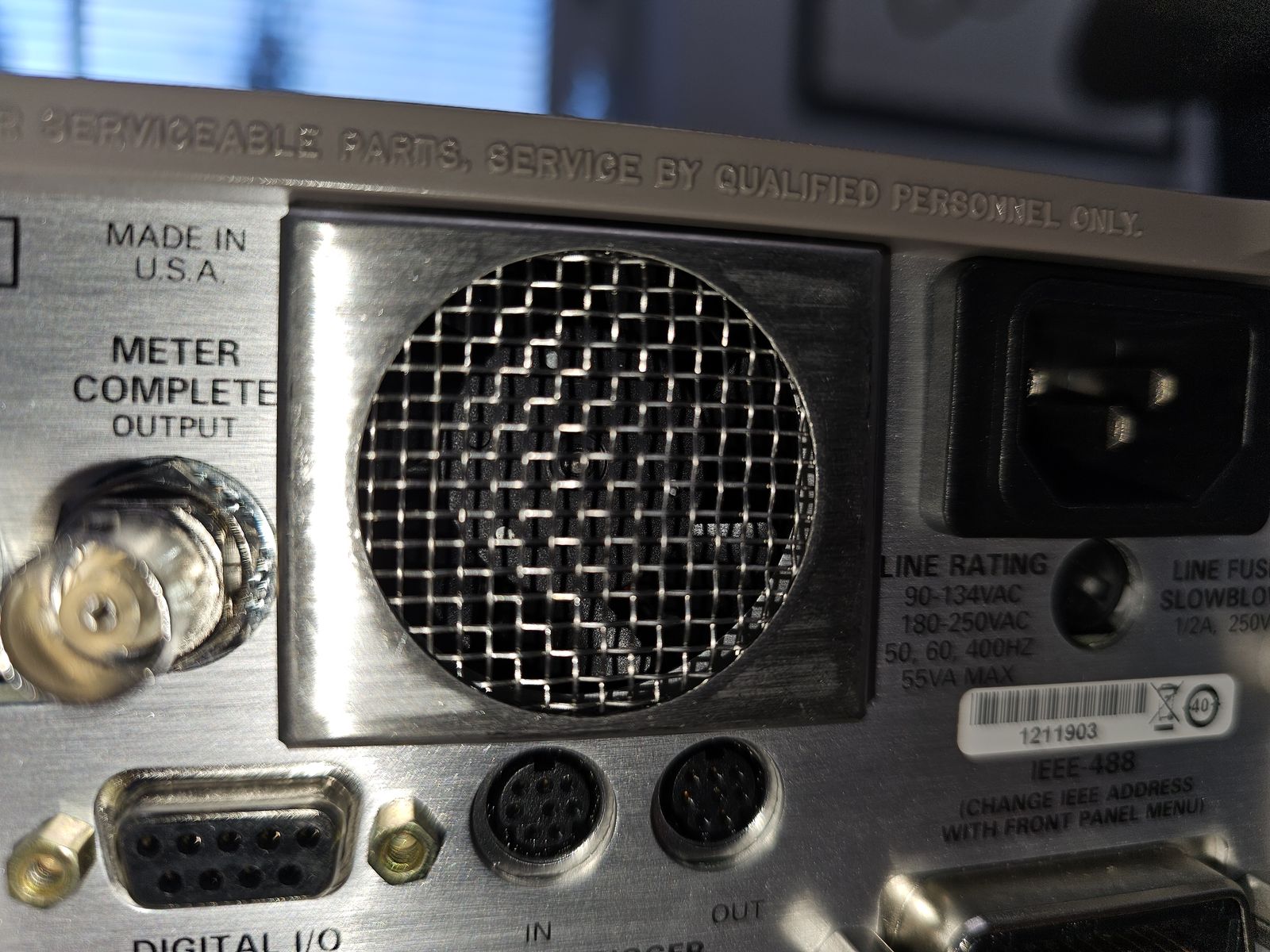
SERVICEABLE PARTS, SERVICE BY QUALIFIED PERSONNEL ONLY.
MADE IN U.S.A.
METER COMPLETE OUTPUT
LINE RATING 90-134VAC 180-250VAC 50, 60, 400HZ 55VA MAX
LINE FUSE SLOWBLOW 1/2A, 250V
1211903
IEEE-488 (CHANGE IEEE ADDRESS WITH FRONT PANEL MENU)
DIGITAL I/O IN OUT
which has two extreme values along the hysteresis curve Bx,1− B x,2 B x,1− B x,2 µmin = min , and µ max = max . (5.58) H x,1Hx,2H x,1− H x,2 Hx,1,Hx,2H x,1− H x,2 Hereµ min andµ max aretheminimumandmaximumslopeofthehysteresischaracteristics. The inequality µmin ≤ µ ≤ µ max (5.59) is obvious, from which
Kurzschluss die Verlustleistung abnimmt, nein. Man sieht an der Kurve für 10km/h das bei 12 Ohm 6V die max. Leistung abgegeben wird, das ist Leistungsanpassung, d.h. der Zi ist auch 12 Ohm, bei 20km/h ist die max Leistung bei mit Ri=22 Ohm erreicht, was bedeutet wir haben ein Zi=22 Ohm jetzt muss man
Durchlassspannung der Diode D3 reduziert. Die Bauteilewerte sind noch nicht fix. Q1/R1/D4 begrenzen die max. Ausgangsspannung und die Ladungspumpe C1/D1/D2 sorgt für eine minimale Sättingungsspannung von Q1 bei niedriger Stromaufnahme. Je nach Dynamo kann die max. Eingangsspannung mit D5/D6 begrenzt werden

 Bild
Bild
 Bild
Bild
 Bild
Bild
 Bild
Bild