<a href="#fn48" class="footnote-ref" id="fnref48" role="doc-noteref"><sup>48</sup></a></p> <h2 id="max-max_y"> Max (max_y) </h2> <p>Softmaker Freeoffice wurde ja schon erwähnt. Momentan gibt es sogar das große Softmaker Office Paket kostenlos, ist aber die Version von 2021. Dennoch sicherlich einen Blick
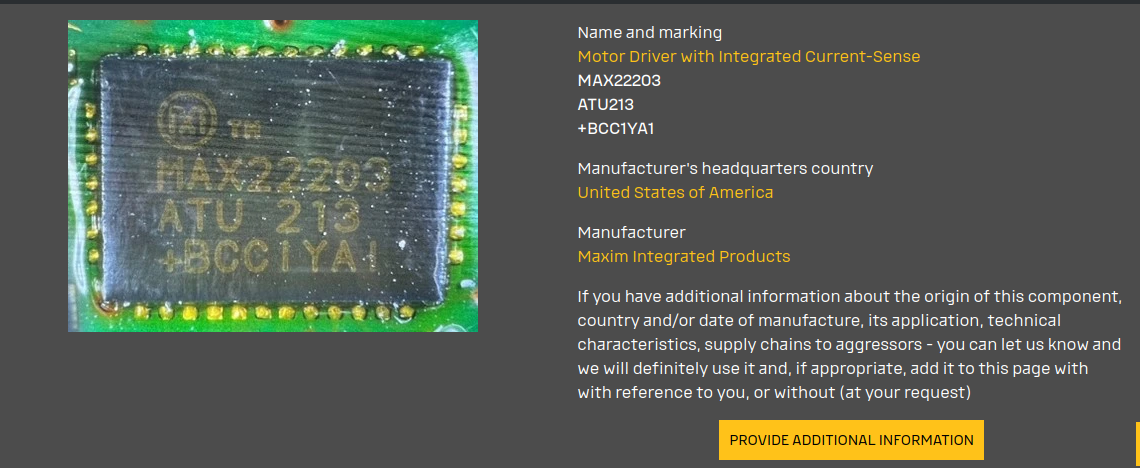
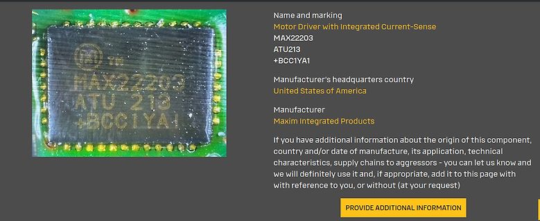
Name and marking
Motor Driver with Integrated Current-Sense
MAX22203
ATU213
+BCC1YA1
Manufacturer's headquarters country
United States of America
Manufacturer
Maxim Integrated Products
If you have additional information about the origin of this component, its
output impedance.IC to the active area + 1/160 1/12 7.93% e 6.3% 5.7% In addition, please limit the min-max spread of RC decay to 1/160 1/11 7.77% 6.2% 5.6% be: f i | RC MAX– RC MIN | < 0.15 S VIDEO CSTN & COG applications. For LCM with r ft = 180mS ~ 200mS or smaller, bottom of the screen are uniform.e top
Introduction 211 9.2 Features 211 9.3 Functional Description 211 9.3.1 Power Management Unit (PMU) 213 9.3.2 Low-Power Clocks 214 9.3.3 Timers 215 9.3.4 Voltage Regulators 216 9.3.4.1 Digital System Voltage Regulator 216 9.3.4.2 Low-power Voltage Regulator 216 9.3.4.3 Brownout Detector 217 9.4 Power
CHARACTERISTICS V = 12V, T = +25°C, unless otherwise noted. IN A Parameter Symbol Condition Min Typ Max Units Shutdown Supply Current VEN = 0V 0.3 3.0 µA Supply Current V = 2.0V, V = 1.0V 1.3 1.5 mA EN FB Feedback Voltage V FB 4.75V ≤ VIN≤ 23V 0.900 0.925 0.950 V Feedback Overvoltage Threshold 1.1 V Error
The maximum allowable continuous power dissipation at any ambient temperature is calculaDed by PTJ(MAX)- Lead Temperature ....................................260C TA/ JA. Exceeding the maximum allowable power dissipation Storage Temperature.............. –65°C to +150C will cause excessive die temperature
.. C/W All Other Pins..................................-D.3V t2) Tmaximum junction temperature T (MAX), the junction-to-f the SOIC8……………………………………….1.38Won......(TA= +25°C)..(2).150°C TA. The maximum allowable continuous power dissipation ate Storage Temperature .............. -65°C to +150°C...260°C
specified. Table 4 DC Characteristics Parameter Symbol Values Unit Note / Test Condition Min. Typ. Max. Operating supply voltage V 4.5 – 60 V – S Operating bias control voltage VB 4.5 – V V recommended to S connect toV S Under Voltage Lock Out V 4.05 4.25 4.45 V IC deactivated1) S, UV, off VS, UV, on
Introduction 211 9.2 Features 211 9.3 Functional Description 211 9.3.1 Power Management Unit (PMU) 213 9.3.2 Low-Power Clocks 214 9.3.3 Timers 215 9.3.4 Voltage Regulators 216 9.3.4.1 Digital System Voltage Regulator 216 9.3.4.2 Low-power Voltage Regulator 216 9.3.4.3 Brownout Detector 217 9.4 Power
beschäftigt, für den ist sowas ausreichend. Ich habe neben meinem DSO und LA auch noch einen EO213 und einen C1-70 (russisch). Für viele Routineaufgaben reichen die locker und ehe ich den DSO angeschmissen und eingestellt habe, bin ich mit diesen Geräten meist schon fertig. Wenn es darum geht festzustellen
Frequenzzähler. Diesbezüglich habe ich Dir eine Nachricht auf Deine Email-Adresse gesendet. Gruß Max
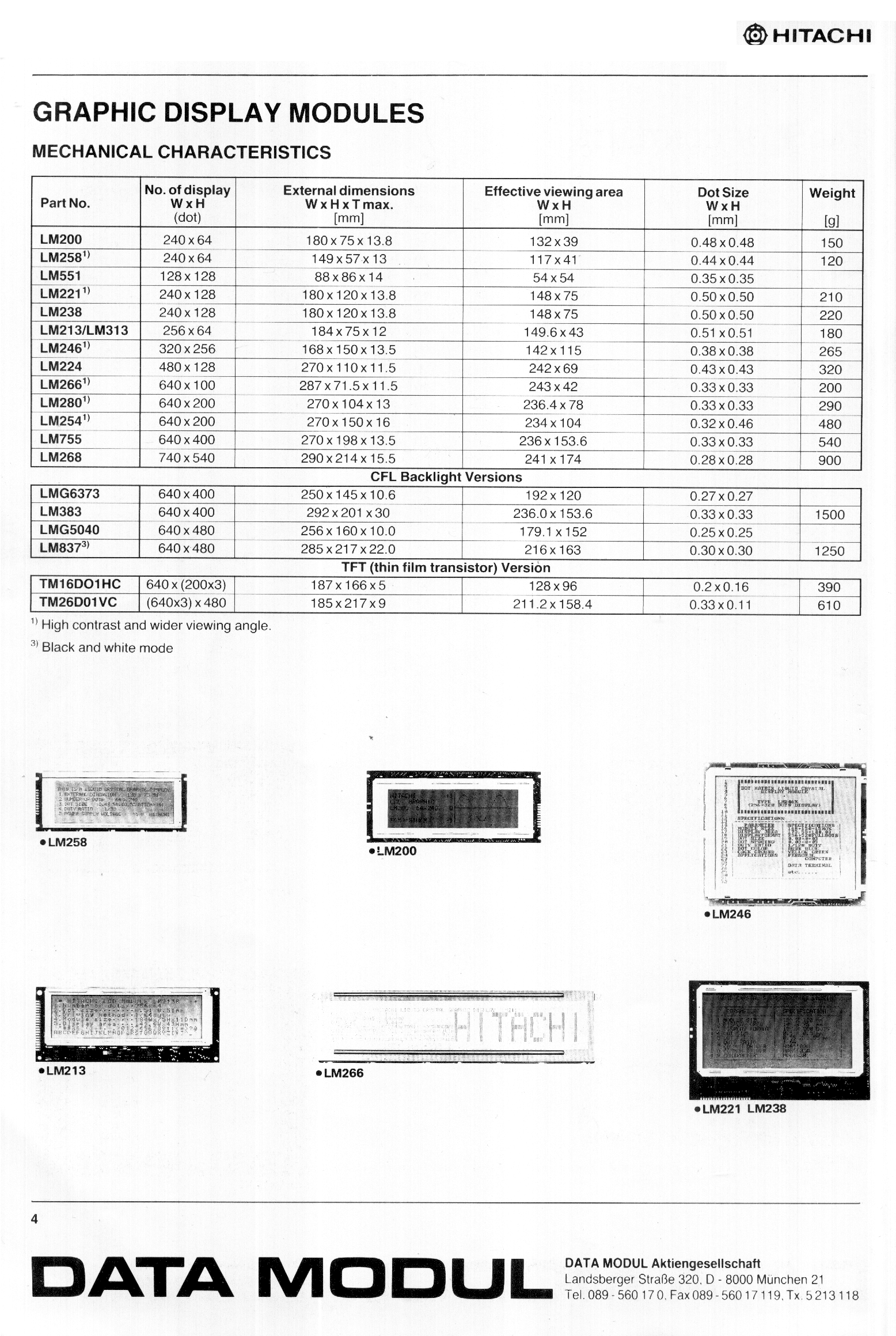
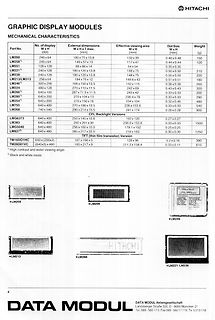
DISPLAY MODULES
MECHANICAL CHARACTERISTICS
Part No. No. of display W x H (dot) External dimensions W x H max. [mm] Effective viewing area W x H [mm] Dot Size W x H [mm] Weight [g]
LM200 240 x 64 180 x 75 x 13.5 132 x 39 0.48 x 0.38 150
LM258 240 x 64 149 x 57 x 13.5 117 x 41 0.44 x 0.44 120
LM551 128 x 128 88 x 86 x 14 54 x 54 0.35 x 0.35
LM221 240 x 128 180 x 120 x 13.8 148 x 75 0.50 x 0.50 210
LM213/LM313 240 x 128 180 x 120 x 13.8 148 x 75 0.50 x 0.50 220
LM246 320 x 256 270 x 198 x 13.5 142 x 115 0.51 x 0.38 265
LM266 480 x 128 270 x 110 x 11.5 242 x 69 0.34 x 0.33 320
LM280 640 x 200 270 x 140
0 V; T = −40 to +85 °C; unless otherwise specified. DD SS amb SYMBOL PARAMETER CONDITIONS MIN. TYP. MAX. UNIT Supplies V supply voltage 2.5 − 5.5 V DD DD supply current operating mode; no load;− 100 200 A V = V or V ; I DD SS fSCL= 400 kHz DD(stb) standby current standby mode; no load; − 2.5 10 A V I
den Nennvolumenstrom. Folgende Richtwerte sollten dabei nicht überschritten werden: dp = 120 Pa/m max von Rohrleitungen DN 10 bis DN 65 w max = 0,7 m/s von Rohrleitungen DN 80 bis DN 125 w max = 1,2 m/s ab Rohrleitungen DN 150 w = 2,0 m/s max Subject to change and error 20/327 Version 11/2021 Abb. 0.8
which has two extreme values along the hysteresis curve Bx,1− B x,2 B x,1− B x,2 µmin = min , and µ max = max . (5.58) H x,1Hx,2H x,1− H x,2 Hx,1,Hx,2H x,1− H x,2 Hereµ min andµ max aretheminimumandmaximumslopeofthehysteresischaracteristics. The inequality µmin ≤ µ ≤ µ max (5.59) is obvious, from which
TrueRMS DMM (PeakTech) ----------------------- U_netz = 235,5 V I_max = 1,9 A (150V*1,5A = 225W P_out) P_in = 447 W Energiekostenmessgerät zeigt an: 280 W / 0.82 cosφ Woher kommt die starke Diskrepanz? Einer von beiden lügt. Ich denke es ist das Energiekostenmessgerät
nicht-sinusförmigem AC damit noch keine Erfahrungen. Anderes billig-DMM ------------------ U_netz = 233 V I_max = 1,30 A (150V*1,5A = 225W P_out) P_in = 303 W Auh weih... welchem soll man glauben?
beseitigen. Heute weis man das natürlich alles. Terminierung ist das stichwort. Koax-Kabel eben kein RG213, sondern was 75-ohmiges ;). Für den VIDEO-Zweig kann man hier mal klauen (oben im Bild) https://media.elv.com/file/1997_05_14_verstaerker.pdf Oder hier (T7,T8,T9 und T10) https://media.elv.com/file
pragmatisch: Da Antennenkabel reichlich vorhanden ist, werde ich das einfach mal testen. Sind ja nur max 20m die ich damit überbrücken will.
” The minimum bootstrap capacitor value can be calculated from the following equation: 2 2 Q + Iqb(max)+Q +ls ICb( le)k ⎢ f f ⎥ C ≥ ⎣ ⎦ Vcc− V f− V LS−V Min where: Q g Gate charge of high-side FET f = frequency of operation ICbs (leak)ootstrap capacitor leakage current Iqbs (max)Maximum V BS quiescent
SUBPART J APPLICABLE AT THE DATE OF MANUFACTURE. COMPLY WITH DHHS RULE 21 CFR CAMBRIDGE, CB5 9PB. MAX WARNING: THIS APPLIANCE MUST BE EARTHED. Amplifier Board L924 Contents Circuit description Component overlay Parts list Circuit diagrams The line ‘NFB’ provides for a portion of the negative feedback
Max M. schrieb im Beitrag #7684883: > Also über 60kV kabel unter 10mm Durchmesser ist unrealistisch? Es gibt 60kV Kabel mit PE Isolation, hat um die 7-8mm. Man kann auch RG213 benutzen, das hält bis
Max M. schrieb im Beitrag #7684938: >> RG213 benutzen, das hält bis zu 70kV > > Also knallt bei bis zu 70kV, oder für bis zu 70kV Betreibsspannung > geeignet? Weiß ich nicht. > Belden 8866 ist
durch. Der verstopft und würgt ab. Auch dem nachbar sein sabo schafft das nicht. Laufen zu mager und max 2600 rpm. Wegen den umweltheinis. Beim aufsitzmäher den rpm-limiter rausnehmen. Ist eine blechlasche die den governor limitiert. Mit 3500 rpm gehen nasse 20cm problemlos. Beim schiebemäher die
Abstandhalter wiederfindet sehr gut. In dem Video: https://youtu.be/r_cnjIfncag?si=RtxUtHsBU4H_KeCV&t=213 ist aber auch direkt das Hitzeschild am Vergaser. Was ist nun richtig?
AAA Energizer Max (Singapore) AAA Energizer Max aus IR-FB gebr. MHD 12-2030 MHD 12-2030 Kauf 10-2020 Kauf 10-2020 17. Oktober 2021 15. Mai 2024 Entladung mit: 30 mA Entladung mit: 30 mA mAh max: 1197 mAh max: 1100 Time
. There are two cases that give a transition without Compare Match. OCR0A changes its value from MAX, like in Figure 15-7. When the OCR0A value is MAX the OCn pin value is the same as the result of a down-counting Compare Match. To ensure symmetry around BOTTOM the OCn value at MAX must correspond
Figure 20-10. Single-Slope Pulse Width Modulation Period (T) CMPn=BOTTOM CMPn=TOP "update" "match" MAX TOP CNT CMPn BOTTOM Output WOn The TCA.PER register defines the PWM resolution. The minimum resolution is 2 bits (TCA.PER=0x0003), and the maximum resolution is 16 bits (TCA.PER=MAX). The following
-Treiber-Elektronik die Sende-Stufe mit einer Art Tristate-Modus abschalten können. Beim bekannten MAX232 geht das leider nicht, dafür aber bei den Typen ICL3321 und MAX242. Tx: cmd arg0 arg1 ... argX/n Rx: cmd arg0 arg1 ... argX/n Beide verfügen über Low-Power-Shut- replyline1/n down-Modi, die sogar
Recommendations Profile Feature Pb-Free Assembly Tp Preheat / Soak: Tc-5 °C Temperature Min. (T ) 150 °C MAX. RAMP UP RATE = 3 °C/s p smin MAX. RAMP DOWN RATE = 6 °C/s Temperature Max. (T smax) 200 °C TL Time (s ) from (sminto Tsmax) 60~120 seconds Tsmax PREHEAT AREA L ) Ramp Up Rate (T tL T )p 3 °C / second
latched at the trigger to assist in point placement. There are three decimation modes: normal, min/max, and hires: H Normal (sub-sample) mode throws away samples between saved sample points. H Min/max mode saves the maximum and minimum samples over the decimation interval. H Hires mode gives extra resolution
Semiconductors Product specification NPN power transistors BD135; BD137; BD139 FEATURES PINNING • High current (max. 1.5 A) PIN DESCRIPTION • Low voltage (max. 80 V). 1 emitter 2 collector, connected to metal part of APPLICATIONS mounting surface 3 base • Driver stages in hi-fi amplifiers and television circuits.
TOM. There are two cases that give a transition without Compare Match. OCR0A changes its value from MAX, like in Figure 14-7. When the OCR0A value is MAX the OCn pin value is the same as the result of a down-counting Compare Match. To ensure symmetry around BOTTOM the OCn value at MAX must correspond
CHARACTERISTICS V = 12V, T = +25°C, unless otherwise noted. IN A Parameter Symbol Condition Min Typ Max Units Shutdown Supply Current VEN = 0V 0.3 3.0 µA Supply Current V = 2.0V, V = 1.0V 1.3 1.5 mA EN FB Feedback Voltage V FB 4.75V ≤ VIN≤ 23V 0.900 0.925 0.950 V Feedback Overvoltage Threshold 1.1 V Error
The maximum allowable continuous power dissipation at any ambient temperature is calculaDed by PTJ(MAX)- Lead Temperature ....................................260C TA/ JA. Exceeding the maximum allowable power dissipation Storage Temperature.............. –65°C to +150C will cause excessive die temperature
Feature Pb Free Solder Process Non-Pb Free Solder Process Average Ramp Up Rate (T to T ) 3°C / second Max. 3°C / Second Max. s p Preheat - Temperature Min (T sin.) 100°C 150°C - Temperature Max (T sax.) 150°C 200°C - Time (tsMin to s Max) 60 to 120 seconds 60 to 120 seconds Time Maintained Above Critical
PACKAGE OUTLINE TM DCP0038A PowerPAD TSSOP - 1.2 mm max height SCALE 2.000 SMALL OUTLINE PACKAGE C 6.6 TYP A 6.2 PIN 1 INDEX 0.1 C SEATING AREA 36X 0.5 PLANE 38 1 2X 9.8 9.6 9 NOTE 3 19 20 0.27 38X B 4.5 0.17 4.3 0.08 C A B SEE DETAIL A (0.15) TYP 2X 0.95 MAX NOTE 5 19 20 2X 0.95 MAX NOTE 5 0.25 GAGE PLANE 1.2 MAX 4.70 39 3.94 THERMAL PAD 0.75 0.15 0 -8 0.50 0.05 DETAIL A TYPICAL 1 38 2.90 2.43 4218816/A 10/2018 NOTES: PowerPAD is a trademark of Texas Instruments
color 0,0 pattern at Mode 15. several minor adjustment may be required. 2) Set External Bright to MAX position and Contrast to Adjustment should be following procedure and after MAX Position. warming up for a minimum of 10 minutes. 3) Select PRESET START → BIAS CAL command and Enter. • Alignment appliances

 Bild
Bild
 Bild
Bild
 Bild
Bild