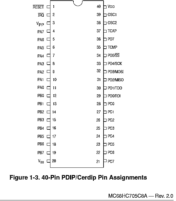
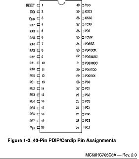
900ss schrieb im Beitrag #7925068: > Welche Werkzeuge hat du genutzt? Du hast das doch > kaum "zu Fuß" gemacht? Klar, nacharbeiten schon. Ja, alles zu Fuß. Der Instruction Set des 68HC05 ist super simpel
900ss schrieb im Beitrag #7925572: > Martin M. schrieb: >> Emulierst du dann eigentlich die Befehle des 68HC05 auf dem Cortex-M4? > > Im Eingangspost steht doch genau, was er gemacht hat. Also keine
https://www.amazon.de/s?k=gsm+schaltmodul&crid=PURTSBQ49JEO&sprefix=gsm+sch%2Caps%2C101&ref=nb_sb_ss_mvt-t11-ranker_1_7 Danke für den Tipp..den Artikel habe ich gesehen. Allerdings ist hier wieder das Problem das die Rufnummern vorher in eine Liste eingetragen werden müssen. Nur diese Rufnummern
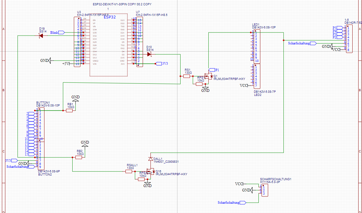
hartundweichware Am 12V Netzteil kommt ein 470uF Elko , an den verbraucher Schraubklemmen freilaufdioden SS34 (Schotky) und 100nF Kerko , Zwischen Drain und 12V eine TVS Diode SMBJ12A . Verbraucher haben 3A aber für zukünftige sollte es überdimensioniert bleiben. U.a. Membranpumpen als induktive Verbraucher
> > Am 12V Netzteil kommt ein 470uF Elko , an den > verbraucher Schraubklemmen freilaufdioden SS34 (Schotky) und 100nF Kerko > , Zwischen Drain und 12V eine TVS Diode SMBJ12A . > Verbraucher haben 3A aber für zukünftige sollte es überdimensioniert > bleiben. > U.a. Membranpumpen als induktive
ASEL_EMO2 10 DIO Pullup I2C Address Select. Address will 0X34/0X36 with the value of pin being "0' or "1" during de-assertion of reset. Can be programmed to be an output (as energy manager output for subwoofer) AVDD 9 P Analog supply (3.3 V) for PLL. AVDD_PWM 50
input or I/O pins is –0.5 V. During Overshoot Waveform voltage transitions, inputs may undershoot SS to –2.0 V for periods of up to 20 ns. SeeFigure 5. Maximum DC voltage on input and I/O pins is V CC + 0.5 V. During voltage transitions, input and I/O pins may overshoot to V + 2.0 V for periods up to
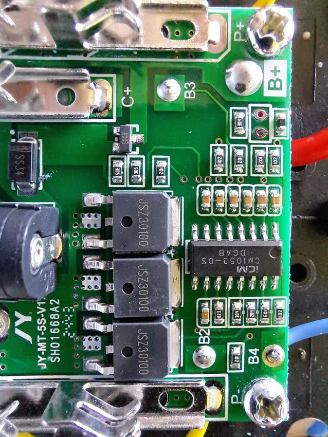
_____ > Wie repariere ich das am besten? Die defekte SS34 durch eine andere SS34 > ersetzen - oder alle drei Dioden durch 4A- oder 5A-Schottky ersetzen? Am besten drei neue, identische Schottkydioden nehmen – also aus einem Gurt, einer Charge; und keine
und haben demnach ungefähr > die gleiche Temperatur. Im besagten NT sitzen die drei SS34 ebenfalls ohne Zwischenraum nebeneinander. >> Wie repariere ich das am besten? Die defekte SS34 durch eine andere SS34 >> ersetzen - oder alle drei Dioden durch 4A- oder 5A-Schottky ersetzen?
value): start ---------------------------------------------------------- 3⋅CF ⋅ ( ( min||RSS )) The C SS capacitor is progressively charged until its voltage reaches the reference voltage (2V) and, consequently, the current through R SS goes to zero. This conventionally takes 5 time constants R SS ·CSS
( 60Hz) ( 2 Hz) (1Hz) (2Hz) n ÷ (5 x 3 x 2) ÷2 ÷2 ÷2 n 14 n OUT 4 n 2 10 VDD OUT 3 n n V WIDTH 1 4 SS 3 11 13 12 INHIBIT TEST OUT 2 OUT 1 OR RESET 13-17 Specifications ICM7213 Absolute Maximum Ratings Thermal Information Supply Voltage (DD - SS). . . . . . . . . . . . . . . . . . . .Thermal Resistance6.0V
/lapp/fuk2Jf1cPlV6EesaZZFavA~~&ved=2ahUKEwje4tGj66SNAxV8SvEDHSDqN9AQFnoECGEQAQ&usg=AOvVaw3uHpRXLOu2ss2TuR34-ikQ Diese Tabelle listet hingegen verschiedene Leitungsausführungen auf und es gibt wieder einen Verweis darauf, ob die Leitung an Haushaltsgeräten oder nicht verwendet wird. https://www.linzi.hu
January 1997 all IEC publications are issued with a designation in the 60000 series. For example, IEC 34-1 is now referred to as IEC 60034-1. Consolidated editions The IEC is now publishing consolidated versions of its publications. For example, edition numbers 1.0, 1.1 and 1.2 refer, respectively, to the
Wicklungen Bedeutung) 1000 - Widerstand der Wicklung in Ohm L3400 - Anzahl der \\'indungen um den Kern 34 0,12 - Drahtstärke (reiner Leitungsdurehme~ser ohne Isolierung) CuL - verwendetes Drahtmaterial (CuL - Kupfer mit Luekisolierung. CuPrL - Kupfer mit Perlonlackisolierung. WdSS - Widerstands. draht mit
0 76 6 MMBT3904100nF 0 V 6 u u C121 0 F 1 R1k 1 41 F 51 Y 1d 2 L10R135kR70 F C124 C 6 0 1 10k C u R34 O 1 a / d R20 nF10uF10uF/25V/0603 _ R1132 C37 0 0 X 5R BFu a 6C23 0n0nn2 n 5 R16 U3 2 k 1 1 T 0 e 102 / 100n1610 L C711 1n_060R17 1nR0003 0 J11 - 1 B C V 3331n_0603 30R220C33C35 1 33 _ V C73 5 1 41 0
AVR32: 4x schneller wegen 32bit 16x schneller wegen Mhz 3x schneller wegen IPC 10^80 => 265bit =>34byte Dementsprechend 34 add/adcs pro Zahl 382x das ganze, dazu noch overhead vom SRAM schreiben/lesen 34x382x z.B. 10cyclen Overhead für Read/Write =>130000 Zyklen für den 6502 oder ca. 1/10sec beim
Instruktionen in einem Takt ausführen, die der 6502 erst aus dem Speicher lesen muss. 384 Zahlen mit je 34 Bytes sind 13.056, das bekommt ein ATMega1284 komplett in seine 16kB RAM hinein.
screw-terminals for control/feedback inputs, supply power and motor connections. Drive Model Example SCA-SS Outline Drawing A B C Model Weight Length in (mm) Width in (mm) Height in (mm) oz (g) SCA-SS-70-10 7.09(180) 3.94(100) 1.57(40) 26.10(740) SCA-SS-70-30 7.87(200) 3.94(100) 3.15(80) 40.57(1150) ElectroCraft Brushed DC Motor with Tacho & Encoder SCA-SS-70-10 Power Supply ElectroCraft Servo Amplifier 12 - 70 VDC ElectroCraft Brushed DC Motor ElectroCraft Servo Amplifier 12 - 70 VDCy ElectroCraft DirectPower™, DirectPower™ Plus, EA-Series & SC-Series 34
SDA SCL SDAH SCLH SDA SCL (2) (2) (2) (2) (2) (2) (2) (2) MCS MCS (4) (4) (3) (3) VDD VDD V V V V SS SS SS SS SLAVE SLAVE MASTER/SLAVE MASTER/SLAVE msc612 (1) SDA and SCL are not used here but may be used for other functions. (2) To input filter. (3) Only the active master can enable its current-source
except when the device is in ‘Powersave’ mode when VBIASwill discharge to VSS. Should be decoupled to V SS by a capacitor mounted close to the device pins. 10 TXAN O/P The inverted output of the Tx Output Buffer. 11 TXA O/P The non-inverted output of the Tx Output Buffer. 12 VDD Power The positive supply
FE bit. When FE feature is enabled, RI rises on stop bit instead of the last data bit (See Figure 34 and Figure 35). 81 4164G–SCR–07/06 Figure 34. UART Timings in Mode 1 RXD D0 D1 D2 D3 D4 D5 D6 D7 Start Data Byte Stop Bit Bit RI SMOD0 = X FE SMOD0 = 1 Figure 35. UART Timings in Modes 2 and 3 RXD D0
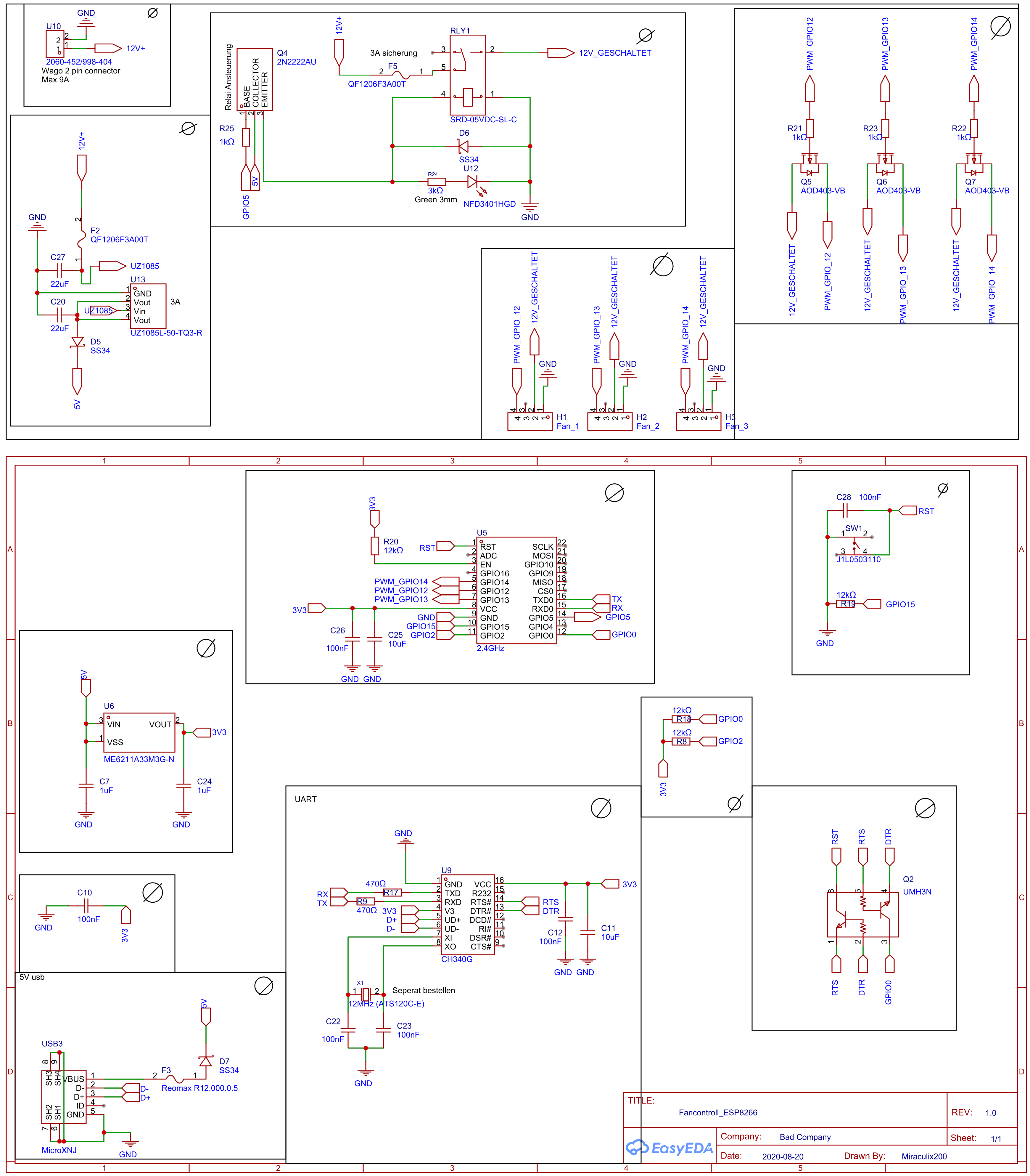
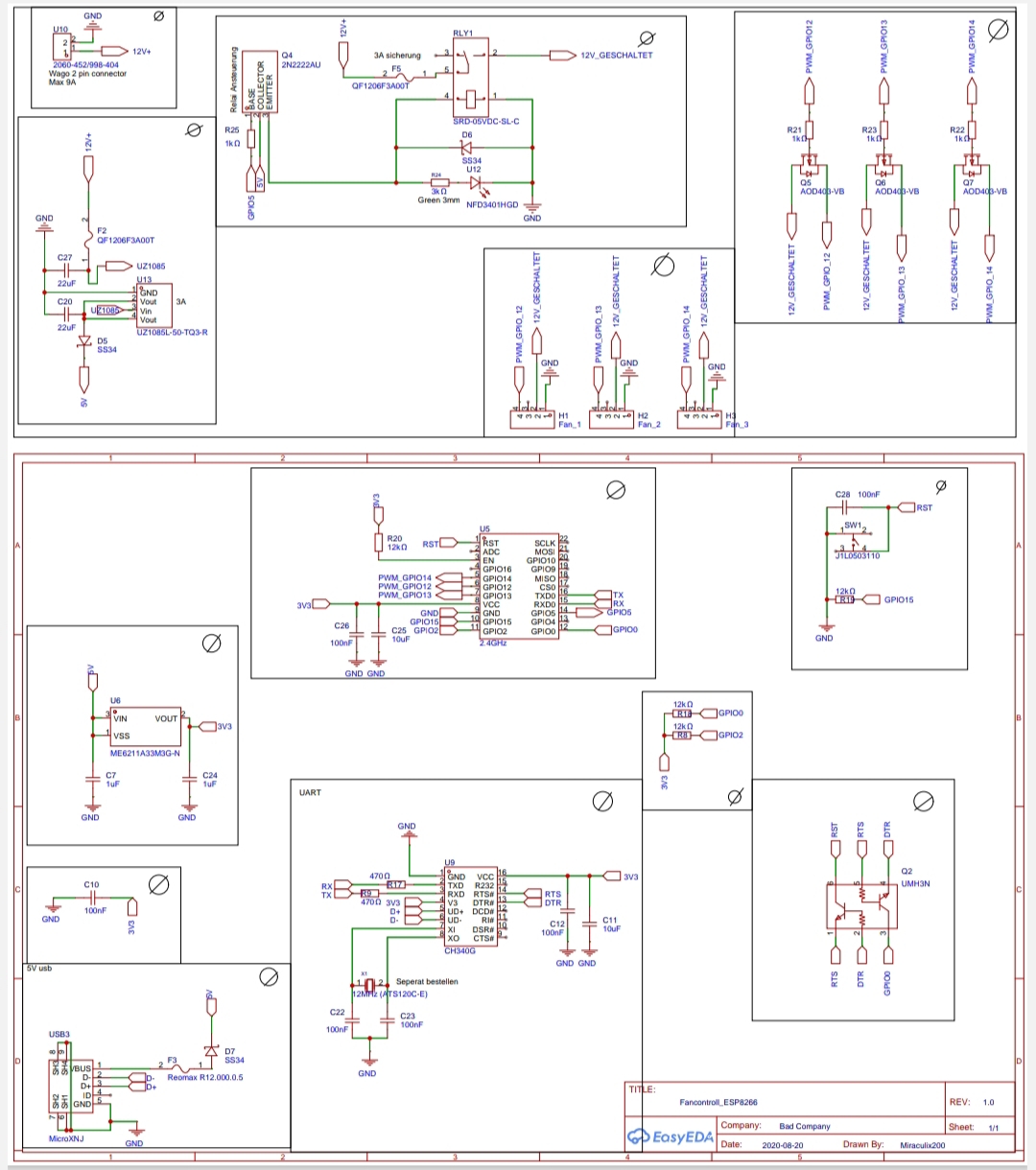
QF1206F3A00T l S L I 4 1 e B C E R 1 2 3 SRD-05VDC-SL-C R25 R21 R23 R22 V D6 1k▯' 1k▯' 1k▯' 2 1k▯' 1 SS34 U12 V R24 5 Q5 Q6 Q7 3k▯' AOD403-VB AOD403-VB AOD403-VB O Green 3mm NFD3401HGD P GND 2 G GND F2 QF1206F3A00T T T E T T C27 1 E T T T 1 L L UZ1085 L T T A _ H 3 H 4 A L L H I C _ C _ 22uF U13 H H H
QF1206F3A00T l S L I 4 1 e B C E R 1 2 3 SRD-05VDC-SL-C R25 R21 R23 R22 V D6 1k▯' 1k▯' 1k▯' 2 1k▯' 1 SS34 U12 V R24 5 Q5 Q6 Q7 3k▯' AOD403-VB AOD403-VB AOD403-VB O Green 3mm NFD3401HGD P GND 2 G GND F2 QF1206F3A00T T T E T T C27 1 E T T T 1 L L UZ1085 L T T A _ H 3 H 4 A L L H I C _ C _ 22uF U13 H H H
. Zu den Bauteilen. Auf der Rückseite ist nichts drauf. Der schon erwähnte Viereckige ist ein SM34F Die beiden 8 poligen sind einmal U11 54331 und U1 54335A Der 24polige am SD Slot U2 ist ein BY8001-24SS U8 ist ein DRV632 U9 ist ein PCM 1862 Hoffe das hilt weiter.
ist ein SM34F Bestimmt nicht. Ist das alles was dort drauf steht? Im Zweifelsfall muss der rausfliegen und durch etwas anderes ersetzt werden. Gruß Jobst
supply voltage 2.5 − 6.0 V I supply current operatingmode;V = 6 V; − 40 100 A DD DD no load; I = DD or SS; fSCL= 100 kHz stb standby current standby mode; VDD= 6 V; − 2.5 10 A no load; I = DD or SS VPOR Power-on reset voltage V DD= 6 V; no load; − 1.3 2.4 V V I= VDDor VSS note 1 Input SCL; input/output SDA
Filter 60Hz -64 550Hz 5V Frequency Response ¾ -4 ¾ dB Relative to 1700Hz @ 0dBm 2700Hz -3 3300Hz -34 Carrier Detect Sensitivity 5V ¾ -48 ¾ dBm tDOSC Oscillator Start Up Time 5V ¾ ¾ 2 ¾ ms tSUPD Power Up to FSK Signal Set Up Ti5V ¾ 15 ¾ ¾ ms tDAQ Carrier Detect Acquisition Time 5V ¾ ¾ 14 ¾ ms tDCH End

 Bild
Bild
 Bild
Bild
 Bild
Bild

 Bild
Bild

 Bild
Bild
 Bild
Bild
 Bild
Bild
 Bild
Bild
 Bild
Bild
 Bild
Bild