-
 Bild
Bild
Text über Webinar zu 0.5 mm Pitch PCB Design
UltraScale+™ FPGA. This $9 (USD) board 1 demonstrates measured performance of 1 Gb/s LVDS and 12.5 Gb/s high-speed transceivers on a low-cost PCB. AMD 0.5 mm pitch packages provide the lowest total solution cost of any AMD UltraScale+ device or Lattice FPGA. When combined with a low-cost PCB, you get lower
-
 Bild
Bild
Text über Webinar zu 0.5 mm Pitch PCB Design
UltraScale+™ FPGA. This $9 (USD) board 1 demonstrates measured performance of 1 Gb/s LVDS and 12.5 Gb/s high-speed transceivers on a low-cost PCB. AMD 0.5 mm pitch packages provide the lowest total solution cost of any AMD UltraScale+ device or Lattice FPGA. When combined with a low-cost PCB, you get lower
-
Artikel
Zahlensysteme
hexadezimale Schreibweise wird gerne verwendet um zwei Bytes zusammenzufassen: Bsp.: 0x010F => 01 ist das High Byte, 0F ist das Low Byte. Oktal. Oktalzahlen schreibt man in C mit einer führenden "0". C-Programmierer sollten sich die führende Null bei Oktalzahlen unbedingt merken, auch wenn sie keine Oktalzahlen
-
Thread
Verkaufe HP Hewlett Packard Agilent HP6624A 4 Kanal Netzteil
Hallo, ich möchte gern folgendes Netzteil abgeben: HP6624A Kanal 1&2 Low: 0-7V 0-5A or High 0-20V 0-2A Kanal 3&4 Low: 0-20V 0-2A or High 0-50V 0-0.8A OVP und OCP einstellbar Jeder Kanal kann als Downprogrammer ~110% seines Nennstroms als Senke, jedoch nur
-
Thread
Komparator Aufbau - diskret oder über µC?
Schwellspannung muss an 2 verschiedenen Stellen erfasst werden, sobald Schwellspannung erreicht -> HIGH Pegel, sobald unterschritten (unter Berücksichtigung der Hysterese) -> LOW Pegel Danke Euch
könnte man doch im Abstand von wenigen ms den Komparatorausgang jeweils abfragen und wenn Zustand HIGH klar dominiert, dann den Ergebnisausgang (im Test-Programm Pin 21 bzw.22) auf HIGH setzen und und ISR für ca. 5sec sperren (5sec ist etwa die Zeit,bei der ich sicher gehen kann, dass sich vom Prozess
-
Artikel
Avr-gcc Bugs
21621 Wrong / missing warning "skipping two-word instruction" 2.29.x 21849 Locate .progmemx.* at a higher address 2.29.x 21683 Support __gcc_isr pseudo-instruction 2.29 21583 Move .jumptables to a higher address 2.29 21569 Merge avr.sc and avrtiny.sc 2.29 21472 Add new emulation for ATtiny416 et al. (don't
Support ACCUMULATE_OUTGOING_ARGS 4.7.0 50775 Register allocator sets up frame and frame pointer with low register pressure 4.7.0, ra 50616 ICE: lto1.exe: invalid resolution in the resolution file 4.7.0, lto, mingw32 50566 Add support for better logging by means of -mlog= 4.7.0 50465 Use insn attribute
-
 Bild
Bild
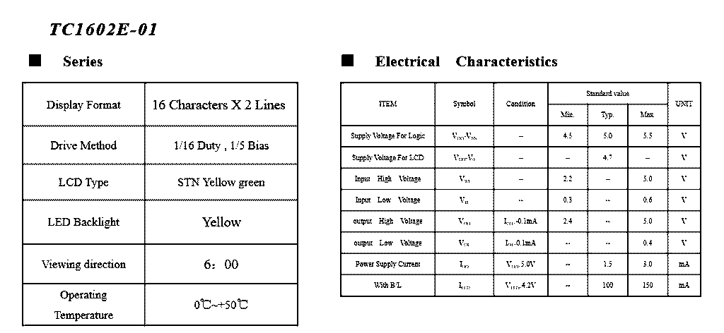
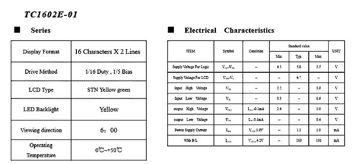
Datenblatt-Ausschnitt eines LCD-Displays TC1602E-01
UNIT Supply Voltage For Logic VDD-VSS - 4.5 5.0 5.5 V Supply Voltage For LCD VDD-VSS - 4.7 - V Input High Voltage VIN - 2.2 - 5.0 V Input Low Voltage VSS - 0.3 - 0.6 V Output High Voltage VOH Iout=0.1mA 2.4 - 5.0 V Output Low Voltage VOL Iout=0.1mA - - 0.4 V Power Supply Current IPD VDD-VSS 1.5 3.0 mA With
-
Thread
Lichtschranken-Rundenzähler (12V).
(L) and the high current through these tracks can generate high voltages up to VL = L * dI/dt. This spike voltage VL is most likely outside the specification of the RESET pin. By adding a series resistor between the switch and the capacitor, the peak currents generated will be significantly low and it will not be large enough to generate high voltages at the RESET pin. An example connection is shown in the following diagram. Figure 3-2. Switch Connection for Reset Pin..." /Zitat Quelle
-
Thread
Orange Pi Zero 4, NVIDIA investiert in MediaTek, MicroPython-Update und mehr
port for Infineon PSOC Edge microcontrollers. This is a bare-metal port using CMSIS 6 and a set of low-level HAL submodules from Infineon's Modus Toolbox. It uses the standard ARM toolchains and builds with make. It currently supports a UART REPL, a filesystem (using QSPI flash), machine Pin, UART and
the setup to the specific hardware: Radxa Dragon (Q6A & Q8B): Flashes directly to high-speed UFS storage, setting up the board’s custom UEFI boot environment. (Note: Users will need to enter the UEFI menu and set the boot order manually after flashing to boot from UFS). Arduino Qualcomm
-
Thread
XIAO Plus-Varianten, große Politik, CartoType mit LLM und anderes mehr
Die beiden folgenden Passagen verdienen besondere Aufmerksamkeit: [c] AI drives test intensity – Higher data rates, lower latency, and increasingly heterogeneous architectures are increasing testing, emulation, and interoperability requirements. Supply limits revenue – Keysight says demand is not
-
 Bild
Bild
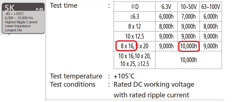
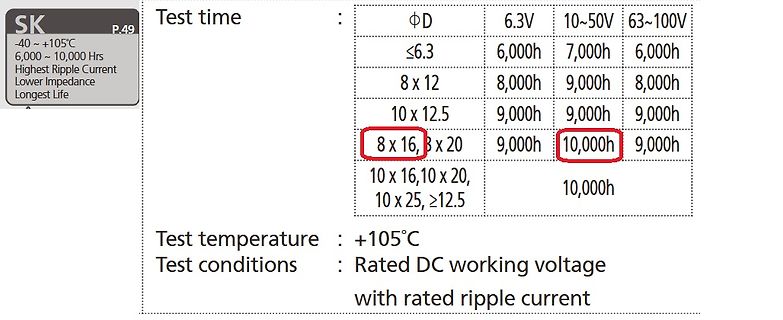
Tabellenausschnitt aus einem Datenblatt für Elektrolytkondensatoren
SK P.49 -40 ~ +105°C 6,000 ~ 10,000 Hrs Highest Ripple Current Lower Impedance Longest Life Test time : ΦD 6.3V 10~50V 63~100V ≤6.3 6,000h 7,000h 6,000h 8 x 12 8,000h 9,000h 8,000h 10 x 12.5 9,000h 9,000h 9,000h 8 x 16, 8 x 20 9,000h 10,000h 9,000h
-
Thread
Problem mit DCF77 Empfänger, Signal passt nicht
dcf-empfangsmodul-dcf-2.html Das Pollin-Modul (2013) PS Das passt .. das Modul sendet aber nur nach einem High/Low-Wechsel an Pon. [pre] || (Achtung Pon nicht offen lassen sonst kommt Mist an! || immer auf GND ziehen ) \/ -------- | x | +5V | x | GND
Zum Beispiel: .def flags = r11 ; Verschiedene Flags ; Bit 0: akueller DCF77-Zustand - high oder low ; Bit 1: vorheriger DCF77-Zustand ; Bit 2: Uhr wurde mind. einmal synchronisiert ; Bit 3: Start neue Minute;TimerISR set,main reset ; Bit 4: Datum gueltig
-
Thread
Schutzschaltung für einen MCU durch Anschluss an eine Powerbank
#8089452: > Thomas E. schrieb: >> Attiny84 > > Wie sind die Fuses gesetzt? [c] FUSES = { .low = 0xE2, // LOW {SUT_CKSEL=INTRCOSC_8MHZ_6CK_14CK_64MS_DEFAULT, CKOUT=CLEAR, CKDIV8=CLEAR} .high = 0xDF, // HIGH {BODLEVEL=DISABLED, EESAVE=CLEAR, WDTON=CLEAR, SPIEN=SET, DWEN=CLEAR, RSTDISBL=CLEAR
-
Thread
Programmer für INTEL D8751H gesucht
TU Student 1. schrieb im Beitrag #8088959: > /EA auf Low setzen, um Code aus dem externen EPROM auszuführen. Geht mit gesetztem Security-Bit nicht mehr.
>> /EA auf Low setzen, um Code aus dem externen EPROM auszuführen. > > Geht mit gesetztem Security-Bit nicht mehr. Das geht schon. 99% meiner '51er waren recycelte ROM-Versionen. Aber es geht nicht dynamisch
-
 Bild
Bild
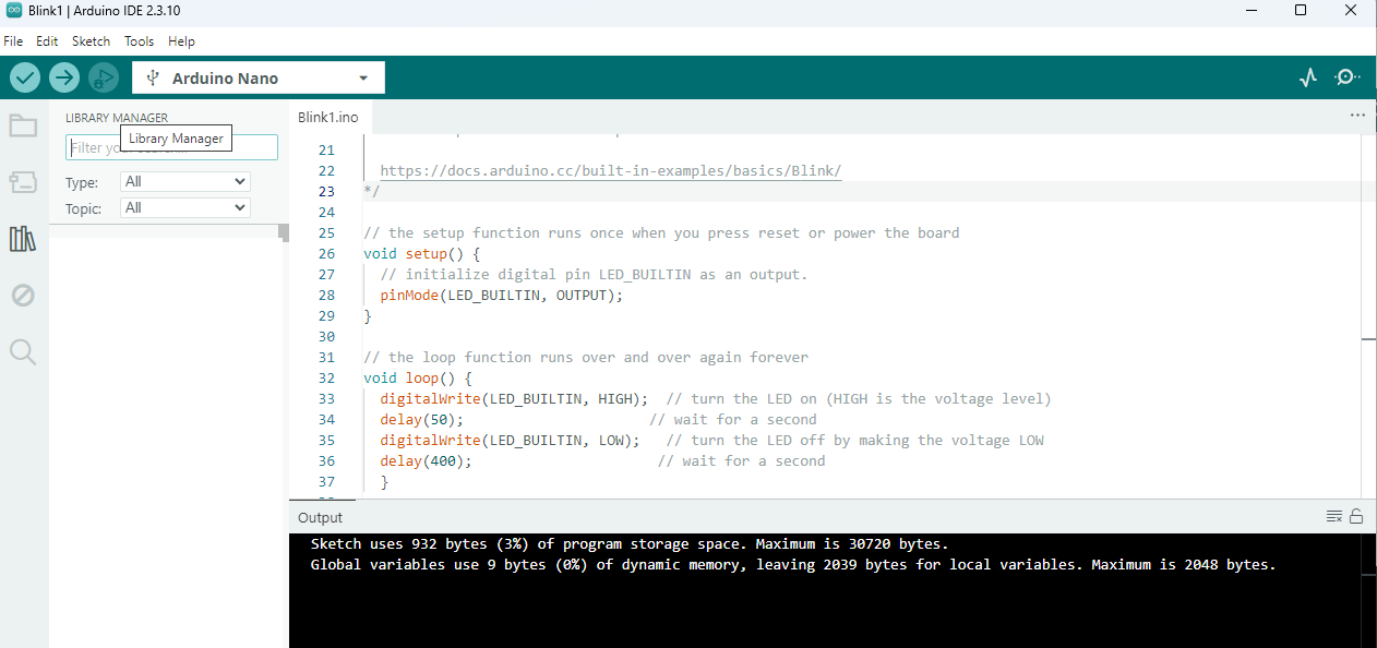
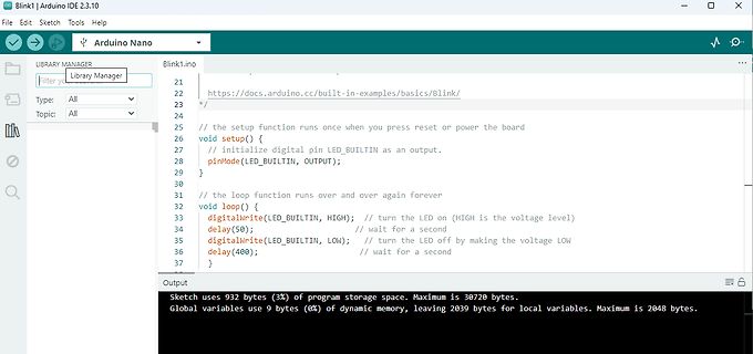
Arduino IDE Programmcode Blink1.ino
LED_BUILTIN as an output. pinMode(LED_BUILTIN, OUTPUT); } void loop() { digitalWrite(LED_BUILTIN, HIGH); delay(50); digitalWrite(LED_BUILTIN, LOW); delay(400); } Sketch uses 932 bytes (3%) of program storage space. Maximum is 30720 bytes. Global variables use 9 bytes (0%) of dynamic memory, leaving 2039
-
 Bild
Bild
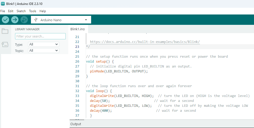
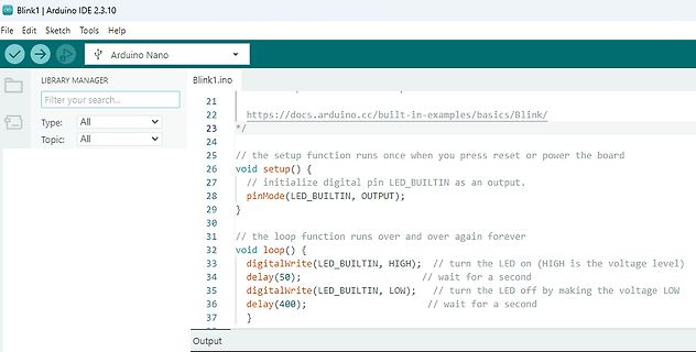
Arduino IDE Code für Blink-Beispiel
the loop function runs over and over again forever 31 void loop() { 32 digitalWrite(LED_BUILTIN, HIGH); // turn the LED on (HIGH is the voltage level) 33 delay(50); 34 digitalWrite(LED_BUILTIN, LOW); // turn the LED off by making the voltage LOW 35 delay(400); 36 } 37 Output
-
Artikel
Fehlersuche
Schaltung an? Liegen die richtigen Signale an den Zwischenpunkten der Schaltung an? Sind Logikpegel sauber LOW und HIGH? Wenn nein, dann sind oft mehrere Ausgänge gleichzeitig auf einem Bus aktiv und ziehen in verschiedene Richtungen (Low und High). Oder Die Ausgänge sind zu schwach, um die Lasten zu treiben
um Zeitverhalten von Software zu messen, z.B. Interruptroutinen. Zum Beginn setzt man ein Pin auf HIGH, am Ende auf LOW, das kann man dann sehr einfach mit einem Oszilloskop messen Ebenfalls kann man mit so einem Testpin den Anfang eines speziellen Programmablaufs signalisieren, um ein Oszilloskop zu
-
Thread
ESP 32 oder Nano
eines uC ist, dann Du jeden Pin dieser 5 Anschlüsse wahlweise zwischen einem ADC Eingang, einem GPIO Low, einem GPIO High oder einem GPIO Input Floating schalten kannst. Es macht aber eventuell Sinn, eine der Leitungen fest mit VRef des ADC zu beschalten und alle Spannungen gegen diese Leitung zu messen
) - Alle internen Quellen deaktivieren - Über die 100-kΩ-Pull-ups nacheinander jede Leitung auf High ziehen und den Pegel der anderen drei messen: - Isolierte, korrekt verdrahtete Sensoren zeigen keine Kopplung - **Kurzschluss zwischen zwei Adern** → beide Pegel identisch → Fehler lokalisiert
-
 Bild
Bild
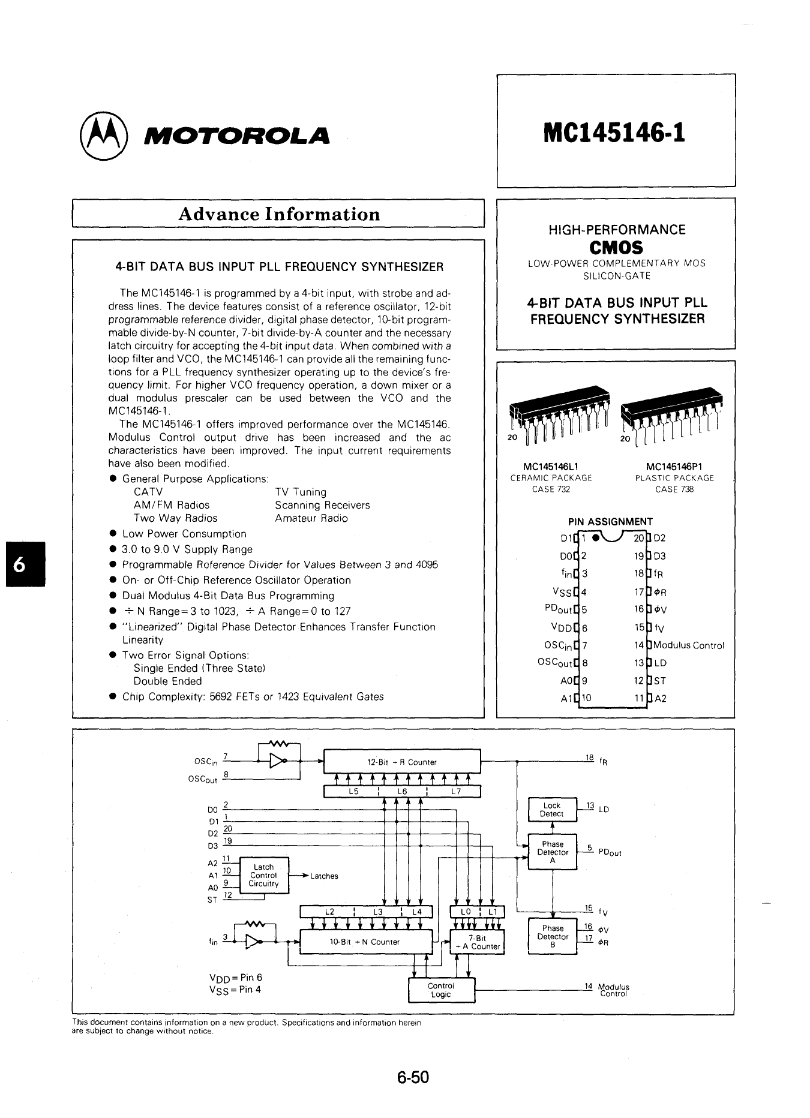
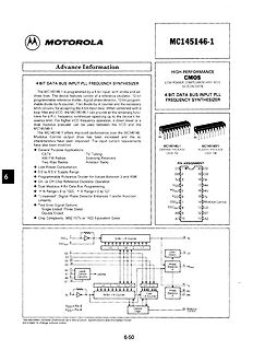
Datenblattseite des Motorola MC145146-1 Synthesizers
MOTOROLA MC145146-1 HIGH-PERFORMANCE CMOS LOW POWER COMPLEMENTARY MOS SILICON-GATE 4-BIT DATA BUS INPUT PLL FREQUENCY SYNTHESIZER MC145146L1 CERAMIC PACKAGE CASE TO42 MC145146P1 PLASTIC PACKAGE CASE TO138 OSC CL, VDD, VSS,
-
Thread
2 Geräte an einem µC UART
Empfänger für die Dauer des Firmware Updates zum schweigen bringen. Erste Idee: der GPS Sender wird low side mit einem ULN2003A abgeschaltet. Vcc bleibt drann. => kann das funktionieren? oder können da Pegel auftreten, welche der NEO-6M nicht so mag und ich einen Hardwareschaden riskiere? Zur Sicherheit
einen 74LVC2G125 und einen 74LVC2G126. Das sind zweifach-Buffer mit Enable beim 125 ist Enable Active-low, beim 126 ist Enable Active-High. Die Enables führst Du alle zusammen auf einen GPIO-Pin und kannst damit zwischen Update-UART und GPS-UART umschalten. fchk
-
Thread
NFC-Jukebox auf Basis einer bestehenden Bluetooth-Box
der vom Wemos gesteuert wird und den Verstärker + Boost-Wandler freischaltet. - Oder ein einzelner High-Side-Switch, der die komplette Last (5 V + Verstärker) steuert. Was wäre hier die sauberste und energieeffizienteste Lösung? Ich freue mich über Tipps zu: - geeigneten Verstärkern (klein, effizient
das Aufladen einfacher, DFPlayer geht bis ca. 3V runter, der ESP ist auch 3.3V, der PNY m.W. auch. Low-Drop-Regler von 4.2V…3.3V -> 3.3V könnte reichen, und wie weit unter 3.3V das noch funktioniert wäre zu testen, aber viel Kapazität geht "da unten" nicht verloren. Für den Verstärker: Wieviel Leistung
-
Thread
Claude Code trifft AVR-Assembler: vom Chip in den Browser mit einem Prompt
SINGLE.CMP0BUF = duty; } static void delay_sht(void) { _delay_us(20); } static void data_low(void) { PORTA.OUTCLR = SHT_DATA_bm; PORTA.DIRSET = SHT_DATA_bm; } static void data_release(void) { PORTA.DIRCLR = SHT_DATA_bm; } static uint8_t data_is_high(void) { return
= 0; mask >>= 1) { PORTA.OUTSET = SHT_SCK_bm; delay_sht(); if (data_is_high()) b |= mask; delay_sht(); PORTA.OUTCLR = SHT_SCK_bm; delay_sht(); } if (do_ack) { data_low(); delay_sht(); } PORTA.OUTSET
-
Thread
Sichere Ethernet-MCU, AI am Raspberry Pi, Lesestoff und mehr
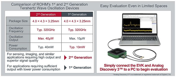
0.5mm chip size as the 1st Generation product while adopting an internal structure that enables higher output. As a result, output power has been increased to approximately 4 times that of the 1st Generation product, reaching a maximum of 40µW. The higher output power improves the detectability of THz
detection. ROHM will also continue sales of 1st Generation devices for applications that prioritize low power consumption. For further information, please contact a sales representative or visit url=https://www.rohm.com/contactus]the contact page[/url] on ROHM’s website. Purchase of the evaluation kit
-
 Bild
Bild
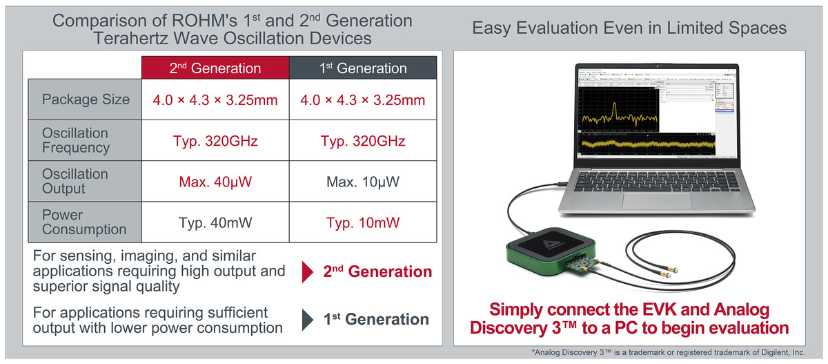
Vergleichstabelle und Produktfoto von Terahertz-Wellen-Oszillationsgeräten
10µW Power Consumption Typ. 40mW Typ. 10mW For sensing, imaging, and similar applications requiring high output and superior signal quality 2nd Generation For applications requiring sufficient output with lower power consumption 1st Generation Easy Evaluation Even in Limited Spaces Simply connect the EVK
-
Thread
Controller PLL TBB146
Kathode an den Zeileneingängen. Zusammen mit dem S187 ergab das dann 10 schaltbare Frequenzen. Für ein "high" am Teilereingang wurde die Diode "durchgebrannt" (Eingang offen), blieb sie intakt, ergab das "low".
-
Thread
Sporadischer digitaler Glitch beim Abspielen von Videos und Audio auf Laptop Vector GP76
Bei Multimediawiedergabe wirft Windows den "High-Precision Timer" an. Scheinbar ist die gelobte Gaminghardware dafür zu schlapp, oder falsch konfiguriert. Ein hülfreiches Programm zur Diagnose, misst die Zeiten, die ein: "Deferred Procedure
Audio-Codec von dem älteren Format MPEG-1 Layer II auf den modernen Standard AAC-LC (Advanced Audio Codec – Low Complexity)..." Einige Digital-Kabel-Radio-Geräte blieben entweder ganz stumm oder hatten Probleme mit dem Update. Es lief am Anfang nicht ganz rund. MER musste mindestens 31 dB sein und Pegel über
-
Thread
Adresierung USB-Hubs und Ports
When RS485 mode is enabled, inverts the RTS line from active-high (default) to active-low. rs485_rts_on_delay When RS485 mode is enabled, sets the delay (in milliseconds) between data transmission starting
-
Thread
Messtechnik, Drohnen und neue Mikrocontroller
under 1.2 W/cm2 laser irradiation - Tandem device embedded in UAV winglet powers a propeller under high-power laser [/c] ### Leicht recyclierbarer Zink-Ionen-Superkondensator. Neuigkeit Nummero zwei für „Freunde der Drohne“ ist ein Superkondensator, der einerseits „rigide“ ist, andererseits aber
architecture helps reduce conversion losses and is a major reason BG2B is designed to be Silicon Labs’ lowest-power Bluetooth LE SoC to date. With ~1.1 µA EM2 current (16 kB RAM retained), lower MCU active current, and very low Bluetooth LE transmit and receive currents, BG2B helps developers extend battery
-
Thread
Akkubeleuchtung (Gleichstrom) an Nabendynamo (Wechselstrom)?
Busch-Mueller-Ixon-IQ-Speed/205419 Der hat einiges an Elektronik in sich: 2 Beleuchtungsstufen High/Low, merkt sich den letzten Betriebszustand, "erschnüffelt", ob der Akku schwächelt und schaltet ggf. auf Low. ==> Unstete Versorgung aus einem Dynamo könnte ihn schon durcheinander bringen. Der alte
-
Thread
Ansteuerung? Trafo mit 6 N_KANAL_LSG_MOSFETs.
ist das man diese Figure 7. Inverter Mode Operation aus snva678b.pdf anwendet. Wobei man die High-Schalter für die entsp. Halbwelle einschaltet und dann die entsp. para. Low-Schalter taktet womit wohl die Schaltverluste auf zwei FETs verteilt werden. VG Fritz
-
Thread
Identifikation Modbus-Controller-IC auf Platine
Sinn ergeben würde es, wenn der _SWIM_-Pin sowohl mit _nRE_ als auch _DE_ verbunden wäre: Ist _SWIM_ high, werden Daten empfangen, ist _SWIM_ low, werden Daten gesendet. Warum? Die einzige Alternative wäre _NRST_, und das ist einer der Standardpins des Controllers, der als Reset-Eingang verwendet wird.
-
Thread
MicroPython-Updates, Abschaltung von 2G-Netzen, BaoChip und AI-Software
ve encountered the opposite. There’s more process than ever: purchase orders take weeks, fees are higher, service quality has declined, and shipping times are slower. Crowd Supply also takes the largest cut of any vendor in the supply chain – 46% of the cash raised went to them. It sickens me a little
exposure to harsh blue light. According to Philips Evnia, the monitors also incorporate a dynamic low blue light system that divides the display into 48 zones, enabling segmented scanning and gradient tuning to minimise potentially harmful blue light while maintaining colour accuracy. [/c] ###
-
Thread
Thermisches Management für MOSFETs
eigentliche Problem / die philosophische Frage: Ich habe ein Board entworfen mit ISZ0702NLSATMA1 als (High- und Low-Side-)MOSFET. Der ISZ0702NLSATMA1 ist ziemlich klein, soll aber bis zu 86 A können (bei entsprechender thermischer Anbindung). Ich wundere mich etwas, da bei den MOSFETS das Drain-Pad gleichzeitig
Problem hat Infineon auch erkannt und deswegen das Source-Down-Package entwickelt. Du kannst für den High-Side-Schalter einen Drain-Down verwenden und für den Low-Side einen Source-Down, damit wird das Problem elegant umgangen. Dafür käme beispielsweise der hier infrage https://www.infineon.com/part/IQE030N06NM5
-
Artikel
WordClock mit WS2812
Nachbar-Pin ("0") angebracht werden. Beim Nucleo-Board wird der Pin BOOT0 bereits per 10k Pulldown auf Low-Pegel gezogen. Hier kann der ESP-Pin GPIO16 (ab Version 2.6.0: GPIO4) direkt ohne zusätzlichen Pulldown an BOOT0 angeschlossen werden. Zu beachten ist hier lediglich, dass kein Jumper auf Pin5-7 von
Anzeige-Logik und des MCURSES-Monitors auf dsp.c und monitor.c Aufteilung der ESP8266-Routinen auf esp8266.c (low-level) und timeserver.c (high-level) Diverse Optimierungen - u.a. durch Einsatz von uint_fast8_t Diverse Bugfixes STM32 Version 0.7.1. Portierung der Software auf STM32F411RE Nucleo-Board STM32 Version