-
Datei
Temperatur_DS18B20.ino
/** * Temperature monitor for DS18B20 (Dallas) or similar one (like DS18S20) * supported 1 until 4 sonsors (more is possible by changing code-lines) * target: ESP8266, especially Kit-8 type * written by Peter Rebesky, February 2023 * Copyright
in „ESP Temperaturmodul mit DS18B20 und Web-Ansicht“ · Mikrocontroller und Digitale Elektronik ·
-
PDF
Si_4421__RFM12B_.pdf
and set. 8. Synchron Pattern Command Bit 15 14 13 12 11 10 9 8 7 6 5 4 3 2 1 0 POR 1 1 0 0 1 1 1 0 b7 b6 b5 b4 b3 b2 b1 b0 CED4h The Byte0 of the synchron pattern (see FIFO and Reset Mode command, page 20) can be reprogrammed by B <b7:b0>. 9. Receiver FIFO Read Command Bit 15 14 13 12 11 10 9 8 7 6
in „RFM12b ideale Konfiguration“ · Mikrocontroller und Digitale Elektronik ·
-
PDF
RF12B_programming_guide.PDF
Configuration Setting Command bit 15 14 13 12 11 10 9 8 7 6 5 4 3 2 1 0 POR 1 0 0 0 0 0 0 0 el ef b1 b0 x3 x2 x1 x0 8008h e l: Enable TX register e f: Enable RX FIFO buffer Tel: +86-755-8297380Fax: +86-755-829735E-mail: sales@hoperf.com 1 http://www.hoperf.com RF12B V1.2 b1..b0: select band B1 b0 band
in „RFM12b ideale Konfiguration“ · Mikrocontroller und Digitale Elektronik ·
-
PDF
0900766b8139d711.pdf
. All devices, equipment and machinery must be electrically grounded. t Package Dimensions g h r i b g i n K Notes: 3. Lead spacing is measured where the leads emerge from the package. 4. The specifications, characteristics and technical data described in the datasheet are subject to change without
in „Deratingkurve einer Leuchtdiode“ · Analoge Elektronik und Schaltungstechnik ·
-
PDF
ZXMN2B01F.pdf
D Ordering information G Device Reel size Tape width Quantity per reel (inches) (mm) Top view ZXMN2B01FTA 7 8 3,000 Device marking 2B1 Issue 2 - March 2007 1 www.zetex.com © Zetex Semiconductors plc 2007 ZXMN2B01F Absolute maximum ratings Parameter Symbol Limit Unit Drain-source voltage VDSS 20 V Gate-source voltage VGS ±8 V (b) Continuous drain current @ V GS= 4.5V;amb=25°C ID 2.4 A (b) @ V GS= 4.5V;amb=70°C 1.9 A @ V GS= 4.5V;amb=25°C (a) 2.1 A Pulsed drain current) DM 11.8 A (b) Continuous source current (body diode) IS
in „LED-Spannungswandler mit MOSFET ?“ · Mikrocontroller und Digitale Elektronik ·
-
PDF
Datenblatt_DS18B20.pdf
+T&R -55°C to +125°C 3 TO-92 (2000 Piece) 18B20 DS18B20-SL/T&R -55°C to +125°C 3 TO-92 (2000 Piece)* 18B20 DS18B20-SL+T&R -55°C to +125°C 3 TO-92 (2000 Piece)* 18B20 DS18B20U -55°C to +125°C 8 μSOP 18B20 DS18B20U+ -55°C to +125°C 8 μSOP 18B20 DS18B20U/T&R -55°C to +125°C 8 μSOP (3000 Piece) 18B20 DS18B20U+T&R -55°C to +125°C 8 μSOP (3000 Piece) 18B20 DS18B20Z -55°C to +125°C 8 SO DS18B20 DS18B20Z+ -55°C to +125°C 8 SO DS18B20 DS18B20Z/T&R -55°C to +125°C 8 SO (2500 Piece) DS18B20 DS18B20Z+T
in „DS18B20 Darstellung von negativen Zahlen im Zweierkomplement?“ · Mikrocontroller und Digitale Elektronik ·
-
PDF
0900766b80091f12.pdf
durch KONTAKT LR nicht beschädigt werden. Bei lösemittelempfindlichen Kunststoffoberflächen wie z.B. Polystyrol und Polycarbonat ist vor der Anwendung von KONTAKT LR die Verträglichkeit zu prüfen. Da KONTAKT LR leichtentzündliche Lösungsmittel enthält, müssen bei der Anwendung Zündquellen ferngehalten
in „Erfahrungen mit Ozongenerator um Geräte zu "entmüffeln"“ · Mechanik, Gehäuse, Werkzeug ·
-
PDF
dB_Rhode_u__Schwarz.pdf
1 A bzw. 1 µA. Die dazugehörigen Bezeichnungen sind dB (W), dB (V), d2)(µV), dB (A) und dB (µA) sowie bei Feldstärkemessungen dB (W/m , dB (V/m), dB (µV/m), dB (A/m) und dB (µA/m). Ähnlich wie für dBm findet man auch hierfür die nach Norm eigentlich nicht
in „Spannungsverstärkung und dB“ · Analoge Elektronik und Schaltungstechnik ·
-
PDF
22b_fv_integramotor_brochure.pdf
quadrature encoder, and fault signal. Open loop. Literature P/N 07401072.A. TABLE 1: MOTOR SPECIFICATIONS 22B2BEBL/FV 22B3BEBL/FV 22B4BEBL/FV Continuous Stall Torque oz-in 25 36 50 Peak Stall Torque oz-in 35 50 75 Thermal Resistance °C/W 3.14 2.83 2.31 Torque Constant oz-in/A 8.4 8.9 9.0 Voltage Constant V/kRPM
in „Wie bekomme ich diesen Motor zum Drehen“ · Analoge Elektronik und Schaltungstechnik ·
-
PDF
Keysight_E5061B_VNA.pdf
Specification Typical Dynamic accuracy magnitude (0 dB attenuation, 50 Ω) ± 0.303 dB at –5 dBm ± 0.09 dB at –15 dBm ± 0.056 dB at –25 dBm ± 0.073 dB at –35 dBm ± 0.087 dB at –45 dBm ± 0.103 dB at –55 dBm ± 0.121 dB at –65 dBm ± 0.15 dB at –75 dBm ± 0.211 dB at –85 dBm ± 0.371 dB at –95 dBm ± 0.841 dB at –105 dBm ± 2.141 dB at –115 dBm Dynamic accuracy phase (0 dB attenuation, 50 Ω) ± 2.04 ° at –5 dBm ± 5 ° ± 0.6 ° at –15 dBm (+15 dBm, 20 dB ± 0.37 ° at
in „Genauigkeit eines Netzwerkanalysators“ · Mikrocontroller und Digitale Elektronik ·
-
PDF
O37577b_V02.pdf
und lesen Sie den gemessenen Ladestrom ab. Daten-Quelle: Braun ICS online Seite 1 von 3 ID: O37577b_V02.doc Braun GmbH Service Dokumentation Service Information OC 3 757 Mindest-Ladestrom: Der Mindestladestrom beträgt ILadestr≥ 51mA. Sollte der Messwert unter 51mA liegen, dann muss das Ladeteil ersetzt
in „Rasierer will Akku nicht laden“ · Analoge Elektronik und Schaltungstechnik ·
-
PDF
Datenblatt_DS18B20.pdf
+T&R -55°C to +125°C 3 TO-92 (2000 Piece) 18B20 DS18B20-SL/T&R -55°C to +125°C 3 TO-92 (2000 Piece)* 18B20 DS18B20-SL+T&R -55°C to +125°C 3 TO-92 (2000 Piece)* 18B20 DS18B20U -55°C to +125°C 8 μSOP 18B20 DS18B20U+ -55°C to +125°C 8 μSOP 18B20 DS18B20U/T&R -55°C to +125°C 8 μSOP (3000 Piece) 18B20 DS18B20U+T&R -55°C to +125°C 8 μSOP (3000 Piece) 18B20 DS18B20Z -55°C to +125°C 8 SO DS18B20 DS18B20Z+ -55°C to +125°C 8 SO DS18B20 DS18B20Z/T&R -55°C to +125°C 8 SO (2500 Piece) DS18B20 DS18B20Z+T
in „Timing Probleme 1-Wire“ · Mikrocontroller und Digitale Elektronik ·
-
PDF
Datasheet_TPIC6B595.pdf
Product Sample & Technical Tools & Support & Folder Buy Documents Software Community TPIC6B595 SLIS032B –JULY 1995–REVISED JUNE 2015 TPIC 6B 595Pow erLogic8-B itShiftR egister 1 Features The storage register transfers data to the output buffer when shift-register clear (SRCLR) is high. • Low
in „Interne Schaltung: TPIC6B595“ · Mikrocontroller und Digitale Elektronik ·
-
PDF
mc14553b-d-1192980.pdf
MR OVERFLOW (ACTIVE LOW) (ACTIVE HIGH) Figure 4. Expanded Block Diagram http://onsemi.com 5 MC14553B 0 2 3 5 4 9 1 1 1 1 1 1 4 3 1 a b c d e f g A B . 1 3 S C C O D 2 5 M 2 1 R D M 3 M 3 1 1 D A B C D P h L B I 3 0 1 5 3 2 4 6 1 7 5 Q 1 1 9 E M Q 7 D 1 L 2 D L ) Q 6 V T NT 3 E M K S Q R G C D 5 U S 2 D C E 1 1 V O P E m R 0 S <1 A a P p I ( D 1 . F 0 μ 4 3 1 A B F C C O S D 2 R S 3 M D 1 9 1 1 1 1 1 1 1 S a b c d e f g 3 D 1 B 5 0 4 1 Q 9 4 S M 1 C L Q 7 M 0 L 2 A B C D Ph L B 1 Q 6 5 3 2 4 6 1 7 K 3 C D Q 5 1 1 E T D B S V R E C U S R L I C Figure 5. Six−Digit
in „MC14553BCP - Alternative“ · Analoge Elektronik und Schaltungstechnik ·
-
PDF
0900766b8164cbe1.pdf
Wavelength(nm), onleads onleads Iv(mcd) at20mA 2θ1/2Deg)[4] Typ[3] (PackagedrawingA) (PackagedrawingB) Min Max 15° Amber 590 HLMP-EL1A-Z1Kxx HLMP-EL1B-Z1Kxx 12000 21000 HLMP-EL1A-Z1LDD HLMP-EL1B-Z1LDD 12000 21000 Red 626 HLMP-EG1A-Z10xx HLMP-EG1B-Z10DD 12000 21000 Red Orange 615 HLMP-EH1A-Z10DD HLMP-EH1B-Z10DD
in „Wer kennt sich mit UV aus? (LED Panel zur Photosynthese)“ · Analoge Elektronik und Schaltungstechnik ·
-
PDF
-
PDF
WS2812B_Datasheet_2017.pdf
WS2812B Intelligent control LED integrated light source Features and Benefits The control circuit and the LED share the only power source. Control circuit and RGB chip are integrated in a package of 5050
in „WS2812 Ansteuerung“ · Mikrocontroller und Digitale Elektronik ·
-
PDF
NCP81151B-D-931445.pdf
NCP81151B VR12.5 Compatible Synchronous Buck MOSFET Driver The NCP81151B is a high performance dual MOSFET gate driver optimized to drive the gates of both high−side and low−side power www.onsemi.com MOSFETs in
in „Push-Pull-Ausgang der alles kann :)“ · Mikrocontroller und Digitale Elektronik ·
-
PDF
B50_Rev1.1.pdf
t Q1 7 C B k L BD139-V 2 4 3 l 2 X B / - BC640 IC1 6 8 2 µ 1 t R T3 A 0 C 0 7 2 2 B 7 1 2 1 8 T 4 Z R KK1 1 S 2 1 X 5W 10 SK104-PAD M A 208 R13 9 k 1 B 2 R D 1 1 X S R M A 2 B T R18 208 R17 208 S 0,15 5W 0,15 5W 1 M T5 T4 E B C E B C 10k 2N3055ST 2N3055ST R15 i o 5 t B l - t
in „Labornetzteil - Schaltplan gesucht.“ · Analoge Elektronik und Schaltungstechnik ·
-
PDF
B50_Rev1.1.pdf
t Q1 7 C B k L BD139-V 2 4 3 l 2 X B / - BC640 IC1 6 8 2 µ 1 t R T3 A 0 C 0 7 2 2 B 7 1 2 1 8 T 4 Z R KK1 1 S 2 1 X 5W 10 SK104-PAD M A 208 R13 9 k 1 B 2 R D 1 1 X S R M A 2 B T R18 208 R17 208 S 0,15 5W 0,15 5W 1 M T5 T4 E B C E B C 10k 2N3055ST 2N3055ST R15 i o 5 t B l - t
in „Problem mit Bausatz Labornetzteil 30V / 3A“ · Analoge Elektronik und Schaltungstechnik ·
-
PDF
A-B-TIMING-CKT_11.pdf
A-B-TIMING-CKT_11.pdf
in „Brauche Hilfe bei Reperatur Oszilloskop Goldstar OS3020“ · Analoge Elektronik und Schaltungstechnik ·
-
PDF
EVEQDBRL416B_V2.pdf
mm (not to scale) EVEP AN?ApJ C=JA =HA= %. # # . $ +& & . # .# + & . ):2KJpKJ IECn=l ) - B , ) +2M. * - *:2KJpKJ IECn=l * B !. + . # P.9.* pEAH?EnC pl=n. B .% + . # 6olAH=n?A:– . B . + . # 8EAM BHom moKnJEnC IE@A . P.9.* JDE?FnAII J= .$ $.$.– . # + . . "-B .' + . . $ # # ! ! +AnJAH oB ID=BJ . ' ¡ 5MEJ?D ?EH?KEJ @E=CH=m. 5.P.5.6 ' B .&#+ . # . . ' % - , , )2M.* - IKHB=?AC P .#N"= #-B . + . n Phase Difference n Test Circuit Diagram ,AJAnJ IJA=@O poEnJ # 8 @? k k O.. k k 5ECn=F ) O2 5ECn=l ) 5ECn=l * ) * 6! 6" 6# 6$ O.. . µ. . µ.
in „Drehencoder bullet proof und einfach“ · Projekte & Code ·
-
PDF
00000132-530S_B_-Catalog.pdf
POLYPROPYLENE FILM CAPACITOR Series 530S PERFORMANCE CHARACTERISTICS Dielectric : polypropylene film Rated Voltage : 50/100Vdc, 200/250Vdc, 400Vdc, 630Vdc Capacitance range : 0.001 ㎌ to 0.22 ㎌ Capacitance tolerance : ±5 % ( J ), ±10 % ( K ), ±20 % ( M ) Operation Temperature range : - 40 ℃ to + 85℃ Insulation Resistance : minimum 30,000 ㏁, after 100Vdc 1 minute ( at room temperature ) Dissipation Factor : maximum 0.1% 1KHz at 25℃ Dielectric Withstanding Voltage : 250% of rated voltage, 2 seconds ( between terminations ) Protection : coated flame retardant epoxy resin DIMENSION ( standard ) unit
in „Kondensator Identifikation“ · Analoge Elektronik und Schaltungstechnik ·
-
PDF
0900766b814073e8.pdf
2. Soldering the headers ™ Before using your click board, make sure to solder 1x8 male headers to both left and right side of the board. Two 1x8 male headers are included with the board in the package. 1 Alcohol click 2 3 4. Essential features 1. Introduction Alcohol click can detect alcohol gas leves in concentrations from 0.04 to 4mg/l. The MQ-3 alcohol sensor has a sensor layer made of Tin dioxide (SnO2), an inorganic compound which has lower conductivity in clean air. The conductivity increases as Turn the board upside down so that Turn the board upward again. Make sure the levels of alcohol
in „Alkoholmessgerät programmieren“ · Mikrocontroller und Digitale Elektronik ·
-
PDF
BTA41-600B-1382474.pdf
Ordering information Table 3. Ordering information Type number Package Name Description Version BTA41-600B IITO3P plastic single-ended through-hole package; isolated heatsink SOT1292 mounted; 1 mounting hole; 3-lead TO3P 7. Marking Table 4. Marking codes Type number Marking codes BTA41-600B BTA41-600B © BTA41-600B All information provided in this document is subject WeEn Semiconductors Co., Ltd. 2017. All rights reserved Product data sheet 10 July 2017 2 / 12 WeEn Semiconductors BTA41-600B 4Q Triac 8. Limiting
in „Triac BTA41600B defekt nach durchgansprüfung“ · Mikrocontroller und Digitale Elektronik ·
-
PDF
BTA316B-600C.pdf
Ordering information Table 3. Ordering information Type number Package Name Description Version BTA316B-600C D2PAK plastic single-ended surface-mounted package (D2PAK); 3 leads SOT404 (one lead cropped) BTA316B-600C All information provided in this document is s© NXP Semiconductors N.V. 2014. All rights
in „Gibt es einen Triac der zwischen zwei Ausgängen wechseln kann?“ · Analoge Elektronik und Schaltungstechnik ·
-
PDF
IS42S16160B.pdf
organized as follows. Internal bank for hiding row access/precharge Power supply VDD VDDQ IS42S83200B IS42S16160B IS42S83200B 3.3V 3.3V 8M x 8 x 4 Banks 4M x16x4 Banks IS42S16160B 3.3V 3.3V 54-pinTSOPII 54-pinTSOPII LVTTL interface 54-ballBGA Programmable burst length – (1, 2, 4, 8, full page) Programmable
in „Fragen zu SDRAM“ · Mikrocontroller und Digitale Elektronik ·
-
PDF
Datenblatt_DS18B20.pdf
+T&R -55°C to +125°C 3 TO-92 (2000 Piece) 18B20 DS18B20-SL/T&R -55°C to +125°C 3 TO-92 (2000 Piece)* 18B20 DS18B20-SL+T&R -55°C to +125°C 3 TO-92 (2000 Piece)* 18B20 DS18B20U -55°C to +125°C 8 μSOP 18B20 DS18B20U+ -55°C to +125°C 8 μSOP 18B20 DS18B20U/T&R -55°C to +125°C 8 μSOP (3000 Piece) 18B20 DS18B20U+T&R -55°C to +125°C 8 μSOP (3000 Piece) 18B20 DS18B20Z -55°C to +125°C 8 SO DS18B20 DS18B20Z+ -55°C to +125°C 8 SO DS18B20 DS18B20Z/T&R -55°C to +125°C 8 SO (2500 Piece) DS18B20 DS18B20Z+T
in „1-Wire Protokollablauf“ · Mikrocontroller und Digitale Elektronik ·
-
PDF
EW162B0YLY.pdf
TECHNOLOGIES CORPORATION TOTAL PAGE VERSION : 4 CUSTOMER A CCEPTANCE SPECIFICATIONS MODEL NO. : 162B0(LED TYPES) FOR MESSRS : CUSTOMER'S APPROVAL DATE : _____________________________ BY : _____________________________ E M E R G I N G D I S P L A Y MODEL NO. VERSION TECHNOLOGIES CORPORATION 162B0(LED
in „Probleme bei 16x2 LCD mit KS0066 (EW162B0YLY)“ · Mikrocontroller und Digitale Elektronik ·
-
PDF
RF12B-IC-2.pdf
RF12B V1.1 RF12B Universal ISM Band FSK Transceiver DESCRIPTION RF12B Hope’s RF12B is a single chip, low power, multi-channel FSK transceiver designed for use in applications requiring FCC or ETSI conformance
in „Funk SI4420 kein Empfang“ · Mikrocontroller und Digitale Elektronik ·
-
PDF
wh1602b-ngj-jt.pdf
backlight B→EL, Blue green A→LED, Amber D→EL, Green R→LED, Red W→EL, White O→LED, Orange F→CCFL, White G→LED, Green Y→LED, Yellow Green T→LED, White h LCD Mode: B→TN Positive, Gray T→FSTN Negative N→TN Negative,
-
PDF
BLK-MD-SPK-B_DEMO.pdf
BLK-MD-SPK-B_DEMO.pdf
in „A2DP Bluetooth Modul China eBay“ · HF, Funk und Felder ·
-
PDF
BLK-MD-SPK-B________0416.pdf
牙音箱块B蓝 技 术 手 册 版本: 1.3 日期: 2011年6月 电 话 : 0网 址 : wwPage 1 of 6n 博陆科电子BLK-MD-SPK-B蓝牙音箱模块技术手册 一 . 简 介 B LK -M D -S PK -B 模 块 专 为 蓝 牙 音 箱 产 品 设 计 。 具 有 集 成 度 高 、 体 积 小 等 特 点 , 只 需 配 备 少 许 的 外 围 元 件 就 能 实 现 其 强 大 功 能 。 能 与 具 备 A 2D P 、 A V R C P 传 输 与 远 程 接 , 实 现 高 品 质 立 体 声 音 频 流 的 无 线 接 收 , 并 能 对 音 源 播 放 器 实 现 远 程 控 制 。 ) 建 立 连 B LK -M D -S PK -B 立 体 声 接 收 模 组 向 用 户 提 供 远 程 控 制 按 键 接 口 、 工 作 状 态 指 示 接 口 、 立 体 声 音 频 输 出 接 口 。 二 . 特 点 . C lass2功 率 级 别 。 . 内 置 锂 电 池 充 电 电 路 。 . 强 大 的 噪 音 消 除 电 路 。 . 有 效 传 输 距 离 可 达 20米 。 . 极 低 的
in „A2DP Bluetooth Modul China eBay“ · HF, Funk und Felder ·
-
 Bild
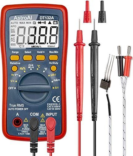
Digitalmultimeter mit Messleitungen
AstroAI DT132A AUTO MAX MIN APO DC AC °C kΩ% mV V Hz/Duty °F Ω Hz% µA mA A= OFF True RMS AUTO POWER OFF EN61010-1 CAT II 600V CAT III 300V A COM INPUT MAX 10A 10SEC EACH 15MIN MAX 500mA FUSED MAX 600V
in „DS18B20 Temperatursensor mit Multimeter messen“ · Mikrocontroller und Digitale Elektronik · · Fotos
-
PDF
MA2B150__001.pdf
°Rating Unit e . Reverse voltaMA2B150 VR 35 V 24 min.4±0.5φ 1±0.1e0. MA2B162 75 c Cathoded snodeφ reverse voltaMA2B162 VRRM 75 n V cle Forward current (AverageIF(AV) 10a mA e iecy Non-repetitive peak forwIFSMent 500 mA u uctl Junction
in „Datenblatt Diode Typ MA150?“ · Analoge Elektronik und Schaltungstechnik ·
-
 Bild
Diagramme einer Durchlaßkurve und Gruppenlaufzeit
Y 6901 ZF 479,50 MHz Durchlaßkurve -10 dB 0 10 20 30 40 50 60 70 440 450 460 470 480 490 500 510 520 MHz Weitabselektion -10 dB 0 10 20 30 40 50 60 70 440 460 480 500 520 540 560 580 600 620 660 MHz Durchlaßkurve und Gruppenlaufzeit (GD) Y 6901 50 ms 40 30 20 10 0 -10 -20 -30 -40 -50 -2 dB -1 0 1 2 3 4 5 6 460 464 468 472 476 480 484 488 492 496 500 MHz Siemens Aktiengesellschaft 396 397
in „Datenblatt für OFWY6950“ · HF, Funk und Felder · · Diagramme

-
PDF
b82450a_e-1.pdf
Inductors Transponder coils Size 7.8 u 2.7 u 2.7 (mm) Series/Type: B82450A*E Date: August 2019 a~í~=pÜÉÉí ¤▯TDK Electronics AG 2019. Reproduction, publication and dissemination of this publication, enclosures hereto and the information contained therein without TDK Electronics
in „Schlüsselcodes in EEPROM identifizieren“ · Fahrzeugelektronik ·
-
PDF
VHF-COMM.1984.2--b.pdf
28 kHz for FSK/ ATTY XF·919 Peak separation 2 kHz CW-Fitters _ still in crscrete technology: Type 6dB Bandwidth Crystals Shape-Factor Termination case Xf-9M 500 H, 4 6OdB :6dB4.4 sooc! 30 pF 2 XF-9NB 500 H, 8 6OdB :6 <JE322 500 (11130pF 1 Xf-9P ' 250 Hz 8 5OdB :6dB2.2 500 !} , 3pF 1 • New I K RIST AL LV ER A RB EITU N G N EC K AR B ISCH O FSH E IMG M B H 0-6924 Nee:karbischolsheim - Postfach 61 ' Tel. 01263 /6301
-
PDF
0900766b8147ba33.pdf
verfügbar • Optional mit Ausgang als Stillstandüberwachung Bestellschlüssel 6.522 . 01 X . 3 X 0 a b a Ausgang b Schaltpegel der Eingänge Lieferumfang 1 = Optokoppler-Ausgang 0 = Standard (HTL) – Digitalanzeige 2 = kein Ausgang A = 4 ... 30 V DC – Spannbügel – Frontrahmen f. Schraubbefestigung (T008181
in „[V] Diverses“ · Markt ·
-
PDF
Schaltplan_Anschaltung_an_DT-830B.pdf
BAT1 1 BATTERY9V 1 2 2 3 3 4 R15 4 5 5 6 1M A 6 R17 geht fast immer beim Anloeten kaputt A 7 7 8 8 B B C C D D TITLE: Anschluss am DT-830B REV: 1.0 Company: Sheet: 1/1 Date: 2023-05-14 Drawn By: 1 2 3 4 5
in „Suche günstiges Multimeter mit Schaltplan“ · Analoge Elektronik und Schaltungstechnik ·
-
PDF
-
PDF
epcos-B59-inrush-coated.pdf
ref C th τth Approvals Ordering code (typ.) V AC V DC % °C J/K s C1412 440 620 120 ±25 130 2.1 100 ▯ B59412C1130B070 C1451 440 620 56 ±25 130 2.1 100 ▯ B59451C1130B070 C750 260 360 25 ±25 115 1.0 100 X B59750C0120A070 C751 260 360 50 ±25 115 1.4 120 X B59751C0120A070 C755 560 800 500 ±25 110 1.4 120 X
in „Einschaltstrombegrenzer, R oder NTC, Ausfallszenario“ · Analoge Elektronik und Schaltungstechnik ·
-
PDF
U2100B_Data_sheet.pdf
Type Number Package Remarks U2100B-xY DIP8 Tube U2100B-xFPY SO8 Tube U2100B-xFPG3Y SO8 Taped and reeled 9. Package Information Package DIP8 Dimensions in mm 9.8 7.77 9.5 7.47 1.64 1.44 4.8 max 6.4 max 3.3 0.5 min 0.36 max 0.58 9.8 0.48
in „Fehlersuche Steinel Bewegungsmelder“ · Analoge Elektronik und Schaltungstechnik ·
-
PDF
panasonic_ncr18650b-2.pdf
4000 Discharge Capacity / mAh 2G23X0KYKU Discharge Temperatum pera re Charaharacteristics for NCR18650B650B 1S cell-1 Charge:CC-CV:1.625A-4.20V(65.0mA cut) 1.-202.-103.04.25 5.406.457.60 Discharge:CC:3.25A(E.V.:2.50V) 4.5 4.0 V / e3.5 a l V l3.0 40 e 25 C 0 2.5 -10 -20 2.0 0 500 1000 1500 2000 2500 3000 3500 4000 Discharge Capacity / mAh 2G23X0KYKU arge C haracteristics for C R18650B 1S Ch racteristics for NCR18650B No.1 Charge:CC-CV:1.625A-4.20V(65.0mA cut) 4.5 5000 Cell Voltage V4.0 4000 4000 / A h m A g3.5 3000 / 3000 / l Capacity t o e i V3.0 45 2000 r 2000 a e 25 C a C 0 C 2.5
in „Welche Zellchemie hat die Panasonic NCR18650B?“ · Analoge Elektronik und Schaltungstechnik ·
-
PDF
ST8918L6708-B.pdf
ST8918L6708-B.pdf
in „Schrittmotor von Nanotec“ · Mikrocontroller und Digitale Elektronik ·
-
PDF
L293_B_E_ST.pdf
L293E has external connection ofoard. PIN CONNECTION (Top view) POWERDIP (16+2+2) - L293E DIP16 - L293B July 2003 1/12 L293E L293B BLOCK DIAGRAMS DIP16 - L293B POWERDIP (16+2+2) - L293E 2/12 L293E L293B SCHEMATIC DIAGRAM (*) In the L293 these points are not externally available. They are internally connected
in „L293D Motortreiber, Highsidetreiber Technologie.“ · Mikrocontroller und Digitale Elektronik ·
-
PDF
0900766b80030f65.pdf
battery fully charged, although a high printing duty cycle may reduce the charge in the battery. N.B. Operation from the charger alone is not possible: a battery pack must always be fitted. Battery packs are normally supplied discharged for safety reasons. When the Ap863 is used with the direct mains powered PSU (option B), or the direct vehicle adaptor (option C), an external charger is not required. However, making a connection to the ‘Charger’ input will not damage the printer, and may be used to force the Ap863 to
-
PDF
NFDWJ130B-V1.pdf
Ratio vs Duty Allowable Forward Current TA=25°C 10000 A m t 2700 e r 1800 流 C 電 d 順 a 1000 容 w 許 o F b a o l A 100 1 10 100 デューティー比 Duty Ratio(%) 9 NICHIA STS-DA1-3929D <Cat.No.160404> OPTICAL CHARACTERISTICS NFDWJ130B-V1 * 本特性は参考です。 管理番号 No. STS-DA7-8305 All characteristics shown are for reference only
in „POWER LED Treiber 45W COB“ · Mikrocontroller und Digitale Elektronik ·
-
PDF
DYPTH01B-SPI_Datasheet.pdf
http://www.dypsensor.com TEL:0755-33867781 FAX:0755-33867780 DYPTH01B-SPI Temperature & Humidity Sensor - Relative humidity and temperature sensor - Pre-calculated temperature and humidity read out, no extra calculation needed - Dew Point Calculation possible - Fully Calibrated
in „Luftfeuchtigkeitssensor an Arduino UNO“ · Mikrocontroller und Digitale Elektronik ·
-
PDF
Envilight_DRV450B022017.pdf
Maximalstrom wird für alle vier Kanäle gemeinsam eingestellt. Technische Daten Features WiFi IEEE802.11b/g/n (optional) NRF24L01 GFSK (optional) Eingangsspannung Max. 48V DC LED-Spannung Bis zu 42V DC LED-Strom Max. 2A pro Kanal Anzahl Kanäle 4 Helligkeitssteuerung Pro Kanal: 800 Stufen Strombereich 0..2A