-
PDF
15C02CH-_CD_-.pdf
400 MHz Output Capacitance Cob VCB =10V, f=1MHz 4 pF Collector-to-Emitter Saturation VoltaVCE (sat) IC=400mA, B =20mA 140 280 mV Base-to-Emitter Saturation Voltage VBE (sat) IC=400mA, B =20mA 0.9 1.2 V
in „SMD-Bauteil cd 2 D4“ · Analoge Elektronik und Schaltungstechnik ·
-
Datei
usb.c
define EpCtrlMaxLen 64 #define EpCtrlLenId ((1<<15)|(1<<10)) #define EpBulkMaxLen 64 #define EpBulkLenId ((1<<15)|(1<<10)) #define EpIntMaxLen 8 #define EpIntLenId (4<<10) /******* Pufferlängen und Längen-Codes ****
in „STM32 USB Übertragungsproblem mit Code von S.F.“ · Mikrocontroller und Digitale Elektronik ·
-
PDF
Si4734-35-C40.pdf
1,2,3 (VDD= 2.7 to 5.5 VIO= 1.85 to 3.6AV, T = –20 to 85 °C) Parameter Symbol Test Condition Min Typ Max Unit SCLK Frequency fSCL 0 — 400 kHz SCLK Low Time LOW 1.3 — — µs SCLK High Time tHIGH 0.6 — — µs SCLK Input to SDIO Setup SU:STA 0.6 — — µs (START) SCLK Input to SDIO Hold HD:STA 0.6 — — µs (START
in „[V] LCD Display, xMega128 mit USB, AM/FM Radio Empfänger“ · Markt ·
-
PDF
epcos-T14K.pdf
VDC Operating DC voltage VV Varistor voltage max Maximum surge current C typ Typical capacitance W max Maximum energy absorption 2 For further information please contact your EPCOS sales office. © EPCOS AG 2014 ThermoFuse Varistors, T Series Maximum
in „Varistor mit Anzapfung?“ · Analoge Elektronik und Schaltungstechnik ·
-
PDF
Metrawatt-MA_5D.pdf
~O 30~O V- A digil'digit 8 Einflul3grol3e Einflul3bereich Dampfung Mel3groBe Gleichtakt- St6rgroBe max, 1000 V - ~120 dB Gleich- und st6rspannung St6rgr6Be max, 1000 V- f120 dB Wechselspannung 50 Hz, 60 Hz, sinus Serienst6rspannung StorgroBe V- 2facher MeBbereich- f; 60 dB Gleichspannung endwert, max
in „S: DMM mit dB-Anzeige“ · Markt ·
-
PDF
Metrawatt-MA_5D.pdf
~O 30~O V- A digil'digit 8 Einflul3grol3e Einflul3bereich Dampfung Mel3groBe Gleichtakt- St6rgroBe max, 1000 V - ~120 dB Gleich- und st6rspannung St6rgr6Be max, 1000 V- f120 dB Wechselspannung 50 Hz, 60 Hz, sinus Serienst6rspannung StorgroBe V- 2facher MeBbereich- f; 60 dB Gleichspannung endwert, max
in „Metrawatt MA5D Abgleichanleitung A DC Bereich“ · Analoge Elektronik und Schaltungstechnik ·
-
PDF
BT139-800G.pdf
Tj= 25 °C unless otherwise stated. Symbol Parameter Conditions BT139 BT139-F BT139-G Unit Min Typ Max Min Typ Max Min Typ Max V GT gate trigger VD= 12 V; - 0.7 1.5 - 0.7 1.5 - 0.7 1.5 V voltage T = 0.1 A; Figure 7 VD = 400 V; 0.25 0.4 - 0.25 0.4 - 0.25 0.4 - V T = 0.1 A; T = 125 °C j ID off-state VD
in „Triac direkt mit ATTiny steuern?“ · Mikrocontroller und Digitale Elektronik ·
-
PDF
150120GS75000.pdf
direction Start Carrier Tape Cover Tape F A No Component Components No Component min.160mm min.100mm min. 400mm R A B C D N W1 W2 W3 W3 packaging is reffered to the international standard IEC 60286-3:2013 Tape width 8 mm 178,0 1.5. 12.8 20.2 50n. 8.45 14.4 7.9. 10.9 tolerance typ. typ. +0,3/ -0,1 ref. max.
in „LED leuchten nicht mit Vorwiderstand“ · Analoge Elektronik und Schaltungstechnik ·
-
PDF
B82790_Epcos.PDF
B82790-S0***-N2 Dimensional drawing 1,9±0,2 1 0 5 2 0 0 , 0 . 5 x a , , m m ± ± 6 , , , , 0. 5 4 0 0 6,0max. A max.0,1 A Markingftung 7,1max. 9_0,4 0,2 SSB1015-Y Layout recommendation 253 04/00 Chokes for Data and Signal Lines B82790-C0***-N2 Double Chokes B82790-S0***-N2 General technical data Rated voltage
in „Stromversorgung für Hausbussystem“ · Analoge Elektronik und Schaltungstechnik ·
-
Datei
SMRM_V4_Teil1_template__2_.c
eingebunden werden (bitte Punkte passend ersetzen) #include ... #include ... #include ... #include ... // MAX30102 I2C device ID & Konfigurationsregister Adressen #define MAX30102_ID 0xAE #define MAX30102_REG_INT_STATUS 0x00 #define MAX30102_REG_INT_EN 0x02 #define MAX30102_REG_FIFO_DATA 0x07 #define MAX30102
in „PPG-Sensor (MAX301 102) über I2C-Schnittstelle (Hilfe)“ · Mikrocontroller und Digitale Elektronik ·
-
Bild
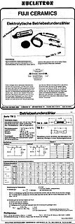
Datenblatt Fuji Ceramics elektrolytische Betriebsstundenzähler
°C Schock: 50 G, 1 ms, 1,5 mm Feuchtigkeit: bei 40 °C, 95 % h Betriebsstundendauer: 60.000 Stunden Max. Rekristallisation: 200 µm Glashaltrom Betriebsstunden 10 V 50 100 200 1000 2000 5000 10000 12 V 30 50 100 200 400 1000 2000 5000 10000 24 V 10 30 50 100 200 400 1000 2000 5000 10000 AC 200 300 400
in „Unbekannte Anzeige-Intrumente“ · Analoge Elektronik und Schaltungstechnik · · Screenshots
-
PDF
P600A-S.pdf
Spitzensperrspannung Stoßspitzensperrspannung VRRM[V] V RSM[V] P600A 50 50 P600B 100 100 P600D 200 200 P600G 400 400 P600J 600 600 P600K 800 800 P600M 1000 1000 P600S 1200 1200 1 Max. average forward rectified current, R-load TA= 50°C FAV 6 A ) Dauergrenzstrom in Einwegschaltung mit R-Last 1 Repetitive peak forward
in „Dioden mit großem trr (Sperrerholzeit, reverse recovery time)“ · Analoge Elektronik und Schaltungstechnik ·
-
PDF
LM2937.pdf
mA ≤ I ≤ I 4.85 7.76 9.70 V(Min) OUT OUTmax 5.00 4.75 8.00 7.60 10.00 9.50 V(Min) 5.15 8.24 10.30 V(Max) 5.25 8.40 10.50 V(Max) Line Regulation (VOUT + 2V) ≤ VIN≤ 26V, 15 50 24 80 30 100 mV(Max) I = 5 mA OUT Load Regulation 5 mA ≤ IOUT ≤ OUTmax 5 50 8 80 10 100 mV(Max) Quiescent Current (VOUT + 2V) ≤
in „Minimale Hardware zum Auto CAN-Bus abhören“ · Mikrocontroller und Digitale Elektronik ·
-
PDF
vl53l0x_VL53L0X.pdf
output capacitance (SDA) - - 10 pF Cin Input capacitance (SCL) - - 4 pF C L Load capacitance - 125 400 pF 1. The maximum bus s2eed is also limited by the combination of 400pF load capacitance and pull-up resistor. Please refer to the I C specification for further information. 20/40 DocID029104 Rev 3
in „Distanzmessung mit dem Pi auf 1mm genau“ · Mikrocontroller und Digitale Elektronik ·
-
PDF
fil_mur_filter-fm-alt-p61e5.pdf
MJA10-A SpuriousAttenuation Part Number 3dBBandWidth 20dBBandWidth InsertionLoss (9 12MHz) (kHz) (kHz) max. (dB) (dB) min. SFE10.7MA5A10-Z 280T50 590(480) 2.5T2.0 30(42) !DIMENSIONS SFE10.7MS2A10-Z 230T50 520(400) 3.0T2.0 35(43) SFE10.7MS3A10-Z 180T40 470(360) 3.5T1.5 35(43) 7.0T2.0 SFE10.7MJA10-Z 150T30
in „Kann man einen Parallelschwingkreis mit einem nanoVNA ausmessen und die Ergebnisse nachvollziehen?“ · HF, Funk und Felder ·
-
Datei
WCU_Kilobot_Schematic.txt
-5000 -950 OPEN 2 10 255 -5000 1290 -5000 -1200 OPEN 2 10 255 0 800 -5000 800 OPEN 2 10 255 -5000 -400 -7500 -400 CLOSED 7 10 255 0 -1200 0 1290 -5000 1290 -5000 400 -7500 400 -7500 -1200 0 -1200 OPEN 2 10 255 -5010 0 -7500 0 OPEN 2 10 255 -5000 -800 -7500 -800 OPEN 2 10 255 -6000 400 -6000 -1200 OPEN
-
PDF
SF_Sensofoil_Produktinfo_DE_02_2012_1_.pdf
Widerstandsmischungen, bevorzugt 35 /Square Baugrößen bis 800mm Länge als lineare Ausführung, bis 400mm Durchmesser als radiale Ausführung ® SENSOFOIL FR4 - Widerstandsbahn auf FR4 gedruckt: Linearität: 2 %, optional 0,5 % für lineare Sensofoil ® 4 %, optional 1,5 % für radiale Sensofoil Widerstand
in „ADW - HB628 von H-Tronic - Folienpotentiometer“ · Mikrocontroller und Digitale Elektronik ·
-
PDF
rgpr30bm40-e.pdf
RGPR30BM40 400V 30A Ignition IGBT Datasheet lOutline BV 40030V TO-252 CES I 30A (2) C V 1.6V (1) CE(sat) (Typ.) (3) E 300mJ AS lFeatures lInner Circuit 1) Low Collector - Emitter Saturation Voltage (2) 2) High Self-Clamped
in „Transistorzündung für Moped mit LL-Mosfet/ -IGBT (Einstiegsprojekt)“ · Fahrzeugelektronik ·
-
PDF
155110_AL-60P06.pdf
Min. Sound Output at 10cm dB 85 Rated Voltage V 6 Operating Voltage V 3~8 Resonant Frequency Hz 2.400 Max. Current Consumption mA 40 Coil Resistance 455 Coil Impedance 80 Operating Temperature °C -25~+70 Storage Temperature °C -30~+80 Weight g 2 Value applying at (rated voltage, 2.400Hz, ½ duty square wave) Value applying at (2.400Hz, sine wave, measuring current 60 A) DIMENSIONS : (Unit: mm) Frequency response: Adresse: Felix-Wankel-Str. 35 73760 Ostfildern/Nellingen Tel: +49-711/3414023 Fax: +49-711/3414024 E-mail: info@ekulit.de
in „Problemchen DCF-Wecker“ · Mikrocontroller und Digitale Elektronik ·
-
Datei
sms.c
FDEV_SETUP_WRITE ); SMS_DECODE_DATA_T sms_dec_data; SMS_TELNR_LIST_T sms_telnr_list[SMS_TELNR_LIST_MAX]; char sms_last_caller[SMS_TELNR_MAX_LEN+1]={""}; uint8_t anz_klingeln=0; /** * konkrete Zuordnung von Befehlsstrings zu einer Funktion vom Typ "uint8_t <fname> (uint8_t dat)" */ const SMS_CMD_LIST_T
in „UART von Mega32 auf Mega168 anpassen“ · Mikrocontroller und Digitale Elektronik ·
-
PDF
TI74HC244.pdf
TEST CONDITIONS VCC UNIT MIN TYP MAX MIN MAX MIN MAX 2 V 1.9 1.998 1.9 1.9 OH = –20 A 4.5 V 4.4 4.499 4.4 4.4 V V = V or V V OH I IH IL 6 V 5.9 5.999 5.9 5.9 OH = –6 mA 4.5 V 3.98 4.3 3.7 3.84 OH = –7.8 mA 6 V 5.48 5.8 5.2 5.34 2 V 0.002
in „SN74HCT244?“ · Mikrocontroller und Digitale Elektronik ·
-
Bild
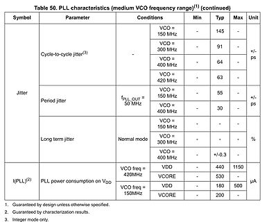
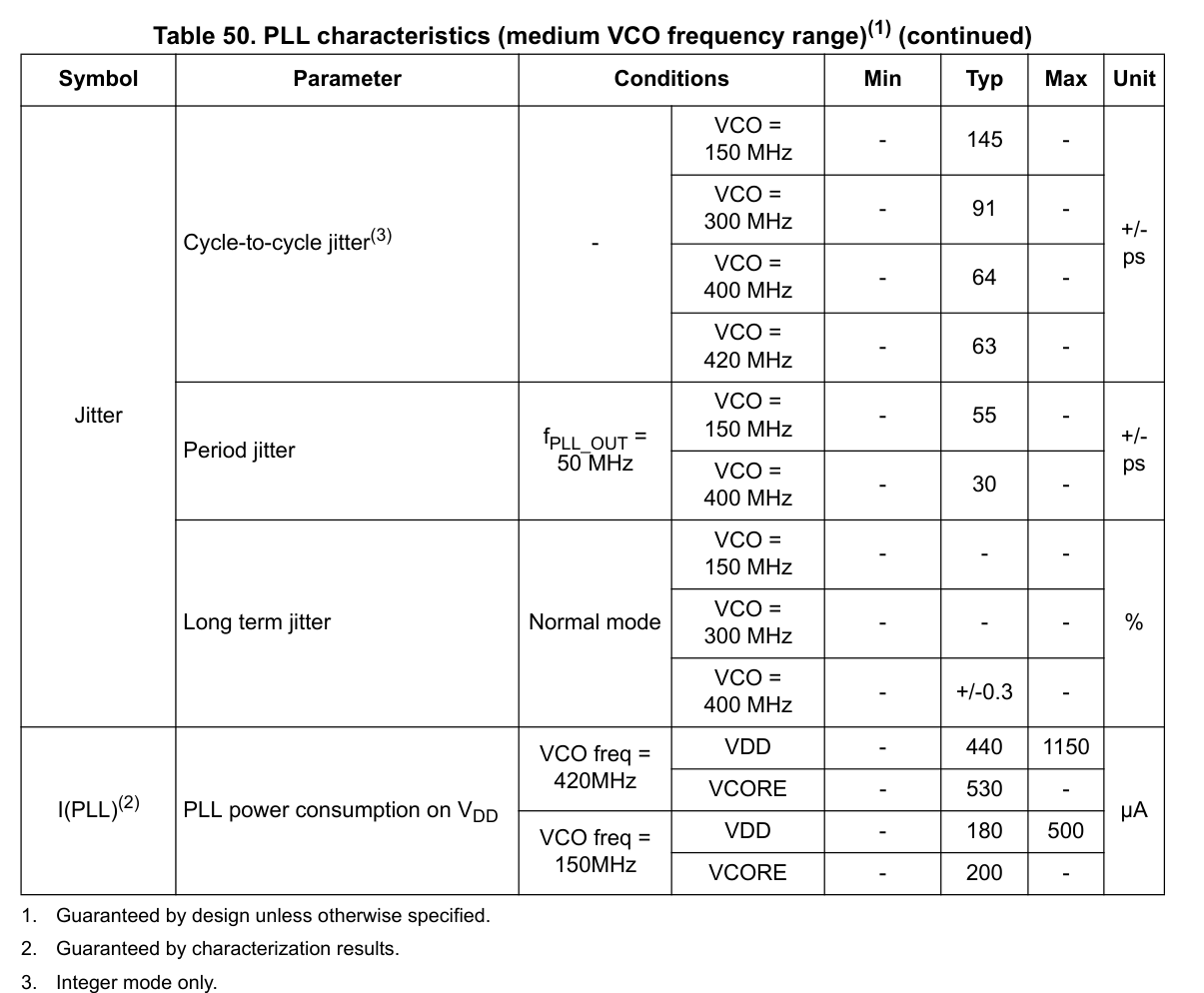
Tabelle der PLL-Charakteristika
PLL characteristics (medium VCO frequency range)(1) (continued) Symbol Parameter Conditions Min Typ Max Unit Jitter Cycle-to-cycle jitter(3) VCO = 150 MHz - 145 - +/- ps VCO = 300 MHz - 91 - VCO = 400 MHz - 64 - VCO = 420 MHz - 63 - Period jitter fPLL_OUT = 50 MHz VCO = 150 MHz - 55 - +/- ps VCO = 400 MHz - 30 - Long term jitter Normal mode VCO = 150 MHz - - - % VCO = 300 MHz - - - % VCO = 400 MHz - +/-0.3 - % I(PLL)(2) PLL power consumption on VDD VCO freq = 420MHz VDD - 440 1150 VCORE - 530 µA
in „STM32H743 PLL“ · Mikrocontroller und Digitale Elektronik · · Screenshots
-
Bild
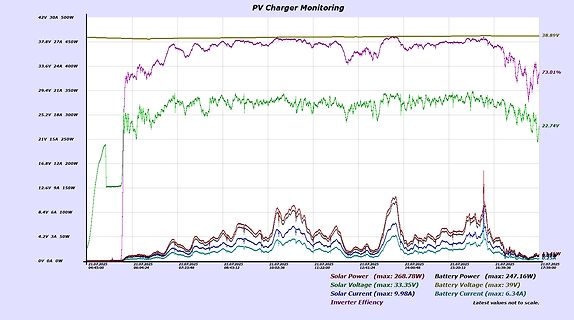
Diagramm der PV-Laderegister-Überwachung
PV Charger Monitoring 42V 30A 500W 37.8V 27A 450W 33.6V 24A 400W 29.4V 21A 350W 25.2V 18A 300W 21V 15A 250W 16.8V 12A 200W 12.6V 9A 150W 8.4V 6A 100W 4.2V 3A 50W 0V 0A 0W Solar Power (max: 268.78W) Solar Voltage (max: 33.35V) Solar Current (max: 9.98A) Inverter Effiency Battery Power (max: 247.16W) Battery Voltage (max: 39V) Battery Current (max: 6.34A) 38.89V 73.01% 22.74V
in „MPP Tracker Optimierung“ · Analoge Elektronik und Schaltungstechnik · · Screenshots
-
PDF
SFH_7060__Lead__Pb__Free_Product_-_RoHS_Compliant.pdf
(F = 20 mA, t p 20 ms) Centroid Wavelength (typ. 940 (±10) nm centroid (F = 20 mA, t p 20 ms) (max.)) Spectral bandwidth at 50% of I max (typ.) 42 nm (F = 20 mA, t p 20 ms) Half angle (typ.) ± 60 ° Rise and fall time of e (typ.) tr f 16 ns (10% and 90% of I ) e max (F = 100 mA, t p 16 µs,
in „Wie funktioniert der O2-Sensor von einem Pulsoximeter?“ · Analoge Elektronik und Schaltungstechnik ·
-
PDF
SFH_7060__Lead__Pb__Free_Product_-_RoHS_Compliant.pdf
(F = 20 mA, t p 20 ms) Centroid Wavelength (typ. 940 (±10) nm centroid (F = 20 mA, t p 20 ms) (max.)) Spectral bandwidth at 50% of I max (typ.) 42 nm (F = 20 mA, t p 20 ms) Half angle (typ.) ± 60 ° Rise and fall time of e (typ.) tr f 16 ns (10% and 90% of I ) e max (F = 100 mA, t p 16 µs,
in „Transimpedanzwandler für SFH7060“ · Analoge Elektronik und Schaltungstechnik ·
-
PDF
UAGstepper-Motor.pdf
0.40 0.4 0.20 0.3 0.30 0.3 0.15 0.2 0.10 0.2 0.20 0.1 0.10 0.1 0.05 0 0.00 0.0 0.00 0 100 200 300 400 500 600 0 100 200 300 400 500 600 700 800 fS/ Hz fS/ Hz UAG2 - Pull-in range UAG2 - Pull-out range 0.5 0.25 0.6 0.60 M/ cNm P/ W M/ cNm P/ W 0.5 0.50 0.4 0.20 0.4 0.40 0.3 0.15 0.3 0.30 0.2 0.10 0.2 0.20 0.1 0.05 0.1 0.10 0.0 0.00 0.0 0.00 0 50 100 150 200 250 300 350 400 450 500 0 100 200 300 400 500 600 700 800 fS/ Hz fS/ Hz M - ED 100 % P - ED 100 % M - ED 30 % P - ED 30 % Motor Products www.saia-burgess.com 34 | 35
in „Kleiner mobiler (Thermo-)Drucker für einfache Ansteuerung“ · Mikrocontroller und Digitale Elektronik ·
-
PDF
uag212.pdf
0.40 0.4 0.20 0.3 0.30 0.3 0.15 0.2 0.20 0.2 0.10 0.1 0.05 0.1 0.10 0 0.00 0.0 0.00 0 100 200 300 400 500 600 0 100 200 300 400 500 600 700 800 fS/ Hz fS/ Hz 0.5 UAG2 - Pull-in range 0.25 0.6 UAG2 - Pull-out range 0.60 M/ cNm P/ W M/ cNm P/ W 0.5 0.50 0.4 0.20 0.4 0.40 0.3 0.15 0.3 0.30 0.2 0.10 0.2 0.20 0.1 0.05 0.1 0.10 0.0 0.00 0.0 0.00 0 50 100 150 200 250 300 350 400 450 500 0 100 200 300 400 500 600 700 800 fS/ Hz fS/ Hz M - ED 100 % P - ED 100 % M - ED 30 % P - ED 30 % Actuators Catalogue www.saia-burgess.com 36 | 37
-
Bild
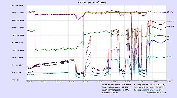
Diagramm der PV-Ladegerät-Überwachung
PV Charger Monitoring 42V 30A 500W 37.8V 27A 450W 33.6V 24A 400W 29.4V 21A 350W 25.2V 18A 300W 21V 15A 250W 16.8V 12A 200W 12.6V 9A 150W 8.4V 6A 100W 4.2V 3A 50W 0V 0A 0W Solar Power (max: 406.25W) Solar Voltage (max: 32.91V) Solar Current (max: 16.33A) Battery Power (max: 370.21W) Battery Voltage (max: 38.42V) Battery Current (max: 9.66A) Inverter Efficiency Latest values not to scale. 393.78W 358.09W 24.3V 16.2A 9.32A
in „MPP Tracker Optimierung“ · Analoge Elektronik und Schaltungstechnik · · Screenshots
-
Bild
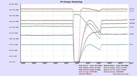
Diagramm der PV-Ladegerät-Überwachung
PV Charger Monitoring 42V 30A 500W 37.8V 27A 450W 33.6V 24A 400W 29.4V 21A 350W 25.2V 18A 300W 21V 15A 250W 16.8V 12A 200W 12.6V 9A 150W 8.4V 6A 100W 4.2V 3A 50W 0V 0A 0W Solar Power (max: 364.54W) Solar Voltage (max: 34.54V) Solar Current (max: 15.64A) Solar Energy: 0.007kWh Battery Power (max: 334.18W) Battery Voltage (max: 36.97V) Battery Current (max: 9.04A) Battery Energy: 0.007kWh Inverter Efficiency: 91.67%
in „Optimierung StepUp-Wandler“ · Analoge Elektronik und Schaltungstechnik · · Screenshots
-
Bild
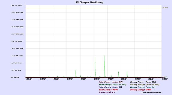
Diagramm der PV Charger Überwachung
PV Charger Monitoring 42V 30A 500W 40.47V 37.8V 27A 450W 33.6V 24A 400W 29.4V 21A 350W 25.2V 18A 300W 21V 15A 250W 16.8V 12A 200W 12.6V 9A 150W 8.4V 6A 100W 4.2V 3A 50W 0V 0A 0W Solar Power (max: 0W) Battery Power (max: 0W) Solar Voltage (max: 15.47V) Battery Voltage (max: 40.48V) Solar Current (max: 0A) Battery Current (max: 0A) Solar Energy: 0kWh Battery Energy: 0kWh Inverter Efficiency Latest values not to scale.
in „Lustige Funde beim Solaranlagen-Selbstbau“ · Offtopic · · Screenshots
-
PDF
TIC216_.pdf
REVISED MARCH 1997 0 Sensitive Gate Triacs 0 6ARMS TO-229 PACKAGE (TOP VIEW) 0 Glass Passlvated Wafer l 400 Vto800 VOff-Staate Voltage 0 Max lorof 5 mA(Quadrants 1- 3) Pin 2 1sIn electrtcal contaci with the mountfng base. MOCZACA absolute maximum ratingsover operating case temperature (unless otherwise noted
in „DMX Dimmerpack bauen“ · Mikrocontroller und Digitale Elektronik ·
-
PDF
BMP-5075R_.pdf
Electrical Specifications Outline Drawing FREQ. ATTENUATION VSWR POWER (MHz) (dB) (:1) (W) Flatness Max. Max. DC-100 100-1000 1000-2000 DC-100 100-1000 1000-2000 L--U Nom. MHz MHz MHz MHz MHz MHz DC-2000 5.7±0.1 0.2 0.3 0.4 1.06 1.22 1.4 0.25 Outline Dimensions ( inch) mm Typical Performance Data B D
-
Datei
life.c
include "driver.h" #include "xprintf.h" #include "command.h" #include "tools.h" // Game of Life #define MAX_X 79 #define MAX_Y 23 #define START_RANDOM 699 #define START_ZELLEN 400 // Anzahl der zum Start bevölkerten Felder #define GENERATIONS 5000 #define DEAD_CELL 0 #define ALIVE_CELL 1 // Zustände der nächsten
in „Retro Fieber: Z80 oder 68000 ?“ · Mikrocontroller und Digitale Elektronik ·
-
PDF
PCF8575.pdf
0 V; T = −40 to +85 °C; unless otherwise specified. DD SS amb SYMBOL PARAMETER CONDITIONS MIN. TYP. MAX. UNIT Supplies V supply voltage 2.5 − 5.5 V DD DD supply current operating mode; no load;− 100 200 A V = V or V ; I DD SS fSCL= 400 kHz DD(stb) standby current standby mode; no load; − 2.5 10 A V I
in „Vieleeeele Eingänge, viele Ausgänge.“ · Mikrocontroller und Digitale Elektronik ·
-
PDF
PCF8575.pdf
0 V; T = −40 to +85 °C; unless otherwise specified. DD SS amb SYMBOL PARAMETER CONDITIONS MIN. TYP. MAX. UNIT Supplies V supply voltage 2.5 − 5.5 V DD DD supply current operating mode; no load;− 100 200 A V = V or V ; I DD SS fSCL= 400 kHz DD(stb) standby current standby mode; no load; − 2.5 10 A V I
in „Lichtsteuerung über i2c - ULN2803A - S12-100“ · Mikrocontroller und Digitale Elektronik ·
-
Bild
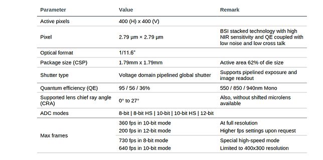
Tabelle mit Bildsensoreigenschaften
Parameter Value Remark Active pixels 400 (H) x 400 (V) Pixel 2.79 µm x 2.79 µm BSI stacked technology with high NIR sensitivity and QE coupled with low noise and low cross talk Optical format 1/11.6" Package size (CSP) 1.79mm x 1.79mm Active
in „Bauteile: PocketBeagle, smart aufgebaute LEDs, ESP32 mit STM32 uvam“ · Mikrocontroller und Digitale Elektronik · · Screenshots
-
PDF
ths6012.pdf
V Number of 150- Loads Figure 33. Figure 34. DIFFERENTIAL GAIN AND PHASE vs NUMBER OF 150-Ω LOADS 400-mV STEP RESPONSE 0.15 0.25 400 VCC = ±5 V RF= 1 k Gain = 2 300 0.12 f = 3.58 MHz 0.20 40 IRE Modulation ° V 200 100 IRE Ramp − m % s − − 0.09 0.15 a g 100 a P t G a o a n t 0 n r u r 0.06 0.10 e t e
in „DDS Endstufe DC-50 Mhz“ · Analoge Elektronik und Schaltungstechnik ·
-
PDF
Seagate-Constellation-2-Datasheet.pdf
Interface Access Speed (Gb/s) 6.0, 3.0, 1.5 6.0, 3.0, 1.5 6.0, 3.0, 1.5 6.0, 3.0, 1.5 6.0, 3.0, 1.5 Max. Sustained Transfer Rate (MB/s) 115 115 115 115 115 Seek Time, Average Read/Write (ms) 8.5/9.5 8.5/9.5 8.5/9.5 8.5/9.5 8.5/9.5 Average Latency (ms) 4.16 4.16 4.16 4.16 4.16 Interface Ports Dual Dual
in „Benutzen SATA Platten die 3,3V auch?“ · PC Hard- und Software ·
-
PDF
1640586162378_1895.pdf
Variables The next parameter which must be calculated is the maximum allowable temperature rise, T R(max) RθJC RθJA (COMPONENT VARIABLES) (APPLICATION VARIABLES) T R(max) T J(max) TA(max) (3) Leadframe Size and Material Mounting Pad Size, Material, and Location where No. of Conduction Pins Placement of
in „ESP32-C6 und LDO“ · Mikrocontroller und Digitale Elektronik ·
-
PDF
TaiyoYuden_UMK325BJ106KM.pdf
3.6±0.2 325 2.8±0.2 3.6±0.2 432 3.7±0.2 4.9±0.2 [Unit: mm] Dimensions Type C D E F G H J K t - 1.1max 107~ 8.0±0.3 3.5±0.05 4.0±0.1 Paper Paper 325 1.75±0.1 2.0±0.05 4.0±0.1 φ1.5 tape) tape) +0.1/-0 3.4max 0.6max 432 12.0±0.3 5.5±0.05 8.0±0.1 4.0max 0.6max [Unit: mm] E C B R D t A W Dimensions of Reel
in „Strombelastbarkeit Kondensator“ · Analoge Elektronik und Schaltungstechnik ·
-
PDF
Weidezaun_S04_ELV50.pdf
Bohrfutter 1-10mm AkkubohrmaschineMuster1 50Wdg@0,5R@1,685mH, 250Wdg@5,8R@44mH, 125Wdg@3R@11mH 0 / 12V@400mA 85-265Vac 120-370Vdc PCB 30x21x18mm, THX208 700/800V 4,8-9V 2,4mA 230mA SO8 TL431 U3 LM1117-3,3 PWM 4,7uF 400V 470uF 25V 4 AC_DC1 NT 12V@400mA 3,5W - 1 5 6 L-ACin OUT Stecker-NT 12V 1A 12W P LM1117
in „Weidezaun gegen Schnecken mit Netztrafo und Rohr DN160 für Hobbygärtner“ · Projekte & Code ·
-
PDF
A100-BC327_28_BC337_38.pdf
Current IEBO VEB =5V, C =0 <10 µA DC Current Gain hFE C =500mA,V CEV >40 I =100mA,V =1V C CE 100-600 100-400 100-600 Group-10 63-160 63-160 Group-16 100-250 100-250 Group-25 160-400 160-400 Group-40 250-600 250-600 Collector Emitter Saturation Voltage VCEsat)* IC=500mA,I B50mA <0.70 V Base Emitter On Voltage
in „Tansistor brechnen allgemein“ · Analoge Elektronik und Schaltungstechnik ·
-
PDF
stth20002tv.pdf
diodth(c)x R STATIC ELECTRICAL CHARACTERISTICS (per diode) Symbol Parameter Test conditions Min. Typ Max. Unit R * Reverse leakage current T j 25°C V R V RRM 100 µA Tj= 125°C 80 800 VF** Forward voltage drop Tj= 25°C IF= 100A 1.05 V IF= 200A 1.20 Tj= 150°C IF= 100A 0.75 0.85 IF= 200A 1.05 Pulse test: *
in „Warum mehrere Dioden parallel“ · Analoge Elektronik und Schaltungstechnik ·
-
PDF
TL061CP.pdf
± 15 V (unless otherwise noted) CC ± TL061M TL064M PARAMETER TEST CONDITIONS † TL062M UNIT MIN TYP MAX MIN TYP MAX V = 0, TA= 25°C 3 6 3 9 VIO Input offset voltage O mV R S 50 Ω TA= –55°C to 125°C 9 15 Temperature coefficientV = 0, R = 50 Ω, α VIO O= S 10 10 µV/°C of input offset voltageTA –55°C to 125
in „Messspannung von Shunt verstärken, kfz“ · Analoge Elektronik und Schaltungstechnik ·
-
PDF
pc715v0nszx_e.pdf
Collector- emitter Voltage Current 2 000 16 V =2V F =1mA Ta=25˚C 1 800 CE 0.9mA Ta=25˚C 14 ) 1 600 PC(MAX.) ( ) 12 0.8mA R 1 400 A C ( o 1 200 t 10 0.7mA a e 0.6mA r 1 000 r 8 s c a 800 t 0.5mA t e 6 e 600 o 0.4mA r C 4 C 400 0.3mA 2 200 0.1mA 0.2mA 0 0 0.1 1 10 0 1 2 3 4 5 6 7 8 9 10 11 12 13 Forward current
in „Optokoppler bei geringen Strömen“ · Analoge Elektronik und Schaltungstechnik ·
-
Datei
usb.c
0x40006000 #define EpCtrlMaxLen 64 #define EpCtrlLenId ((1<<15)|(1<<10)) #define EpBulkMaxLen 64 #define EpBulkLenId ((1<<15)|(1<<10)) #define EpIntMaxLen 8 #define EpIntLenId (4<<10) // EP0 = control #define Ep0TxOffset 0 // 64
in „STM32G484 USB CDC Code läuft nur wenn mit <= -O1 kompiliert“ · Mikrocontroller und Digitale Elektronik ·
-
PDF
MAX712-MAX713.pdf
to +70°C Dice* kits are available: Order the MAX712EVKIT-DIP for quick MAX712EPE -40°C to +85°C 16 Plastic DIP evaluation of the linear charger, and the MAX713EVKIT- SO to evaluate the switch-mode charger. MAX712ESE -40°C to +85°C 16 Narrow SO MAX712MJE
in „MAX1775_Verständnisproblem“ · Analoge Elektronik und Schaltungstechnik ·
-
PDF
MAX712-MAX713.pdf
to +70°C Dice* kits are available: Order the MAX712EVKIT-DIP for quick MAX712EPE -40°C to +85°C 16 Plastic DIP evaluation of the linear charger, and the MAX713EVKIT- SO to evaluate the switch-mode charger. MAX712ESE -40°C to +85°C 16 Narrow SO MAX712MJE
in „Kurz vorm Verzweifeln“ · Analoge Elektronik und Schaltungstechnik ·
-
PDF
DS_SJEP120R100_rev2.1.pdf
Operating Temperature D(2,4) - R of 0.100 Ω DS(on)max - Voltage Controlled 4 - Low Gate Charge - Low Intrinsic Capacitance G(1) Applications: - Solar Inverter TO-247 2 3 1 - SMPS S(3) - Power Factor Correction Internal Schematic - Induction Heating - UPS
in „Siliziumkarbid-JFETS“ · Analoge Elektronik und Schaltungstechnik ·
-
PDF
0900766b8144620c_1_.pdf
Current DCTest Current VCat 200A tance f = RMS DC (2ms) 8 x 20µs Current (8/20µs) 1MHz V V W I Min V Max V C M(AC) M(DC) TM TM N(DC) C (V) (V) (J) (A) (V) (V) (V) (V) (pF) BA Series V131BA60 130 175 450 50000 184.5 205 225.5 340 20000 V151BA60 150 200 530 50000 216 240 264 400 16000 V251BA60 250 330 880
in „Hochspannung überprüfen“ · Analoge Elektronik und Schaltungstechnik ·