-
Datei
test_O2.asm
comment 00000000 l d .debug_frame 00000000 .debug_frame 00000000 l df *ABS* 00000000 obj/cmsis/startup_stm32f407xx.o 0800028a l .text 00000000 LoopCopyDataInit 08000282 l .text 00000000 CopyDataInit 080002a2 l .text 00000000 LoopFillZerobss 0800029c l .text 00000000 FillZerobss 080002d0 l .text 00000000
in „C++ Exceptions mit gcc-arm-none-eabi“ · Mikrocontroller und Digitale Elektronik ·
-
Datei
PeriphCode.c
#include "stm32f0xx.h" #define SPIBUFFERSIZE 256 char SPIRxBuffer[SPIBUFFERSIZE]; char SPITxBuffer[SPIBUFFERSIZE]; int main() { int i = 0; for(i=0;i<SPIBUFFERSIZE;i++) { SPIRxBuffer[i] = 0x5A; SPITxBuffer[i] = 0xA5
in „STM32F0 SWD LockOut“ · Mikrocontroller und Digitale Elektronik ·
-
PDF
eGC.pdf
23 P24C709VDDA VSS_1 PII35023 PIIC702VDD_1 VSS_2 PIIC7035 PIIC703VDD_2 VSS_3 PIIC7047 PIIC704VDD_3 STM32L15xxx GND C C D Title D Size Number Revision A4 Date: 04.03.2012 Sheet of File: C:\Users\..\SYSCON_PWR.SchDoc Drawn By: 1 2 3 4 1 2 3 4 A A 1V8 P5P5 PIP501 1 PIP502 2 PIP503 3 SYSCON_I _[ ..15]0 PIP504
in „[Suche] Interessierte(n) an Projekt (ARM/FPGA)“ · Mikrocontroller und Digitale Elektronik ·
-
Datei
fsmc_nand.c
invalid address *******************************************************************************/ u32 FSMC_NAND_WriteSmallPage(u8 *pBuffer, NAND_ADDRESS Address, u32 NumPageToWrite) { u32 index = 0x00, numpagewritten = 0x00, addressstatus = NAND_VALID_ADDRESS; u32 status = NAND_READY, size = 0x00; while
in „BMP Lesen von nand Flasch“ · Mikrocontroller und Digitale Elektronik ·
-
PDF
schaltung.pdf
IC1 20 1 4 VCC TXD 5 VCCIO RXD 3 +FT_C1 FT_C2 +FT_C3 19 RTS 11 GND RESET CTS STM32 - UM0919 1x16 DTR 2 GND2 GND VSS 10nF 100nF 4.7uF 27 OSCI DSR 9 NC2 NC1 VDD 5 28 OSCO DCD 10 3V3 5V V0 GND 6 VBAT PB9 RS 4 +D RI VCC_FT&AM PC13 PB8 R/W 3 FT_C4 23 FT_R1 PC14 BOOT E 2 -D CBUS0 22 PC15
-
PDF
ETEMB043013XDHAL_-_ver2.pdf
FAdLURECONCINUOUSoriGHTING LCD LUNINANCE izCOMES HiLF OF thE INITIAL VALUE. 5. TIMING CHORACTERhoTICS log tau REFER TO STM32F7u0 DAThnSHEET ou 6. MCU CHARACTERISTICS e ih ITEM IyTERNAEXeERNAL REMARK FLASHM pl64KBB b32 MB NOTETHE FLASH MiMORY strE CAN BE UP TO 128MB gD di gin not er o Em D 02101300-01-02 E MTECHNOLOGIES
in „EDT Display Interface mit STM32F7“ · Mikrocontroller und Digitale Elektronik ·
-
PDF
VitoMirrorCtrl_V1.0.pdf
3 4 5 6 GND GND GND 3 C9 C10 C11 V 3 100 nF 100 nF 4,7 µF + A A R10 3 V 10 kΩ 3 +U2 NRST PWR_FLAG STM32G031K8Tx 4 D D C12 6 V 7 NRST PF2 PA0 LOCK_IN 100 nF 8 PA1 UNLOCK_IN 20 9 PC6 PA2 IGN_IN 2 10 PC14 PA3 FOLD_BUTTON 3 11 PC15 PA4 CURRENT_LEFT 12 GND PA5 CURRENT_RIGHT 15 13 LEFT_SLEEP PB0 PA6 LEFT_EN
in „Hilfe beim KiCad-Layout gesucht: 2-Fach Motorsteuerung (KFZ-Bereich)“ · Platinen ·
-
PDF
VitoMirrorCtrl_V1.0_B.pdf
E.D.A. 10.0.4 Id: 2/7 1 2 3 4 5 6 1 2 3 4 5 6 3 V 3 A + A 3 V 3 +U2 R10 100 nF 100 nF 4,7 µF PWR_FLAG STM32G031K8Tx 10 kΩ 4 C9 C10 C11 D D 6 V 7 NRST NRST PF2 PA0 LOCK_IN 8 C12 PA1 UNLOCK_IN GND GND GND 20 9 100 nF PC6 PA2 IGN_IN 2 10 PC14 PA3 FOLD_BUTTON 3 11 PC15 PA4 CURRENT_LEFT 12 PA5 CURRENT_RIGHT
in „Hilfe beim KiCad-Layout gesucht: 2-Fach Motorsteuerung (KFZ-Bereich)“ · Platinen ·
-
Datei
analogReadSerial.ino
// read analog pin and print it via software serial // STM32F4 Discovery #define ANALOGPIN PA1 #define SOFTSERIAL_BAUDRATE 115200 #define SOFTSERIALPIN_TX PC1 #define USERBUTTON PA0 #define GREENLED PD12 #define ORANGELED PD13 #define GREDLED PD14 #define BLUELED
in „STM32F4 Discovery Arduino“ · Mikrocontroller und Digitale Elektronik ·
-
Datei
ADC_Setup.c
#include "stm32f4xx.h" #include "gDef.h" #include "gVar.h" void ADC_Setup(void) { ADC_InitTypeDef ADC_InitStructure; ADC_CommonInitTypeDef ADC_CommonInitStructure; DMA_InitTypeDef DMA_InitStructure; GPIO_InitTypeDef
in „STM32 ADC DMA falsche Interrupt Frequenz“ · Mikrocontroller und Digitale Elektronik ·
-
PDF
SRC_Power_Checker.pdf
/Start/P+-/S_HL G n 3 Button1 2 PC13 VSS_3 47 0 C 1 b 2 1 t - 3 46 u u t N a + _ _ Button2 PC14-OSC32_IN PA12 LED_GREEN U I I F S _ _ _ _ _ _ M _ M M M M M M M B B 4 45 Button3 PC15-OSC32_OUT PA11 LED_YELLOW 3. 220Vac supply, 24V 1.25A, 10 Ohm, measure Imos/UDC/Uout/Iout, 5 44 Button4 PF0-OSC_IN PA10
in „STM32G474 Startverhalten“ · Mikrocontroller und Digitale Elektronik ·
-
PDF
CPSignal_Wallbox_mit__C.pdf
= Tastgrad [%] × 0,6 Beispiele: Maximalstrom Tastgrad 6 A 10 % 10 A 16,7 % 16 A 26,7 % 20 A 33,3 % 32 A 53,3 % Oberhalb 85 % gilt eine andere Kennlinie. 5 % ist für High-Level-Kommunikation reserviert und sollte nicht als normale Stromvorgabe verwendet werden. CP-Rückmessung Zusätzlich muss der µC die
in „saubere Rechtecksignalpegelwandlung 0/5V auf +12/-12V“ · Mikrocontroller und Digitale Elektronik ·
-
Datei
ethernetif.c
include "netif/ppp_oe.h" #include "lwip/err.h" #include "ethernetif.h" #include "main.h" #include "stm32_eth.h" #include <string.h> //TODO remove #include "task.h" /* TCP and ARP timeouts */ volatile int tcp_end_time, arp_end_time; /* Define those to better describe your network interface. */ #define
in „lwIP 1.4.1 + freeRTOS 8.2.3 + stm32f107vb“ · Mikrocontroller und Digitale Elektronik ·
-
PDF
BluePillPlus_V10_SchDoc.pdf
PIU 102 PC13 P0 1.5pF PB4PI2012 12 PA4PIP103 12 GND PIX104 8MHZ 10PF P IU1606 OSC_OUT/PD1 PC14/OSC32_IN PIU 103 PC14 PB5PI2013 13 PA3 13 PIU 104 PC15 X2 PB6PI2014 14 PA2PIP104 14 CO5 PC15/OSC32_OUT NX3215SA-32.768K PB7PI2015 15 PA1IP105 15 P1 BOOT0 44 PB8PI2016 16 PA0PIP106 16 PI50 PC51 PI U1044 BOOT0
in „BluePill STM32 Bezugsquelle“ · Mikrocontroller und Digitale Elektronik ·
-
Datei
boards.local.txt
lilypad.hide= #pro.hide= atmegang.hide= robotControl.hide= robotMotor.hide= gemma.hide= circuitplay32u4cat.hide= yunmini.hide= chiwawa.hide= one.hide= unowifi.hide= #----------- # wenn schon nicht das Board erkannt wird, dann wenigstens der Schnittstellenbaustein # Meldungen/Menuse in der Arduino IDE
in „Weiß jemand, was für ein Atmega-Board das ist?“ · Mikrocontroller und Digitale Elektronik ·
-
Datei
SimpleSoftSerial.ino
// print with manual made software serial the // by the user button selected blinking led // STM32F4 Discovery #define SOFTSERIAL_BAUDRATE 115200 #define SOFTSERIALPIN_TX PC1 #define USERBUTTON PA0 #define GREENLED PD12 #define ORANGELED PD13 #define GREDLED PD14 #define BLUELED PD15 #define REDLEDOTGOVERCURRENT
in „STM32F4 Discovery Arduino“ · Mikrocontroller und Digitale Elektronik ·
-
PDF
media32.pdf
PC11PIU5352 PIS8107DAT0 PC12P I2U 1 0 5 3 P I1S SDAT1 8 PC13-TAMPER-RTCP I3U 1 0 2 P I2S SDAT2 1 1 PC14-OSC32_INI4U 1 0 3 SDIO/CMDP I3S SDAT3 2 VCC VCC P I U 1 VBAT PC15-OSC32_OUT I U 1 0 4 PIS5103CMD 32 31 PISS105CLK C VCC P I 481 VDD_1 VSS_1P I47 1 0GND1 C 08076P05 VCC P I 641 VDD_2 VSS_2P I63 1 0GND7 4 RA2A2
in „MP3 Player mit Clickwheel und S65“ · Mikrocontroller und Digitale Elektronik ·
-
Datei
main.c
/* Includes ------------------------------------------------------------------*/ #include "stm32f10x.h" #include "platform_config.h" #include "main.h" /* Private variables ---------------------------------------------------------*/ static __IO uint32_t TimingDelay; /* Private function prototypes -----------------------------------------------*/ void Delay(__IO uint32_t nTime); void SPI_init(void); void SPI_WriteByte(unsigned char Byte); void SPI_WriteNXP(unsigned char Addr, unsigned char Data); unsigned int SPI_ReadNXP(unsigned char Addr); int main(void) { //SystemInit
in „STM32 SPI-Bus Probleme mit Prescaler und delay() Realisierung“ · Mikrocontroller und Digitale Elektronik ·
-
Datei
simple_server.c
); plen = fill_tcp_data_p(buf, plen, PSTR("<center><p>")); plen = fill_tcp_data_p(buf, plen, "<h1> STM32 WEBSERVER </h1>"); plen = fill_tcp_data_p(buf, plen, "<h2> STM32F103ZET6 </h2>"); plen = fill_tcp_data_p(buf, plen, "<table border>" ); plen = fill_tcp_data_p(buf, plen, "<thead>"); plen = fill_tcp_data_p
in „Webpage Webserver“ · Mikrocontroller und Digitale Elektronik ·
-
PDF
PGA-105_.pdf
1.9 18.9 14.7 19.3 34.7 1.29 0.80 15.5 1.9 13.8 15.2 18.9 33.6 1.35 0.88 2.6 15.9 2.1 9.3 9.1 19.3 32.4 1.51 0.96 15.1 2.0 10.5 8.5 19.4 33.2 1.83 0.94 Absolute Maximum Ratings DC Current Histogram USL Parameter Ratings 900 Operating Temperature (ground lead) -40°C to 85°C 800 Storage Temperature -65
-
Datei
Modul2.txt
noch als Zustandsaenderung programiert */ // -------------------------------------- Umbenenen der STM Pins // Bliotheken //------------------------------------------------------------------------------------------------------------Testweise auskommentiert #include <assert.h> #include "stm32f103.h" /
in „Mehrere CAN Teilnehmer“ · Mikrocontroller und Digitale Elektronik ·
-
Datei
main.c
**** */ /* Includes ------------------------------------------------------------------*/ #include "stm32f4xx_hal.h" /* USER CODE BEGIN Includes */ // **INCLUDES** /* USER CODE END Includes */ /* Private variables ---------------------------------------------------------*/ SPI_HandleTypeDef hspi1; SPI_HandleTypeDef
in „STM32: interne Pull-Ups für SPI“ · Mikrocontroller und Digitale Elektronik ·
-
Datei
main.c
Includes ------------------------------------------------------------------*/ #include "main.h" #include "stm32f7xx_hal.h" /* USER CODE BEGIN Includes */ /* USER CODE END Includes */ /* Private variables ---------------------------------------------------------*/ TIM_HandleTypeDef htim3; /* USER CODE BEGIN
in „Probleme beim Debuggen mit SW4STM32 und und F7Disco“ · Mikrocontroller und Digitale Elektronik ·
-
PDF
Controller.pdf
C0C17 PIJ403CMD GND PIJ4011 Y1Y PIU201VBAT B VDDIO2 PIU2036 10U 100N PIJ404VDD GND PIJ4012 C1C 8 2 32.768kHzRTC_Out 2 35 6C0805 72 SCKC 5 B GND CER1801PIC1802 PIC1901PIC1902 PIU202PC13 VSS PIU2035 PIJ405CLK GND B 12p 11 GND 20p PIU203PC14/OSC32_IN PA13PIU2034 SWDIO GND GND PIJ406VSS Y2Y 4 33 Seg_G MISOS
in „RTC Kapazitäten abgleichen, Genauigkeit erhöhen (STM32)“ · Mikrocontroller und Digitale Elektronik ·
-
Datei
disasm.asm
l00001912: E024 b.n l0000195e l00001914: 00C8 lsls r0, r1, #3 l00001916: 2000 movs r0, #0 l00001918: C000 stm r0!, {} l0000191a: 5000 str r0, [r0, r0] l0000191c: 0034 lsls r4, r6, #0 l0000191e: 5000 str r0, [r0, r0] l00001920: 2020 movs r0, #32 l00001922: 0000 lsls r0, r0, #0 l00001924: 4044 eors r4, r0 l00001926
in „Flash im Cortex-M0 durch Codeinjektion ins SRAM auslesen“ · Mikrocontroller und Digitale Elektronik ·
-
Datei
main.c
//Includes #include "stm32f10x.h" // Device header #include "cmsis_os.h" // ARM::CMSIS:RTOS:Keil RTX //User function prototypes void clockinit(void); void Peripheral_Init(void); void motorinit(void); void timer1_init(void);
in „STM32F100 - Timer2_Channel3“ · Mikrocontroller und Digitale Elektronik ·
-
Datei
linker.ld
/* Linker script for STM32F103 Cortex-M3 microcontroller */ /* $Id: linker.ld,v 1.5 2008/03/25 09:16:19 cvs Exp $ */ MEMORY { rom (rx) : ORIGIN = 0x00000000, LENGTH = 128K ram (rwx) : ORIGIN = 0x20000000, LENGTH = 20K } __rom_start
in „STM32x kein malloc mehr möglich“ · Mikrocontroller und Digitale Elektronik ·
-
Datei
ds18b20.c
/* Includes ------------------------------------------------------------------*/ #include "stm32f10x_lib.h" #include "ds18b20.h" #include "Param.h" #include <string.h> #include <stdio.h> #include <stdlib.h> #define in 1 #define out 0 void delay_us(vu32 nCount) { u16 TIMCounter = nCount; TIM_TimeBaseInitTypeDef
in „STM32 DS1820“ · Mikrocontroller und Digitale Elektronik ·
-
PDF
pinout_blackpill.pdf
1 1 A A P P K S STM32F103C8T6 BLACKPILL C M J J K O D C D 3 G W W 3 S S 37 34 5V 5V CK3 T1BKIN NSS2 SMBAI2 PB12 B12 25 5V 22 5V B11 PB11 SDA2 RX3 T2C4N CTS3 T1C1N SCK2 PB13 B13 26 5V 21 5V B10 PB10 SCL2 TX3 T2C3N RTS3
in „pinout blackpill STM32F103C8T6“ · Mikrocontroller und Digitale Elektronik ·
-
PDF
corrupted-content-of-the-backup-domain.pdf
STM32G471xx/473xx/474xx/483xx/484xx System 2.2.6 Corrupted content of the backup domain due to a missed power-on reset after this domain supply voltage drop Description The backup domain reset may be missed
in „Auch bei den STM32 funktioniert Reset nicht richtig :(“ · Mikrocontroller und Digitale Elektronik ·
-
Datei
nrf24l01_drv.c
to standby-I mode immediately if CE is set low. */ /* ******************************************** STM32F103 Mini Board Modul : NRF24L01 Routinen für dasNRF24L01 Funkmodul Autor : Christian Julius ******************************************** SPI2: MOSI = PB15 MISO = PB14 SCLK = PB13 CE = PB11 CSN = PB12 IRQ = PA2 */ /* -------------- System Include Files ------------------- */ #include "stm32f10x_conf.h" /* -------------- Standard Include Files ----------------- */ #include <stdbool.h> #include <stdint.h> #include <stdio.h> /* -------------- Special Include Files / Librarys ------ */ /
in „NRFL24L01+ - Immer Ärger mit den Paarungen“ · Mikrocontroller und Digitale Elektronik ·
-
PDF
Dokumentation.PDF
SPI2_SCK 02 Title D PIIC101VSS_4 I2S2_SD / PB15IIC1036 SPI2_CS R38 1k 01 Size Number Revision GND STM32F105RB A4 GND Date: 15.08.2014 Sheet of File: F:\Benutzer\..\MCU.SchDoc Drawn By: 1 2 3 4 1 2 3 4 A A P0X10 IC14A P2Lotbrücke Lotbrücke OE PIIC1401 NAUX1 X12 18 2 AUX_3 NAUX2 21IPIIC14016 A1 PIIC1404
-
PDF
Schaltplan.pdf
100n 10uF / 6.3V R6 4 6 8 A red LED-GREEN GND GND GND GND 1 2 3 4 9 GND 64kB Flash / 20kB RAM A 100R STM32F103xxT U3 yellow 3.3V +5V USB 3.3V A _ _ _ _ TxD und RxD remapped!! B C C C C RTS 10 V V V V V 18 SWITCH VLMKE3400-GS08 R15 LED-RED 11 PA0-WKUP PB0 19 ANALOG 10k LED-GREEN 12 PA1 PB1 20 CS-1 13 PA2
in „STM32 und USB-Bulk Transfer“ · Mikrocontroller und Digitale Elektronik ·
-
Datei
definitions.h
#ifndef DEFINITIONS_H #define DEFINITIONS_H #include "stm32f0xx_hal.h" typedef struct SR_STR{ GPIO_TypeDef* port; uint16_t pin; }SR_STR_t; typedef struct SR_D{ GPIO_TypeDef* port; uint16_t pin; }SR_DATA_t; typedef struct SR_C{ GPIO_TypeDef* port; uint16_t
in „Interrupt wird ständig aufgerufen“ · Mikrocontroller und Digitale Elektronik ·
-
Datei
Touch.c
******/ /* Includes ------------------------------------------------------------------*/ #include "stm32f10x.h" #include "hardware.h" #include "Touch.h" /* Private typedef -----------------------------------------------------------*/ /* Private define -------------------------------------------------
in „STM32 Interruptproblem - Interrupt geht, aber Main nicht -“ · Mikrocontroller und Digitale Elektronik ·
-
 Bild
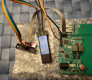
Elektronikaufbau mit ST-Link V2 und Leiterplatte
ST-LINK V2 STM32 Xplorer
in „10W Bitcoin miner mit 450GH/s für Raspberry Pi“ · Projekte & Code · · Platinenfotos
-
PDF
Labornetzteil.pdf
...................................................................................................32 4.6. Gestaltungsvorschlag Frontplatte..................................................................................................................................................................
in „Labornetzgerät als Projekt“ · Analoge Elektronik und Schaltungstechnik ·
-
Datei
GameOfLife.c
#include "GameOfLife.h" #include "main.h" #include "stm32f7xx_hal.h" #include "stm32f7xx_hal_rng.h" uint8_t Layerswitch = 0; void GameOfLife (void) { const uint16_t Spielfeldgroesse_x = 90; const uint16_t Spielfeldgroesse_y = 50; uint8_t Wahrscheinlichkeit
in „Game of Life läuft nur eine Runde!“ · Mikrocontroller und Digitale Elektronik ·
-
 Bild
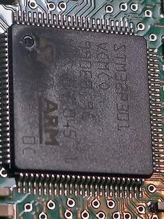
ARM Mikrocontroller auf Leiterplatte
ARM STM32P301 VC MCO 1908 96 0451
in „Def. Mikrocontroller auf Geschirrspüler-Platine?“ · Haus & Smart Home · · Platinenfotos
-
 Bild
Nahaufnahme einer Leiterplatte mit integriertem Schaltkreis
U2 C5 STM32F103 R9
in „fumot 12.000-Puffs Einweg-Vape mit LED-Display“ · Offtopic · · Platinenfotos
-
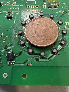
 Bild
Grüne Leiterplatte mit 1-Cent-Münze als Größenvergleich
CABLE, STM32, SWD, JTAG, UART, 1 CENT, 22, 7-0
in „LED Zuleitungen reduzieren.“ · Mikrocontroller und Digitale Elektronik · · Platinenfotos
-
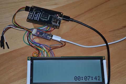
 Bild
Mikrocontroller-Aufbau mit Display und Verkabelung
0.96" TFT STM32H743X 00:07:42
in „Neues Blackboard mit STM32H723“ · Mikrocontroller und Digitale Elektronik · · Fotos
-
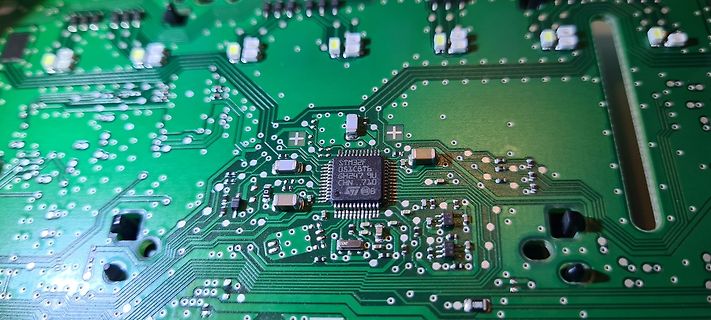
 Bild
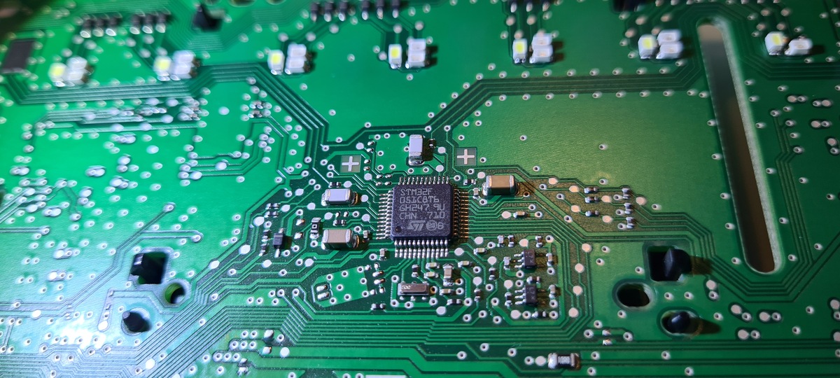
Nahaufnahme einer Leiterplatte mit integriertem Schaltkreis
STM32F 051C8T6 GH24739 CAN F103
in „Bosch Backofen spinnt (HE579GBS6/01)“ · Haus & Smart Home · · Platinenfotos
-
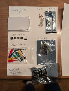
 Bild
Elektronikbauteile und Komponenten auf weißem Papier
NFC-Karten? Photo - Videostunde NE 555 P STM 32 Messklemmen Breadboard Einspeisung
in „Wanderkiste Widlar VII“ · Markt · · Fotos
-
 Bild
Ausschnitt eines Forenbeitrags
Re: Ich verstehe die Forumsoftware nicht. von 🐻 Bernie - Bär (stm32prof) 13.02.2024
in „Ich verstehe die Forumsoftware nicht.“ · www.mikrocontroller.net · · Screenshots
-
 Bild
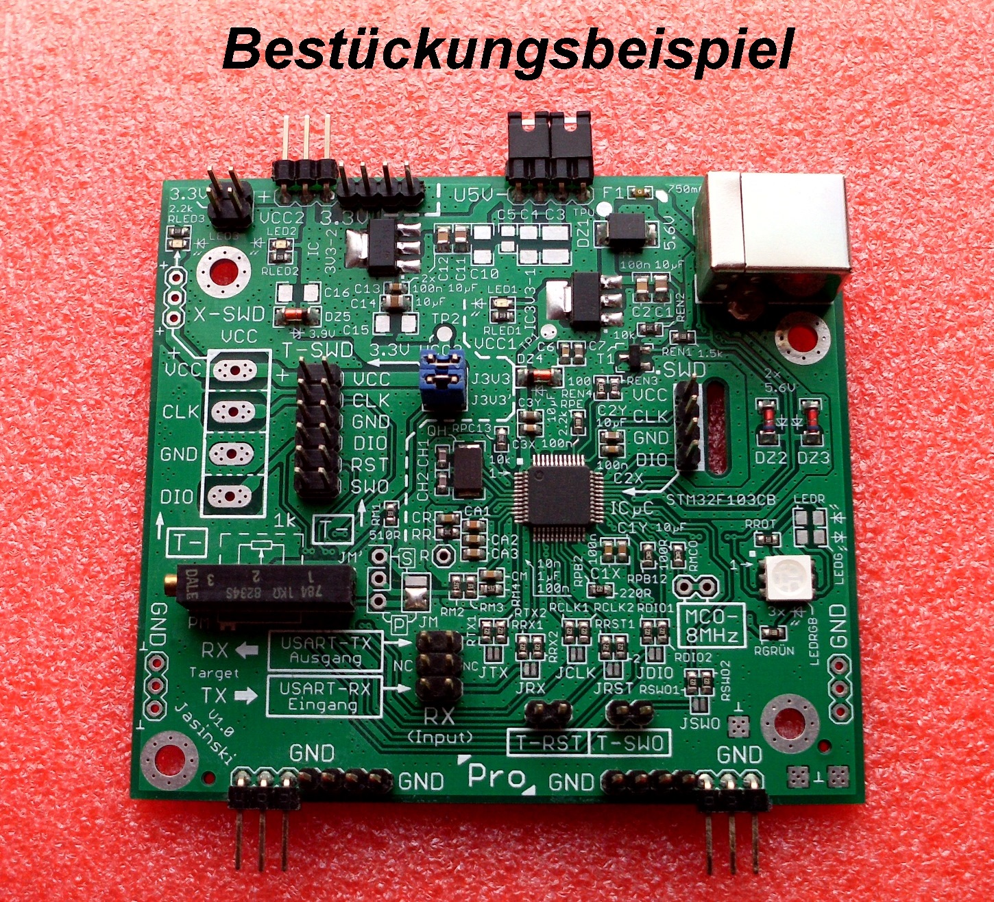
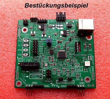
Bestückungsbeispiel einer Mikrocontroller-Platine
Bestückungsbeispiel STM32F103CB UART-TX UART-RX GND VCC SWD JTAG
in „STM32F103C6T6A Lässt sich nicht programmieren“ · Mikrocontroller und Digitale Elektronik · · Platinenfotos
-
Datei
compile_Tasmota_stable_in_docker_container_versuch3.txt
> 1.0 | | |-- <ESP8266WiFi> 1.0 | |-- <ESP8266WiFi> 1.0 |-- <HPMA115S0 Arduino Library> 1.0.0 |-- <stm32_flash> 1.0.0 |-- <BearSSL> 0.6 |-- <universal display Library> 0.1 | |-- <Adafruit GFX Library> 1.5.6 | | |-- <SPI> 1.0 | |-- <SPI> 1.0 | |-- <Wire> 1.0 | |-- <Display renderer> 1.0 | | |-- <Adafruit
in „Dlock 11827 und Tasmota - compilieren für FW-Update“ · Haus & Smart Home ·
-
 Bild
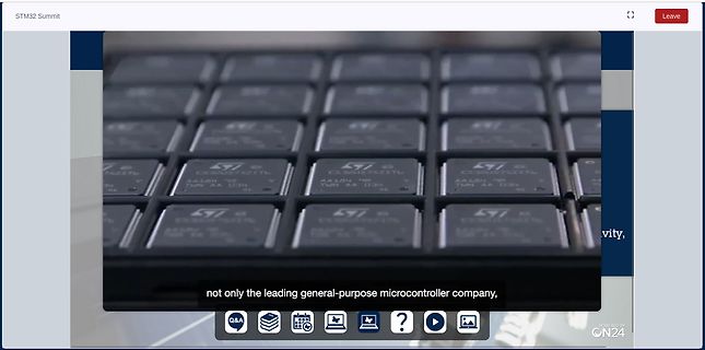
Nahaufnahme von Mikrocontrollern
STM32 Summit Leave not only the leading general-purpose microcontroller company, Q&A ON24
in „STM32 Summit – STMicroelectronics-Onlineevent mit neuer STM32U0-MCU“ · Mikrocontroller und Digitale Elektronik · · Screenshots
-
 Bild
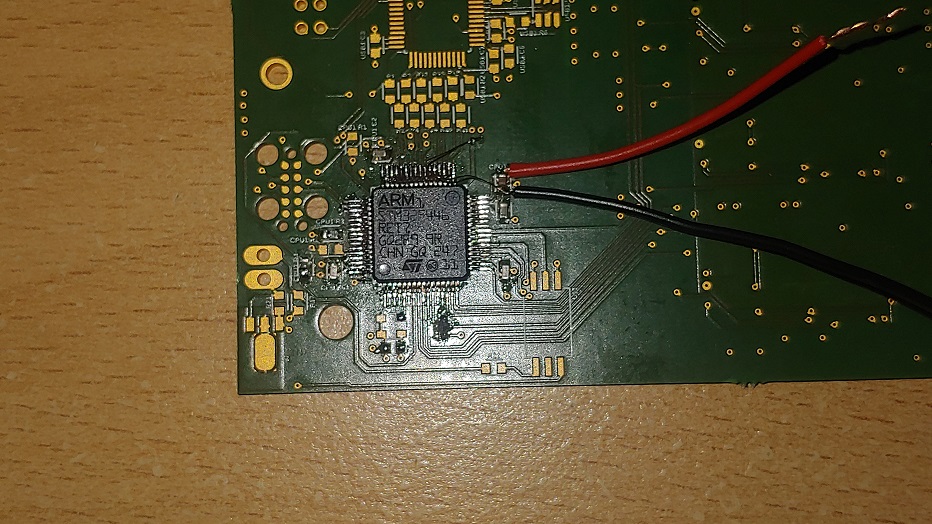
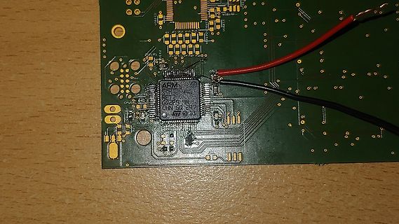
Grüne Leiterplatte mit ARM-Mikrocontroller und Kabeln
ARM STM32F103C8T6 RCT6 64F CHN SQ 247
in „Erbitte Hilfe bei Fehlersuche - STM32F446“ · Mikrocontroller und Digitale Elektronik · · Platinenfotos
-
 Bild
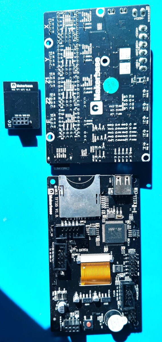
Zwei Makerbase TFT-Leiterplatten auf blauem Grund
Makerbase TFT LCD V1.6, Makerbase TFT35 V1.0, STM32F103, XT_30
in „[V] Diverse Elektronik für 3D-Drucker“ · Markt · · Platinenfotos