valid data through the IRQ pin when it detects a valid touch and needs to report it to the host, so as to improve the efficiency and reduce CPU load. The interrupt edge can be configured as a rising edge or a falling edge as needed. The IRQ pin is also used to wake up the host when matching predefined
this is the address of the first byte of RAM. This program can't be flashed directly with OpenOCD, as OpenOCD doesn't recognize the RAM as such; GDB has to be used as explained above. When a linker script is used as described in the next chapters (using the NOLOAD attribute), OpenOCD can again be used
meaning as “.arm”, and “.code 16” the same as “.thumb” (although the name is slightly misleading, as T32 instructions can be 32 bit as well). There is also “.type Label, %object” to declare some label refers to
directory of this software component. * If no LICENSE file comes with this software, it is provided AS-IS. * ****************************************************************************** */ /* USER CODE END Header */ /* Includes ------------------------------------------------------------------*/ #include
Disclaimer Attention please! The information describes the type of component and shall not be considered as assured characteristics. Terms of delivery and rights to change design reserved. Due to technical requirements components may contain dangerous substances. For information on the types in question please
NoConverter&campaignid=22232435887&adgroupid=&adid=&gad_source=1&gclid=Cj0KCQjwv_m-BhC4ARIsAIqNeBt9AS_CDn0Z1EKYzXUe2c9IN9GdkouImLCL356yRfX75PBvJUE13ngaAgLEEALw_wcB&gclsrc=aw.ds#fullscreen=show entpuppt sich auf den zweiten Blick gar nicht als USV, sonder als ein DC-Netzteil, um ein Backup über eine
of information for the PIC16F887 microcontroller. These names ; are taken to match the data sheets as closely as possible. ; ; Note that the processor must be selected before this file is included. ; The processor may be selected the following ways: ; ; 1. Command line switch: ; C:\MPASM MYFILE.ASM /
1.18V ▪ Voltage drop over LEDs: 2.88V ▪ LEDs seem to be driven at ~30-40mA -> GPIO is directly driving as current sink. PIR ▪ Device Markings found ▪ GL888 -> This seems to be a sensor with digital interface GL888 PIR output pin ▪ Digital interace 1 2 3 4 5 6 7 8 9 ▪ Pulses seem to repeat in groups of 8
schrieb im Beitrag #7851577: > Für ganz kurze Signale bzw steile Flanken kann man auch ein > 74AS00-Gatter (Advanced Schottky, evtl. mit R-C-Verzögerung vor einem > Eingang für Nadeln) verwenden. Die anderen Gatter zur > Flankenversteilerung vorschalten. 74AS ist ja sowas von flower-power-retro
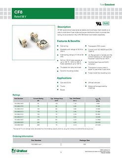
CF8 Rated 58 V Fuse Datasheet
Description
CF 58V automotive fuses serve as battery terminal fuses. Each installs on a pole in a bolt-down fuse holder and power distribution block to provide fast-acting circuit protection. Buy CF8 799 Series fuse holders separately.
Features
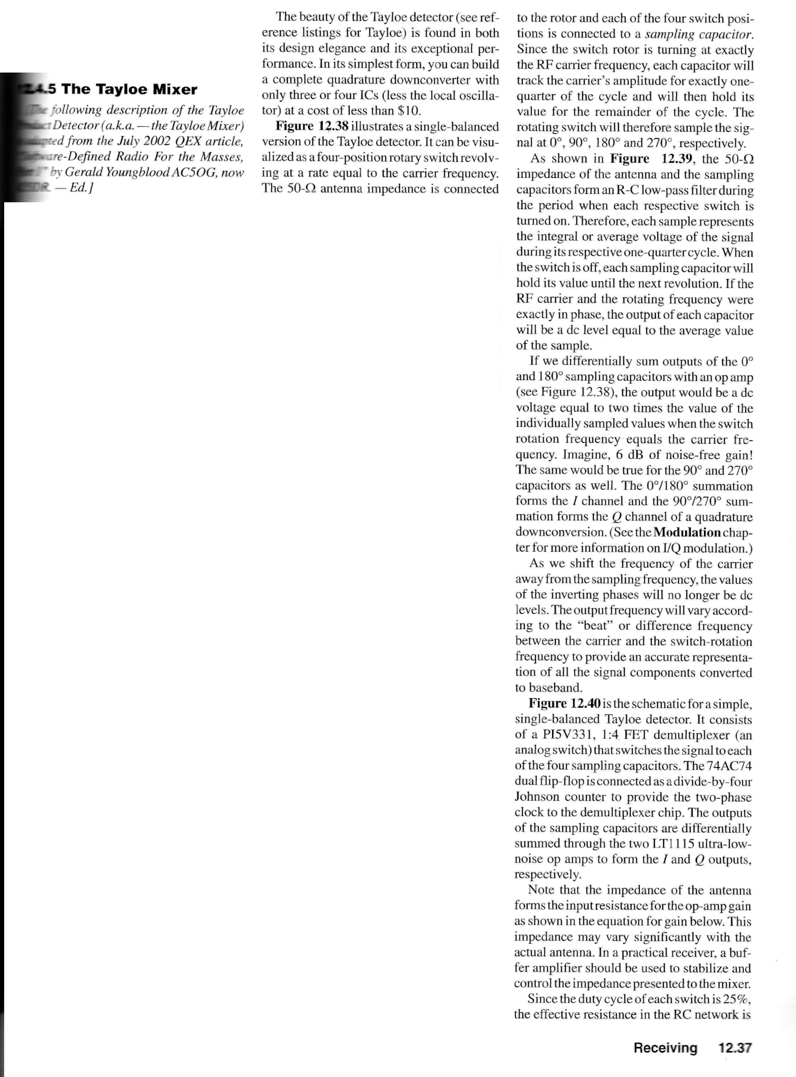
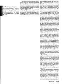
). Figure 12.38 illustrates a single-balanced version of the Tayloe detector. It can be visualized as a four-phase rotation switch revolving at a rate equal to the carrier frequency. The 50-Ω impedance of the antenna and the sampling capacitors form an R-C low-pass filter during the periods when the
frequency applications. The SD211 may be used for a ±5-V analog manufacturingreliability. switching or as a high-speed driver of the SD214. The SD214 is normally used for ±10-V analog switching. These MOSFETs Forsimilarproductssee:quadarray—SD5000/5400series,non-Zener utilize lateral construction to achieve
Das wäre dann auch: [code] sub procedure PWM2_Set_Duty(dim duty as word) duty = word((float(duty) / $FFFF) * 50000) PWM2DCH = Hi(duty) PWM2DCL = Lo(duty) PWM2LD_bit = 1 end sub [/code]
#7849156: > Wieviel RAM hast du denn? https://www.waveshare.com/wiki/ESP32-C6-Zero ESP32-C6FH4 as the main chip, with RISC-V 32-bit single-core processor, support up to 160 MHz, and built-in 320KB ROM, 512KB HP SRAM and 16KB LP SRAM
#7848990: >> ich logge alle 15 Sekunden > > P. Z. schrieb im Beitrag #7849243: >> ESP32-C6FH4 as the main chip, with RISC-V 32-bit single-core processor, >> support up to 160 MHz, and built-in 320KB ROM, 512KB HP SRAM > > Wenn wirklich nur alle 15 Sekunden ein Wegpunkt geschrieben wird, passen
R2 is a very mini- offers a real minimum parts count oscillator. mal leakage term. Note also that as soon as V passes 1 through threshold (about 50 % of supply) and the input to the A SINGLE SCHMITT TRIGGER MAKES AN last inverter begins to change, V 1ill also change in a direc- OSCILLATOR tion that
policy. The previous administration’s policy was focused myopically on climate change, with people as simply collateral damage.” Ich denke die Welt braucht jetzt Energielösungen abseits von Lehrbüchern. Wahrscheinlich bin ich dafür zu alt (komme aus dem letzten Jahrtausend). Sarkasmus oder Verzweiflung
control pin connecting to the MCU. When the pin is pulled HIGH, the data at D[7:0] will be interpreted as data. When the pin is pulled LOW, the data at D[7:0] will be transferred to a command 12 D/C register. In I2C mode, this pin acts as SA0 for slave address selection. When 3-wire serial interface is selected
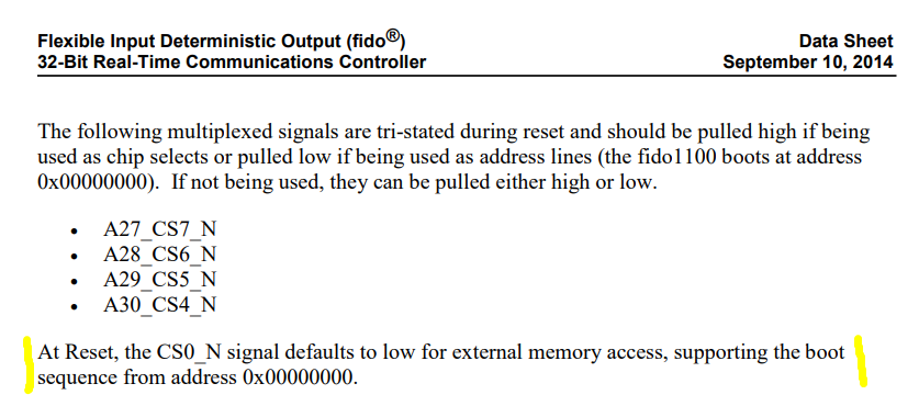
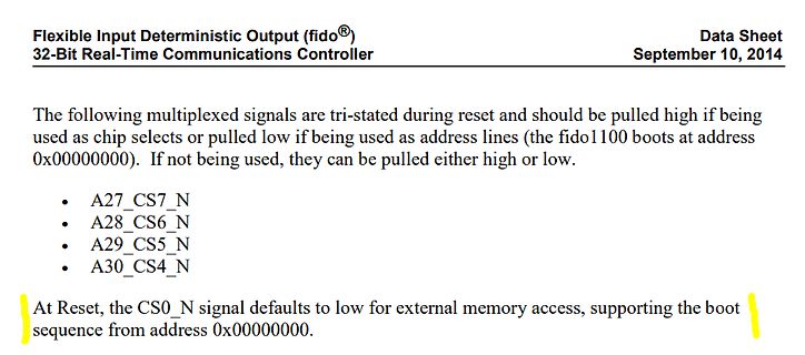
following multiplexed signals are tri-stated during reset and should be pulled high if being used as chip selects or pulled low if being used as address lines (the fido100 boots at address 0x00000000). If not being used, they can be pulled either high or low.
A27_CS7_N
A28_CS6_N
A29_CS5_N
A30_CS4_N
SUSTAINING GRADE" MAY ONLY BE USED IN AUTOMOTIVE APPLICATIONS AT USER’S OWN RISK.RE NOT SPECIFIED AS "AUTOMOTIVE Resale tf ST products with provisions different from the statements and/or technical features set forth in this document shall immediately void liaoility of ST.nted by ST for the ST product
power per package; - 34 - - - - - pF dissipation VI= GND to V CC 1.5 V capacitance [1] pdis the same as PHLand tPLH. [2] tis the same asTHL and TLH. [3] CPD is used to determine the dynamic power dissipatioD (P in W). 2 2 PD = CPD VCC i + (L CC o ) where: i= input frequency in MHz; o = output
to a 1-of-32 (5 to 32 lines) decoder with just four '138 ICs and one inverter. The '138 can be used as an eight output demultiplexer by using one of the active LOW enable inputs as the data input and the remaining enable inputs as strobes. Inputs include clamp diodes. This enables the use of current limiting
whether the Nexperia product is suitable and fit for the customer’s applications and products planned, as well as Product [short] Production This document contains the product data sheet specification. for the planned application and use of customer’s third party customer(s). Customers should provide appropriate
responsibility to determine whether the Nexperia data sheet shall define the specification of the product as agreed between product is suitable and fit for the customer’s applications and Nexperia and its customer, unless Nexperia and products planned, as well as for the planned application and use of customer
package; [3] - 20 - - - - - pF dissipation VI= GND to V CC - 1.5 V capacitance [1] tpdis the same asPHLand tPLH. [2] ttis the same asTHLand TLH. [3] C PDis used to determine the dynamic power dissipatDon (P in μW): 2 2 P D C PD × VCC × i × N + ∑ LC ×CC × o ) where: fi= input frequency in MHz; f = output
1.60 mm [0.063 in.] below body) a. Duty factor = 10%, frequency A 1 kHz, T = 25°C. b. Derate linearly as shown in Figure 4 (deep red), Figure 8 (red), Figure 12 (yellow), and Figure 16 (green). c. Reverse voltage is for LED testing purposes and is not recommended to be used as an application condition.
supply that could be powered on whilCCVis powered off, then the supply current, ICC, will increase as a result. A. Device address is configured as 0100000 for this example. B. P0, P2, and P3 are configured as outputs. C. P1, P4, and P5 are configured as inputs. D. P6 and P7 are not used and must be configured
test gives a visual indication that all dots are functioning properly. Lamp test also may be used as a cursor function or pointer which does not destroy previously displayed characters. Dimming and Blanking the Display Brightness Level BL1 BL0 Blank 0 0 1⁄7 Brightness 0 1 1⁄2 Brightness 1 0 Full Brightness
, as well as to maximize hardware efficiency and circuit simplicity, Philips Semiconductors (now NXP Semiconductors) developed a simple bidirectional 2-wire bus for efficient inter-IC control. This bus is
data line is stable for the duration of the high period of the clock signal. onto the bus is defined as a transmitter and a device receiving data as a receiver. The bus must be The data on the line must be changed during the low controlled by a host device which generates the Serial period of the clock
Programme" liegt). Dritte Lösung wäre die Verwendung einer Verknüpfung, die das Programm via "RunAs" startet. runas /user:Administrator "Pfad\zum\Programm.exe" Wenn das jedesmal nach dem Passwort fragt: "runas /savecred ....". Aber vorher nachlesen und verstehen, was das /savecred bedeutet,
Beitrag #7847731: > Dritte Lösung wäre die Verwendung einer Verknüpfung, die das Programm > via "RunAs" startet. > > runas /user:Administrator "Pfad\zum\Programm.exe" Das ist was anderes als "Ausführen als Administrator". Klingt komisch, ist aber so. Was Du da machst, ist Ausführen in einem anderen
parameters: Sign Parameter Parameter range Unit V DD supply voltage -0.3 to 4.5 V V load voltage, Charging as a power -0.3 to 6 V AT supply pin V SW sampling voltage -0.3 to 4.5 V V Led voltage -0.3 to 4.5 V LED PD Power loss internally limited mW T OPR operating temperature -20 to +125 ℃ T storage temperature
power within the IC is to provide the device with a low resistance to convection heat transfer such as a heat sink. Therefore, it is necessary for the system designer to be conservative in his heat sink calculations. As a rule, the lower the thermal resistance of the heat sink the higher the amount of
oscillator using a junction field-effect transistor (JFET). This circuit will operate on crystal overtones as well as at the fundamental of the crystal, depending on the tuning of the output circuit.[/pre] Irgendwie stehe ich hier auf dem Schlauch: Wie soll denn diese Schaltung schwingen? Da fehlt doch die
connected. Applications All types of resistive, inductive and capacitive • General loads Suitable as LED driver – Inrush current active management by power limitation – Very low standby current Description – 3.0 V CMOS compatible inputs The VN5E016AH-E is a single channel high-side – Optimized electromagnetic
C F 8 04R V Vk2 2 1 C Q ΩK22 1 F 8 Ω ΩK7.2 0 2 B 81D 1 2 R 3 Ω 0 C 3 93R D 1 K K 1 4 1 5181CS2 5101AS2 R 1 3 R 2 R X 21Q 41Q 4 4 1 9 Fu1.0 1 + - 52C Ωk51 C 5 2 2 Ω 1 2 0 0 51Q 54R D R 1 U M A Q 5101AS2 L 2 Ωk7.2 8 1 9 8 1 1 74R 8414N1 62C Ω022 S Q 91D Fp0033 82R 2 D 01 7 1 11 2 6 92R 2 51D Q 5 X 5 Ωk01
gf Fault Sink Current VIN5V; V DS=13V; TjT jsh 10 15 20 mA Single Pulse startingjT=25°C; DD=24V E as VIN5V R gen=R IN MINn330; L=50mH 55 mJ Avalanche Energy (see figures 3 & 4) (*) Pulsed: Pulse duration = 300 s, duty cycle 1.5% 4/14 2 VNS1NV04D PROTECTION FEATURES - OVERTEMPERATURE AND SHORT CIRCUIT
detection The device integrates advanced protective – Output short to V CC detection functions such as load current limitation, inrush – Overload and short to ground (power and overload active management by power limitation) indication limitation, over-temperature shut-off with auto- – Thermal shut-down
+ 26.5V1) + 46.5V2) + 66.5V2) + 86.5V2) 400ms, 2Ω s o 1. All functions of the device are performed as designed after exposure to disturbance. b 2. One or more functions of the device is not performed as designed after exposure and cannot be returned to O proper operation without replacing the device.
transient requirements on V CC pin (part 3) Class Contents C All functions of the device are performed as designed after exposure to disturbance. One or more functions of the device is not performed as designed after exposure to E disturbance and cannot be returned to proper operation without replacing the
transient requirements on V CC pin (part 3) Class Contents C All functions of the device are performed as designed after exposure to disturbance. One or more functions of the device is not performed as designed after E exposure to disturbance and cannot be returned to proper operation without replacing the
a interrupt routine, lighting up one of 24 segments every cycle. the displaybuffer is a 32bit int as binary (24 bit used), containing following (from LSB): 7 bits of second 7 segment digit (ones) 7 bits of first 7 segment digit (tens) 1 bit for flash symbol 1 bit for percent symbol 5 bits for level

 Bild
 Bild
 Bild
 Bild
 Bild