-
Datei
Neuron.vhd
11; --Weight Memory Size DATA_WIDTH : integer := 16; --Float16 Format PAGE_WIDTH : integer := 4; --max. 16 Layers INPUT_WIDTH : integer := 7; --max 128 Input Signals INPUTS : integer := 10; --Number of used inputs MULT_LATENCY : integer := 6; --make shure: Latency < inputs! ADD_LATENCY : integer := 6
in „Pipeline MAC-Unit: Problem mit Latency“ · FPGA, VHDL & Co. ·
-
PDF
RK7Segment-Testsheet.pdf
116 u 117 v 118 w 119x 120 y 121 z 122 { 123 | 124 } 125 ~ 126 127 7 p q r s t u v w x y z { | } ~ € 128 129 ‚ 130 ƒ 131„ 132 … 133 † 134 ‡ 135ˆ 136 ‰ 137 Š 138 ‹ 139 140 Œ 141 Ž 142 143 8 ® b c d ▯ ▯ ▯ ▯ ▯ ¥ ▯ ▯ ▯ 144 ‘ 145 ’ 146 “ 147” 148 • 149 – 150 — 151˜ 152 ™ 153 š 154 › 155 Œ 156 157 ž 158 Ÿ 159
in „S: 7 Segment lookup Table für Buchstaben“ · Softwareentwicklung ·
-
PDF
PCF8574_PRAXIS_Beschaltung_ok_.pdf
Ports 105 - 112 BYTEPORT 14 PCF 8574A 1-0-0 Ports 113 - 120 BYTEPORT 15 PCF 8574A 1-0-1 Ports 121 - 128 BYTEPORT 16 PCF 8574A 1-1-0 Ports 129 - 136 BYTEPORT 17 PCF 8574A 1-1-1 Ports 137 - 144 BYTEPORT 18 Beispiel: DEFINE MYPORT [PORT 34] MYPORT=OFF Damit wird also der Bitport 34 auf LO gesetzt. Dieser
in „pcf 8574 pMos highside driver“ · Mikrocontroller und Digitale Elektronik ·
-
PDF
Impulse_CH17_S.65-67.pdf
gut für diejenigen, die noch Brückenleistung 4 Ohm 342 174 Brückenleistung 4 Ohm – Empfindlichkeit max. mV 221 214 Empfindlichkeit max. mV 275 mehrDruckamWooferbrauchen. Die beiden potenziellen Partner Empfindlichkeit min. V 6,2 5,9 Empfindlichkeit min. V 5,9 THD+N (<22kHz) 5W 0,021 0,096 THD+N (<22kHz
in „SLA-4500 Endstufe Schaltplan gesucht“ · Analoge Elektronik und Schaltungstechnik ·
-
PDF
LPC3130_31.pdf
width Device size External SRAM0 0x2000 0000 0x2000 FFFF 8 bit 64 kB 0x2000 0000 0x2001 FFFF 16 bit 128 kB External SRAM1 0x2002 0000 0x2002 FFFF 8 bit 64 kB 0x2002 0000 0x2003 FFFF 16 bit 128 kB External SDRAM0 0x3000 0000 0x37FF FFFF 16 bit 128 MB 6.7 Internal ROM Memory The internal ROM memory is used
in „LCD-Interface LPC3131“ · Mikrocontroller und Digitale Elektronik ·
-
PDF
AVR-Tutorial.pdf
Potentiometer 10k • 1 HD44780-kompatibles LCD, z.B. 4x20 oder 2x16 Zeichen Teil 6 (Das UART) • 1 Pegelwandler MAX232 oder MAX202 • 5 Elektrolytkondensatoren 22µF • 1 9-polige SUBD-Buchse (female) • 1 dazu passendes Modem(nicht Nullmodem!)-Kabel Software Zuerst braucht man einen Assembler, der in Assemblersprache
in „AVR-Tutorial als PDF bzw *.doc“ · Mikrocontroller und Digitale Elektronik ·
-
PDF
BB_Schem_75839_b.pdf
117 118 B_A25 B_D30 117 118 B_D31 TP5 119 120 reserved by EVB RESET_SW 119 120 125 126 125 126 127 128 127 128 B B QTH-60 QTH-60 GND GND GND GND P5V P5V VCC VCC P5V P5V VCC VCC C14 C15 C16 C17 0.1uF 0.1uF 0.1uF 0.1uF C18 C19 C20 C21 0.1uF 0.1uF 0.1uF 0.1uF GND GND GND GND GND GND GND GND A A Connectors
in „PHILIPS VP5500 VoIP Telefon bei Pollin“ · Mikrocontroller und Digitale Elektronik ·
-
PDF
CS8415A_data.pdf
Symbol Min Max Units High-Level Output VoltOH= -3.2 mA) VOH (VL+) - 1.0 - V Low-Level Output VoltOHe= 3.2 mA) V OL - 0.4 V High-Level Input Voltage, exnept RX VIH 2.0 (VL+) + 0.3 V Low-Level Input Voltage, except RX (Note 5) V -0.3 0.4/0.8 V n IL 5. At 5.0 V mode, VIL 0.8 V (Max), at 3.3 V modeILV =0.4 V (Max). SWITCHING CHARACTERISTICS Inputs: Logic 0 = 0 V, Logic 1 = VL+; C = 20 pF. L Parameter Symbol Min Typ Max Units RST pin Low Pulse Width 200 - - µs PLL Clock Recovery
-
PDF
msp430g2452.pdf
and operating free-air temperature (unless otherwise noted) PARAMETER TEST CONDITIONS V CC MIN TYP MAX UNIT Positive built-in reference VREF+ ≤ 1 mA, REF2_5V = 0 2.2 VCC,REF+ analog supply voltage range V VREF+ ≤ 1 mA, REF2_5V = 1 2.9 I ≤ I max, REF2_5V = 0 1.41 1.5 1.59 VREF+ Positive built-in reference VREF+ VREF+ 3 V V voltage VREF+ ≤ IVREF+max, REF2_5V = 1 2.35 2.5 2.65 I Maximum VREF+ load 3 V ±1 mA LD,VREF+ current VREF+ = 500 µA ± 100 µA, Analog input voltage Ax ≉ 0.75 V, ±2 REF2_5V = 0 VREF+ load regulation 3 V LSB VREF+ = 500 µA ± 100
in „MSP430 Gleitkommazahl in Flash speichern“ · Mikrocontroller und Digitale Elektronik ·
-
PDF
Displayanschluss.pdf
GPIO 10 D3 GPIO3 39 4 11 D4 116 D5 PWM 51 1 JP4 115 PWM 114 D6 113 D7 D8 +3,3V 112 D9 111 D10 107 128 106 D11 CONF 105 D12 D13 104 D14 103 D15 99 D16 98 88 D17 D18 87 D19 92 D20 91 D21 90 89 D22 D23 CS 123 CS A0 122 D/C RD 121 WR 120 E-RD 50 RW/WR TE RESET 127 RESET U1CPU SSD1963 +3,3V U2 MAX-809S-3Volt
-
PDF
PCF7936AS.pdf
No additional battery supply is needed. Data is transmitted • 256 bit EEPROM for user data storage (128 bit) and by modulating the LF field. device configuration/personalization (128 bit) • EEPROM read/write protection features The Security Transponder features secure contactless • 20 years non-volatile
-
PDF
tlc5620.pdf
Zero-scale-error temperature coefficient is given by: ZSETC = [ZSE() – ZSE(T )]/V × 10 /(T – T ). max min ref max min 5. Full-scale error is the deviation from the ideal full-scalref– 1 LSB) with an output load of 10 kΩ. 6. Full-scale-error temperature coefficient is given by: FSETC = maxE) – FSE (min
in „DAC Schieberegister“ · Mikrocontroller und Digitale Elektronik ·
-
PDF
SM8952AC25.PDF
4/8KB flash embedded fosc=16MHz Variable fosc Symbol Parameter Valid Cycle Unit Remarks Min. Typ. Max Min. Typ. Max T LHLL ALE pulse width RD/WRT 115 2xT - 10 nS T AVLL Address Valid to ALE low RD/WRT 43 T - 20 nS T LLAX Address Hold after ALE low RD/WRT 53 T - 10 nS T LLIV ALE low to Valid Instruction
in „SM8952A Programm auslesen von RFID Reader“ · Mikrocontroller und Digitale Elektronik ·
-
PDF
SM8952AC25.pdf
4/8KB flash embedded fosc=16MHz Variable fosc Symbol Parameter Valid Cycle Unit Remarks Min. Typ. Max Min. Typ. Max T LHLL ALE pulse width RD/WRT 115 2xT - 10 nS T AVLL Address Valid to ALE low RD/WRT 43 T - 20 nS T LLAX Address Hold after ALE low RD/WRT 53 T - 10 nS T LLIV ALE low to Valid Instruction
in „Whirlpool-Steuerung Manipulieren / Fernsteuern: Welches Protokoll?“ · Mikrocontroller und Digitale Elektronik ·
-
PDF
ov7620.pdf
U4 U3 U2 U1 U0 Default 1 0 0 0 0 0 0 0 U6-U0: U channel digital output offset adjustment. Range: +128mV ~ -128mV. If register 27 bit 2=0, this register will be updated by internal auto A/D BLC circuit, and write a value to this register with SCCB has no effect. If register 27 bit 2=1, U channel offset
in „wo omnivision kameramodule kaufen“ · Mikrocontroller und Digitale Elektronik ·
-
PDF
STA508.pdf
Table 7. Notes: 1. The following table explains the VLow, VHLgh variation with V VL VLow min VHigh max Unit 2.7 0.7 1.5 V 3.3 0.8 1.7 V 5 0.85 1.85 V Note 2: See relevant Application Note AN1994 Table 8. Logic Truth Table (see fig. 5) TRI-STATE INxA INxB Q1 Q2 Q3 Q4 OUTPUT MODE 0 x x OFF OFF OFF OFF
in „Heimkino ( Harman Hs 250 defekt )“ · Analoge Elektronik und Schaltungstechnik ·
-
PDF
ds_fs200r12pt4_2_2_de-en.pdf
Kollektor-Emitter-Sperrspannung Collector-emitter voltage T vj25°C VCES 1200 V Kollektor-Dauergleichstrom T C 95°C, T vj max 175°C C nom 200 A Continuous DC collector current T C 25°C, T vj max 175°C IC 280 A Periodischer Kollektor-Spitzenstrom Repetitive peak collector current tP= 1 ms ICRM 400 A Gesamt-Verlustleistung Total power dissipation T C 25°C, T vj max 175°C P tot 1000 W Gate-Emitter-Spitzenspannung Gate-emitter peak voltage VGES +/-20 V Charakteristische Werte / Characteristic Values min. typ. max. Kollektor-Emitter-Sättigungsspannung IC= 200 A,
in „IGBT Verlustleistungsberechnung“ · Analoge Elektronik und Schaltungstechnik ·
-
Datei
2_FracNEON.txt
a0,a1,a2,a3 in Q10 125 VMOV Q1,Q5 ;y = b 126 127 VMOV.I32 Q14,#4 ;init sub value = 4 for each pixel 128 VDPL.I32 Q2, R12 ;init single iteration counters = max_iter-1 129 130 LDR R0,Screen_Start ;Screen Start address 131 LDR R1,Hpixels ;Screen Width 132 MOV R1,R1,LSL#2 ;4 Bytes per Pixel 133 MLA R5,R1,
in „Raspberry Pi als "dicker" Mikrocontroller“ · Mikrocontroller und Digitale Elektronik ·
-
PDF
MAX712-MAX713.pdf
to +70°C Dice* kits are available: Order the MAX712EVKIT-DIP for quick MAX712EPE -40°C to +85°C 16 Plastic DIP evaluation of the linear charger, and the MAX713EVKIT- SO to evaluate the switch-mode charger. MAX712ESE -40°C to +85°C 16 Narrow SO MAX712MJE
in „MAX1775_Verständnisproblem“ · Analoge Elektronik und Schaltungstechnik ·
-
PDF
MAX712-MAX713.pdf
to +70°C Dice* kits are available: Order the MAX712EVKIT-DIP for quick MAX712EPE -40°C to +85°C 16 Plastic DIP evaluation of the linear charger, and the MAX713EVKIT- SO to evaluate the switch-mode charger. MAX712ESE -40°C to +85°C 16 Narrow SO MAX712MJE
in „Kurz vorm Verzweifeln“ · Analoge Elektronik und Schaltungstechnik ·
-
PDF
11000.pdf
down to the next integer value. Example: With 2ms timeout selected in MCCSR register Min. Watchdog Max. Watchdog Value of T[5:0] Bits in WDGCR Register (Hex.) Timeout (ms) Timeout (ms) min max 00 1.496 2.048 3F 128 128.552 54/187 ST72321BRx, ST72321BARx ST72321BJx, ST72321BKx WATCHDOG TIMER (Cont’d)
in „Programmierung von ST72F321Bj9“ · Mikrocontroller und Digitale Elektronik ·
-
PDF
er400trs.pdf
optional flow control to and from the host. The Easy- Radio Transceiver can accept and transmit up to 128 bytes of data which it buffers internally before transmitting in an efficient over-air code format. Any other Easy-Radio Transceiver within range that ‘hears’ the transmission will decode the message
in „Datenübertragung mittels ASK“ · Mikrocontroller und Digitale Elektronik ·
-
Datei
mmc.c
MMC_Direction_REG |= (1<<SPI_SS); // chip select auf output // hardware spi: bus clock = idle low, spi clock / 128 , spi master mode SPCR = (1<<SPE)|(1<<MSTR)|(1<<SPR0)|(1<<SPR1); MMC_Write |= (1<<SPI_SS); // chip selet auf high, karte anwaehlen } #if (MMC_MAX_SPEED==TRUE) // ***************************************************************************** static void spi_maxSpeed(){ //SPI Bus auf max Geschwindigkeit SPCR &= ~((1<<SPR0) | (1<<SPR1)); SPSR |= (1<<SPI2X); } #endif // ***************************************************************************** static void
in „MMC SD library FAT16 FAT32 read write“ · Projekte & Code ·
-
Datei
mmc.c
output DDRD |= (1<<4); // chip select auf output // hardware spi: bus clock = idle low, spi clock / 128 , spi master mode SPCR = (1<<SPE)|(1<<MSTR)|(1<<SPR0)|(1<<SPR1); PORTD |= (1<<4); // chip selet auf high, karte anwaehlen } #if (MMC_MAX_SPEED==TRUE) // ***************************************************************************** static void spi_maxSpeed(){ //SPI Bus auf max Geschwindigkeit SPCR &= ~((1<<SPR0) | (1<<SPR1)); SPSR |= (1<<SPI2X); } #endif // ***************************************************************************** static void
in „AVR und großer Speicher“ · Mikrocontroller und Digitale Elektronik ·
-
PDF
LM3404.pdf
4) Limits appearing in boldface type apply over full Operating Temperature Range. Datasheet min/ / max specification limits are guaranteed by design, test, or statistical analysis. L M LM3404 4 0 Symbol Parameter Conditions Min Typ Max Units 4 H SYSTEM PARAMETERS V ON-1 On-time 1 V = 10V, R = 200 kΩ
in „Extreme Störungen LM3404“ · Mikrocontroller und Digitale Elektronik ·
-
Datei
CoolTerm_Capture__FritzAVM_1V8.CoolTermSettings__2026-06-27_08-52-21-633.txt
size: 131072 bytes (128 KiB), LEB size: 126976 bytes [ 4.612434][ T1] ubi0: min./max. I/O unit sizes: 2048/2048, sub-page size 2048 [ 4.620079][ T1] ubi0: VID header offset: 2048 (aligned 2048), data offset: 4096 [ 4.627630
in „FRITZ!Box 7490 Bootloop“ · Mikrocontroller und Digitale Elektronik ·
-
PDF
BTA41-600B-1382474.pdf
temperature capability (T j(max)150 °C) • High voltage capability • Planar passivated for voltage ruggedness and reliability • Insulated tab rated at 2500 V rms 3. Applications • High current / high surge applications • High power
in „Triac BTA41600B defekt nach durchgansprüfung“ · Mikrocontroller und Digitale Elektronik ·
-
Datei
code.txt
Globale Variablen static int TimeBuffer, c, i; static int table[10] = {0, 1, 2, 4, 8, 16, 32, 64, 128, 256}; // ************************************************************************************************ // Hauptmethode void main (void) { // *****************************************************
in „PWM-Problem mit PIC16F627A - ISR zu langsam?!“ · Mikrocontroller und Digitale Elektronik ·
-
PDF
ADNS-3090_DS_S_V1.0_20130514144306.pdf
Motion_Clear W Any 0x13 Frame_Capture R/W 0x00 0x14 SROM_Enable W 0x00 0x15 - 0x18 Reserved 0x19 Frame_Period_Max_Bound Lower R/W 0xE0 0x1a Frame_Period_Max_Bound_Upper R/W 0x2E 0x1b Frame_Period_Min_Bound_Lower R/W 0x7E 0x1c Frame_Period_Min_Bound_Upper R/W 0x0E 0x1d Shutter_Max_Bound_Lower R/W 0x00 0x1e Shutter_Max_Bound_Upper
in „STM32F4: SPI: MISO Flanken zeigen komisches Verhalten“ · Mikrocontroller und Digitale Elektronik ·
-
PDF
ADNS-3090_DS_S_V1.0_20130514144306.pdf
Motion_Clear W Any 0x13 Frame_Capture R/W 0x00 0x14 SROM_Enable W 0x00 0x15 - 0x18 Reserved 0x19 Frame_Period_Max_Bound Lower R/W 0xE0 0x1a Frame_Period_Max_Bound_Upper R/W 0x2E 0x1b Frame_Period_Min_Bound_Lower R/W 0x7E 0x1c Frame_Period_Min_Bound_Upper R/W 0x0E 0x1d Shutter_Max_Bound_Lower R/W 0x00 0x1e Shutter_Max_Bound_Upper
in „STM32F4: Datenübertragung extrem langsam“ · Mikrocontroller und Digitale Elektronik ·
-
PDF
SC7A20-SilanMicroelectronics.pdf
1 -- ms on 工作温度 Topr -- -40 -- +85 °C I²C 控制接口参数(=2.5V, TA=25°C) I²C 标准模式 I²C 快速模式 参 数 符 号 单位 MIN MAX MIN MAX SCL 时钟频率 f(SCL) 0 100 0 400 KHz SCL 时钟低时间 w(SCLL) 4.7 -- 1.3 -- SCL 时钟高时间 t 4.0 -- 0.6 -- us w(SCLH) SDA 建立时间 su(SDA) 250 -- 100 -- ns SDA 数据保持时间 th(SDA) 0.01 3.45 0.01 0.9 us SDA/SCL 上升沿时间
in „Arduino Custom Firmware für Fitness Armband mit NRF52“ · Mikrocontroller und Digitale Elektronik ·
-
Datei
smartctl_mp.txt
- [ATA only] Gets/sets the Automatic Acoustic Management (AAM) feature (if supported). A value of 128 sets the most quiet (slowest) mode and 254 the fastest (loudest) mode, 'off' disables AAM. Devices may support intermediate levels. Values below 128 are de- fined as vendor specific (0) or retired (
in „smartctl Ausgabe für HDs und SSDs - Seek_Error_Rate“ · PC Hard- und Software ·
-
PDF
bom-v1-0.pdf
65R41T-2402E 0,43 € 0,43 € U100, U101 2BD6221F-E2, motor driver 7-15V, 1A 699-6746 3,11 € 6,22 € U110 1MAX3221 MAX 3221 ECAE 2,95 € 2,95 € U130 1TSOP31236, IR receiver 36KHz TSOP 31236 0,56 € 0,56 € Y60 116MHz crystal 16,0000-HC49U-S 0,30 € 0,30 € Y61 132768Hz crystal 0,032768-SMD 0,40 € 0,40 € 1BOPLA-E430
in „Universalplatine für STM32, grobe Fehler vor der Herstellung?“ · Mikrocontroller und Digitale Elektronik ·
-
PDF
datasheet-1852825.pdf
B Specification Process s e FUNCTION: Momentary action SOLDERING: Preheating to 100˚C for 45 sec. max. Keep flux flush c CONTACT ARRANGEMENT: SPST, N.O. with top surface of PCB; do not apply to component side of PCB i TERMINALS: PC pins and area where terminals are located. Soldering to 255˚C for 5 sec. max. Clean by brushing on solder surface. Do not clean switch with w Mechanical solvents. S l ACTUATION FORCE: 130 grams, 160 grams, 200 grams, 260 t grams c LIFE EXPECTANCY: 100,000 operations. Packaging
-
PDF
HD61202U.pdf
off, set address, set display start line, read status • Lower power dissipation: during display 2 mW max • Power supply: V : 2.7V~5.5V CC • Liquid crystal display driving voltage: 8V to 16V • CMOS process Ordering Information Type No. Package HD61202UFS 100-pin plastic QFP (FP-100A) HD61202UTE 100-pin
in „seltsames Grafik Display verhalten“ · Mikrocontroller und Digitale Elektronik ·
-
PDF
an721.pdf
of a device to be matched, has been increased by be necessary. the factor r (from Figure 25, Q IN max = r • QIN max ). If the attenuation a is plotted versus the frequency for Impedance inverters will be used for impedance practical cases, one may expect to have curves like the ones transformation.
-
PDF
RTL8111B_8168B_Registers_DataSheet_1.0.pdf
to 0 means that there is a CRC appended at the end of a packet. 15-11 - - Reserved 10-8 MXDMA2, RW Max DMA Burst Size per Tx DMA Burst: This field sets the maximum size of 1, 0 transmit DMA data bursts according to the following table: 000: 16 bytes 001: 32 bytes 010: 64 bytes 011: 128 bytes 100: 256
-
PDF
8XCE558.pdf
in the PSW) will also affect flag – 128 bits in a subset of the internal Main RAM settings. – 128 bits in a subset of the Special Function Registers Notes on instruction set and addressing modes: Register-Indirect Addressing Rn Register R7
in „Gesucht: schnelles 8051-Derivat mit Bootloader“ · Mikrocontroller und Digitale Elektronik ·
-
PDF
HINK-E029A01-0629.pdf
with each panel. 2 Features 296×128 pixels display White reflectance above 43% Contrast ratio above 10:1 Ultra wide viewing angle Ultra low power consumption Pure reflective mode Bi-stable display Commercial temperature range Landscape
in „Sammelbestellung elektronische Preisschilder?“ · Markt ·
-
PDF
tps62933-1.pdf
Incorporated Product Folder Links: TPS62933 TPS62933 www.ti.com SLUSEA4 – JUNE 2021 • K = 0.4 • VIN_MAX = 30 V • SW = 500 kHz • OUT_MAX = 3 A The inductor value is calculated to be 6.94 μH. Choose the nearest standard value of 6.8 μH. This gives a new K value of 0.408. The max HS_LIMITis 5.8 A, the calculated
in „TI Buck TPS62933.“ · Analoge Elektronik und Schaltungstechnik ·
-
Datei
572727.html
<a href="#fn48" class="footnote-ref" id="fnref48" role="doc-noteref"><sup>48</sup></a></p> <h2 id="max-max_y"> Max (max_y) </h2> <p>Softmaker Freeoffice wurde ja schon erwähnt. Momentan gibt es sogar das große Softmaker Office Paket kostenlos, ist aber die Version von 2021. Dennoch sicherlich einen Blick
in „Wirklich nutzbare Alternative zu Word un Excel?“ · PC Hard- und Software ·
-
Datei
keybot.asm
ONE_MS_TIMEOUT = 58 ; One ms timer setup value (at CK/64, 3.6864MHz) ;=== Misc definitions === .equ MAX_BUF_SIZE = 64 ;========================================================================== ; Registers ;========================================================================== ; (M ) = Variable is
in „Assembler Programm von 3.6864 auf 10MHZ“ · Mikrocontroller und Digitale Elektronik ·
-
Datei
main.c
AN0_offset = 185; // 0 -> 255 Offset wert immer nur minimal wert nehmen volatile unsigned int AN0_max = 876; // 0 -> 65535 volatile unsigned short ERG; // 0 -> 65535 ANO entspricht DC volatile unsigned int DC_max = 1010; // 0 -> 65535 volatile unsigned int DC_alt = 0; // 0 -> 65535 volatile unsigned
in „PIC18F Werte frieren irgendwann ein“ · Mikrocontroller und Digitale Elektronik ·
-
PDF
Taiwan-Semiconductor-SMCJ.pdf
Leakage current (V) T VWM (Note 3) (Note 2) (Note 2) (mA) (V) I @V (µA) I V CI PPM R WM PPM (V) MIN. MAX. (A) SMCJ5.0 GDD 6.4 7.3 10 5 1000 164 9.6 SMCJ5.0A GDE 6.4 7 10 5 1000 171 9.2 SMCJ6.0 GDF 6.67 8.15 10 6 1000 138 11.4 SMCJ6.0A GDG 6.67 7.37 10 6 1000 152 10.3 SMCJ6.5 GDH 7.22 8.82 10 6.5 500 128
in „Bezeichnung Diode“ · Analoge Elektronik und Schaltungstechnik ·
-
 Bild
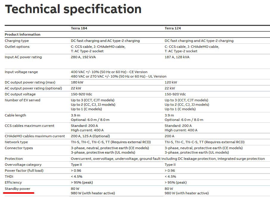
Technische Spezifikation der Terra 184 und Terra 124 Ladestationen
options C: CCS cable, J: CHAdeMO cable, T: AC Type-2 socket Input AC power rating 280 A, 192 kVA 187 A, 128 kVA Input voltage range 400 VAC +/- 10% (50 Hz or 60 Hz) - CE Version 480 VAC or 270 VAC +/- 10% (50 Hz or 60 Hz) - UL Version DC output power rating (max) 180 kW 120 kW AC output power rating (optional
in „Standbyverbrauch Schnelladestation.“ · Haus & Smart Home · · Screenshots
-
Datei
test.asm
5V, Kanal 0 out ADMUX, temp ;ADMUX =Messendekanal auswählen ldi temp, 0b10000100 ;ADC an, CLK=8MHz/128 CLK=8Mhz / 16 TKmin-max=5-20 out ADCSR, temp sei ;Interrupts global aktivieren ;############################################################################ ; Hauptprogrammschleife: loop: sbi ADCSR,
in „Messwert am AD-Wandler schwankt ?“ · Mikrocontroller und Digitale Elektronik ·
-
PDF
ATmega1284P_128KByte.pdf
programming the CKSEL Fuses to “0011” as shown in Table 9-12. (1) Table 9-12. 128kHz Internal Oscillator Operating Modes Nominal frequency CKSEL3..0 128kHz 0011 Note: 1. Note that the 128kHz oscillator is a very low power clock source, and is not designed for high accuracy. When
in „ATmega1284P versus ohne P“ · Mikrocontroller und Digitale Elektronik ·
-
PDF
TDA8425.PDF
and mute control • Power supply with power-on reset QUICK REFERENCE DATA PARAMETER SYMBOL MIN. TYP. MAX. UNIT Supply voltage (pin 4) V CC 10.8 12.0 13.2 V Input signal handling V 2 − − V l Input sensitivity full power at the output stage V − 300 − mV i Signal plus noise-to-noise ratio (S+N)/N − 86 − dB
in „Eingangsspannung beim TDA8425“ · Analoge Elektronik und Schaltungstechnik ·
-
PDF
TDA8425.pdf
and mute control • Power supply with power-on reset QUICK REFERENCE DATA PARAMETER SYMBOL MIN. TYP. MAX. UNIT Supply voltage (pin 4) V CC 10.8 12.0 13.2 V Input signal handling V 2 − − V l Input sensitivity full power at the output stage V − 300 − mV i Signal plus noise-to-noise ratio (S+N)/N − 86 − dB