-
Bild
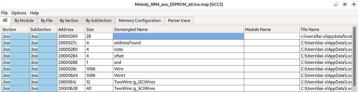
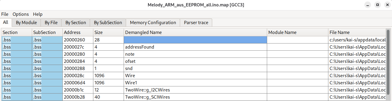
Map-Datei eines Mikrocontroller-Projekts
Melody_ARM_aus_EEPROM_all.ino.map [GCC3] All By Module By File By Section By SubSection Memory Configuration Parser trace Section SubSection Address Size Demangled Name Module Name File Name .bss .bss 20000260 28 .bss .bss 2000027c
in „Arduino Uno R4: Besonderheiten und Abhilfen“ · Mikrocontroller und Digitale Elektronik · · Screenshots
-
Bild
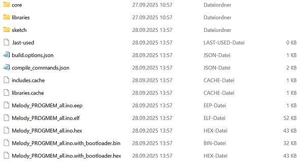
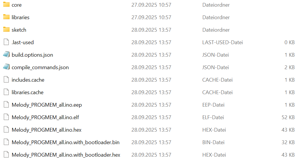
Dateimanager mit Arduino-Build-Dateien
28.09.2025 13:57 CACHE-Datei 1 KB libraries.cache 28.09.2025 13:57 CACHE-Datei 1 KB Melody_PROGMEM_all.ino.eep 28.09.2025 13:57 EEP-Datei 1 KB Melody_PROGMEM_all.ino.elf 28.09.2025 13:57 ELF-Datei 52 KB Melody_PROGMEM_all.ino.hex 28.09.2025 13:57 HEX-Datei 43 KB Melody_PROGMEM_all.ino.with_bootloader.bin 28.09.2025 13:57 BIN-Datei 32 KB Melody_PROGMEM_all.ino.with_bootloader.hex 28.09.2025 13:57 HEX-Datei 43 KB
in „Arduino Uno R4: Besonderheiten und Abhilfen“ · Mikrocontroller und Digitale Elektronik · · Screenshots
-
Datei
sketch_sep28d.ino
#include <Streaming.h> // die Lib findest du selber ;-) Print &cout = Serial; // cout Emulation für "Arme" // constexpr int melody[] // Globale Variablen verwenden 6744 Bytes // int melody[] // Globale Variablen verwenden 7080 Bytes const int melody[] // Globale Variablen verwenden 6744 Bytes { 1,4,6,8,22,5, 1,4,6,8,22,5, 1,4,6,8,22,5, 1,4,6,8,22,5, 1,4,6,8,22,5, 1,4,6,8,22,5, 1,4,6,8,22,5, 1,4,6,8,22,5, 1,4,6,8,22,5, 1,4,6,8,22,5, 1,4,6,8,22,5, 1,4,6,8,22,5, 1,4,6,8,22,5, 1,4,6,8,22,5, }; void setup() { delay(6000); Serial.begin(9600); cout << F("Start: ") << F(__FILE__) << endl; for(auto data: melody
in „Arduino Uno R4: Besonderheiten und Abhilfen“ · Mikrocontroller und Digitale Elektronik ·
-
Bild
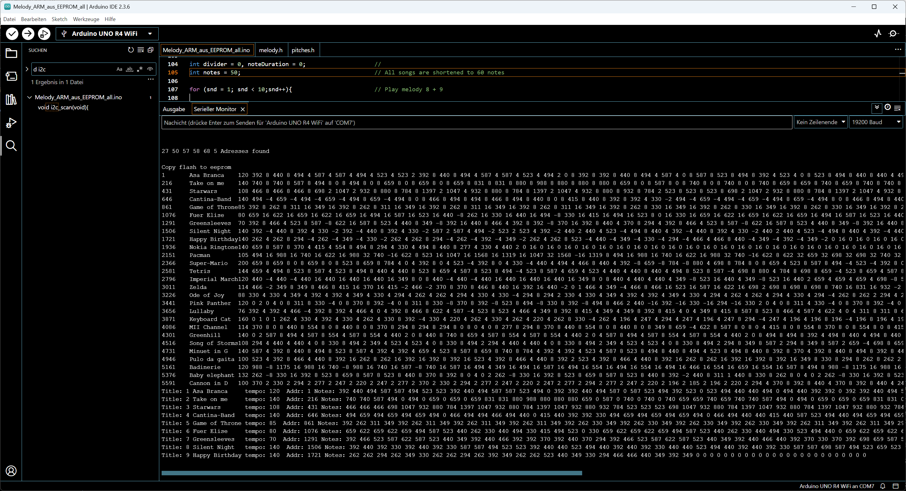
Arduino IDE Code und Serieller Monitor
Melody_ARM_aus_EEPROM_all.ino - Arduino UNO R4 WiFi int divider = 0; int notes = 50; // All songs are shortened to 60 notes for (snd = 1; snd < 10; snd++); // Play melody 8 + 9 Ausgabe Serieller Monitor X Copy flash to eeprom 1
in „Arduino Uno R4: Besonderheiten und Abhilfen“ · Mikrocontroller und Digitale Elektronik · · Screenshots
-
Datei
Melody_ARM_aus_EEPROM_all.ino
// **************************************************** // Melodien aus EEPROM vom 27. 09. 2025 // **************************************************** const /*PROGMEM*/ char title[] = { // List of text for melody-titles new 30.06.2025 - change number_mel too! "Asa Branca " // 1 Asa Branca 0 text-length 14 all titles full length "Take on me " // 2 Take on me "Starwars " // 3 Starwars "Cantina-Band " // 4 Cantina-Band "Game of Throne" // 5 Game of Thrones "Fuer Elise " // 6 Für Elise "Greensleeves " // 7 Greensleeves "Silent Night " // 8 Silent Night "Happy Birthday" // 9 Happy Birthday "Nokia Ringtone
in „Arduino Uno R4: Besonderheiten und Abhilfen“ · Mikrocontroller und Digitale Elektronik ·
-
Datei
Arrduino_R4_Melodien_aus_EEPROM.ino
void melodie(){ // Play melody 1- number mel from external eeprom - new if (snd > 0){ // Melody not stopped ofset = (snd-1) * ((length*4) +15); // Offset = 0*50*2= 0, 1*50*2 = 100 integers! *2 -> *4 int ext_ee_adr = EXT_EE_MELODY_R+1 + ofset; // Address base + offset - ignore first byte which is the data-type - moved to here 26-09-2025 tempo=read_ext_eeprom(ext_ee_adr + 14); // Melody tempo starts at address +14 int wholenote = (60000 * 4) / tempo; // Calculate note (tempo is integer) int divider = 0, noteDuration = 0; // Clear divider and note duration divider=read_integer(ext_ee_adr+15+thisNote
in „Arduino Uno R4: Besonderheiten und Abhilfen“ · Mikrocontroller und Digitale Elektronik ·
-
Datei
Melody_PROGMEM_all.ino
// **************************************************** // Melodien aus PROGMEM vom 27. 09. 2025 // **************************************************** const PROGMEM char title[] = { // List of text for melody-titles new 30.06.2025 - change number_mel too! "Asa Branca " // 1 Asa Branca 0 text-length 14 all titles full length "Take on me " // 2 Take on me "Starwars " // 3 Starwars "Cantina-Band " // 4 Cantina-Band "Game of Throne" // 5 Game of Thrones "Fuer Elise " // 6 Für Elise "Greensleeves " // 7 Greensleeves "Silent Night " // 8 Silent Night "Happy Birthday" // 9 Happy Birthday "Nokia Ringtone
in „Arduino Uno R4: Besonderheiten und Abhilfen“ · Mikrocontroller und Digitale Elektronik ·
-
Thread
Arduino Uno R4: Besonderheiten und Abhilfen
kai-s\AppData\Local\arduino\sketches\E60D65F7750953D07710A2F09EA6D18F\sketch\Melody_ARM_aus_EEPROM_all.ino.cpp.o .rodata._ZL6melody 0x00011ccc 0x4e20 C:\Users\kai-s\AppData\Local\arduino\sketches\E60D65F7750953D07710A2F09EA6D18F\sketch\Melody_ARM_aus_EEPROM_all.ino.cpp.o .rodata.
kai-s\AppData\Local\arduino\sketches\E60D65F7750953D07710A2F09EA6D18F\sketch\Melody_ARM_aus_EEPROM_all.ino.cpp.o und diese: Memory Configuration Name Origin Length Attributes FLASH 0x00004000 0x0003c000 xr RAM 0x20000000
Mikrocontroller und Digitale Elektronik ·Kai · ·206 Antworten
-
Thread
Sinus PWM erzeugen
gemacht: https://github.com/SebiR/ATTiny10_Playground/blob/master/PWM_Sine_Dimmer/PWM_Sine_Dimmer.ino
Mikrocontroller und Digitale Elektronik ·Dietmar B. · ·52 Antworten
-
Datei
sketch_sep21d.ino
#include "util/atomic.h" unsigned long mymillis = 0; int main (void) { const unsigned long eventInterval = 1000; unsigned long previousTime = 0; DDRB |= (1 << PB5); TCCR1B |= (1 << WGM12); // Configure timer 1 for CTC mode TIMSK1 |= (1 << OCIE1A); // Enable CTC interrupt OCR1A = 7999; // Set CTC compare value to 1 Hz at 8 MHz AVR clock , with a prescaler of 256 TCCR1B |= (1 << CS00); // Start timer at F_CPU /256 sei (); // Enable global interrupts while (1) { // Updates frequently unsigned long currentTime; ATOMIC_BLOCK(ATOMIC_RESTORESTATE) currentTime = mymillis; // This is the event if (currentTime
in „Versuch einer Millis Funktion für AVR“ · Mikrocontroller und Digitale Elektronik ·
-
Thread
eine mit 'volatile' erzeugte Variable wird im zweiten C-File ignoriert
gerade auch bemerkt! Dank eines dummen Tippfehlers ist aus meiner beabsichtigten a.c Datei eine ac.ino geworden. Ist mir gerade erst aufgefallen. Nach der Korrektur zeigt sich, dass C das nicht so tut. Also ab jetzt behaupte ich das Gegenteil von eben.
Mikrocontroller und Digitale Elektronik ·Thomas S. · ·43 Antworten
-
Thread
Ansteuern ws2812 mit dem SuperMini ESP32-C3
etwas, aber es soll ohne "lib" sein. Verstehe ich nicht. Wenn der Code unbedingt Bestandteil deiner ino Datei sein soll, dann kopiere die benötigten Teile. Was ist daran so schwer? Meine Vermutung: Du willst (dir selbst) ein eigenes Bauwerk vortäuschen, ohne dafür zu lernen wie es funktioniert. Das
Mikrocontroller und Digitale Elektronik ·Al. K. · ·116 Antworten
-
Datei
PunkteAnzeige.ino
#include "uMuxOutputLib.h" #include "debounce.h" constexpr size_t Id1up=3; constexpr size_t Id1dn=0; constexpr size_t Id2up=2; constexpr size_t Id2dn=1; constexpr size_t incount=4; constexpr bool AN=true; constexpr bool AUS=false; constexpr bool ACTIVE_MUX=true; int pins[8] = {6, 7, 8, 9, 10, 11, 12, 13}; int muxes[4] = {3, 2, 4, 5}; const int inpins[incount] = {A0, A1, A2, A3}; const bool cg[11][7] = { /* 0 */ { /* a */ AN, /* b */ AN, /* c */ AN, /* d */ AN, /* e */ AN, /* f */ AN, /* g */ AUS }, /* 1 */ { /* a */ AUS, /* b */ AN, /* c */ AN, /* d */ AUS, /* e */ AUS, /* f */ AUS, /* g */ AUS
in „7-Segment LEDs ansteuern“ · Mikrocontroller und Digitale Elektronik ·
-
Thread
ESP32-S3 --> ASR-Server
github.com/jahm86/AsyncMQTT_Generic/blob/main/examples/ESP32/FullyFeaturedSSL_ESP32/FullyFeaturedSSL_ESP32.ino
Mikrocontroller und Digitale Elektronik ·D a v i d K. · ·17 Antworten
-
Datei
kc85keyboard_V0.ino
/* KC85 Keyboard changes to make consistent output - "A" is now 0x03 like in my chart - debounce - happiness version 26.07.2025 V0: USB-keyboard function: ********************************************* FOR EASIER FLASHING: pin 9 is inputpullup: wen tied to ground the pro micro does not act like a keyboard ********************************************* * * */ /* * scannumber * * * * */ #include <Keyboard.h> #define Serialbaudrate 115200 #define jumperin 9 // Times, wir bleiben daruntger, weil wir nachher der größe nach abfragen, ob größer als #define TIME_MINIMUM 1000 #define TIME_ZERO 4800//unter 5000
in „Tastatur KC85 mit USB-Anschluss ausrüsten“ · Mikrocontroller und Digitale Elektronik ·
-
Thread
ESP32-CAM mit FT232RL und Win11 " No serial data received." 2025
Wenn Dich das nervt, mach Dir eine neue .ino Datei und pack dort ElegantOTA Lite hinein. Geht beides gut, als Client oder als AP. https://www.mikrocontroller.net/topic/goto_post/7894518
Mikrocontroller und Digitale Elektronik ·Lucas P. · ·22 Antworten
-
Datei
arduinoI2Cbridge.ino
#include <Wire.h> const uint8_t I2C_ADDRESS = 0x58; String inputBuffer = ""; void setupClock8MHz() { pinMode(9, OUTPUT); // Stop Timer1 TCCR1A = 0; TCCR1B = 0; TCNT1 = 0; // Toggle OC1A on compare match TCCR1A = _BV(COM1A0); // Set timer mode to CTC (Clear Timer on Compare Match) with OCR1A as TOP TCCR1B = _BV(WGM12); OCR1A = 0; // Compare value // No prescaling -> timer counts at 16 MHz CPU clock TCCR1B |= _BV(CS10); } void setup() { Wire.begin(); Serial.begin(9600); while (!Serial); Serial.println("Serial-to-I2C bridge. Commands:"); Serial.println("W 0x10 0x1234"); Serial.println("R 0x10"); Serial.println
in „Pollin PMT-Modul“ · Mikrocontroller und Digitale Elektronik ·
-
Datei
FC10_Split_text.ino
/* LICENCE see end of file! */ /* Environemental note The program is created for Arduino/ESP8266 and is tested on WIN10 only! */ /* --->>> READ THIS: <<<--- Developer, don't forget to update the version number here! */ // File main control ---------------------------------------------------------- #pragma once // Use this file only once to avoid redefinition problems class SplitText { /** * @class SplitText * @brief Utility class for identifying start and end indices of "words" * within a text using protected and non-protected delimiters. * * This class is a helper class to OledPrint and processes
in „Flexible SplitText() Klasse (Anfänger)“ · Projekte & Code ·
-
Datei
fermenting-control.ino
/* LICENCE see end of file! */ /* Environemental note The program is created for Arduino/ESP8266 and is tested on WIN10 only! */ /* --->>> READ THIS: <<<--- Developer, don't forget to update the version number here! */ // Values visible in THIS file only! // namespace SelfValues { // static constexpr char FILE_AND_VERSION[] = "00.0025"; // } #ifndef DUMMY // Macro statements ============================================= #ifndef DUMMY // 3rd party includes ------------------------------------------- // 3rd party files #include <Arduino.h> #include <Streaming.h> // For convenient printouts to Serial
in „Flexible SplitText() Klasse (Anfänger)“ · Projekte & Code ·
-
Thread
[S] HKW Elektronik - DCF77 Empfangsmodul EM6 DCF 3V
6602-dcf77-decoder https://github.com/udoklein/dcf77/blob/master/examples/Simple_Clock/Simple_Clock.ino http://www.n4iqt.com/wwv/EM6_wwvbE.pdf https://blog.blinkenlight.net/experiments/dcf77/dcf77-receiver-modules/ hier im Forum: https://www.mikrocontroller.net/topic/487789#6124845 https://www.mikrocontroller.net
Markt ·Engelbert S. · ·5 Antworten
-
Bild
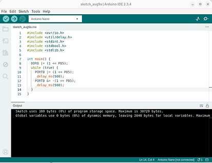
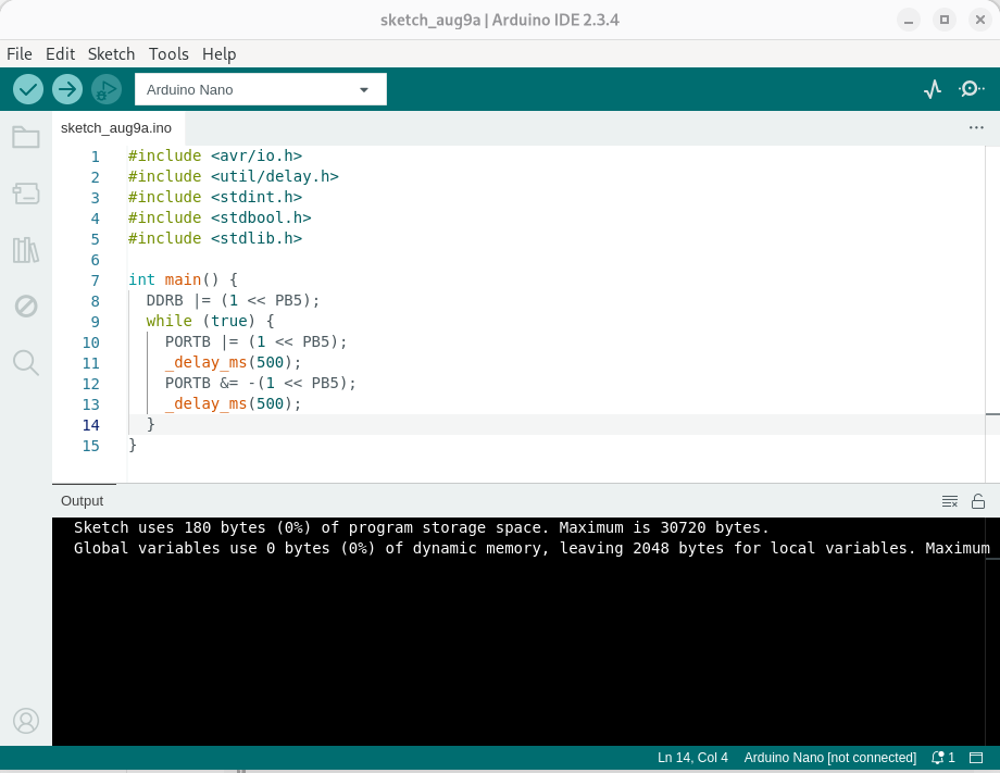
Arduino IDE Code für LED-Blinken
sketch_aug9a | Arduino IDE 2.3.4 File Edit Sketch Tools Help Arduino Nano sketch_aug9a.ino 1 #include <avr/io.h> 2 #include <util/delay.h> 3 #include <stddef.h> 4 #include <stdbool.h> 5 #include <stdlib.h> 6 7 int main() { 8 DDRB |= (1 << PB5); 9 while (true) { 10 PORTB |= (1 << PB5); 11
in „Alarmton/Buzzer-Dreiklang erzeugen“ · Analoge Elektronik und Schaltungstechnik · · Screenshots
-
Datei
Arduino_Zufall_01.ino
long i,j,Summe_1, Summe_2; void setup() { // put your setup code here, to run once: Serial.begin(9600); } void loop() { // put your main code here, to run repeatedly: Summe_2 = 0; for(j = 1; j <= 100000; j++) { Summe_1 = 0; i = 0; while(Summe_1 < 1000000) { Summe_1 = Summe_1 + random(1000001); i = i + 1; } Summe_2 = Summe_2 + i; } Serial.println(Summe_2 / 100000.0, 4); }
in „Physikprojekte“ · Offtopic ·
-
Bild
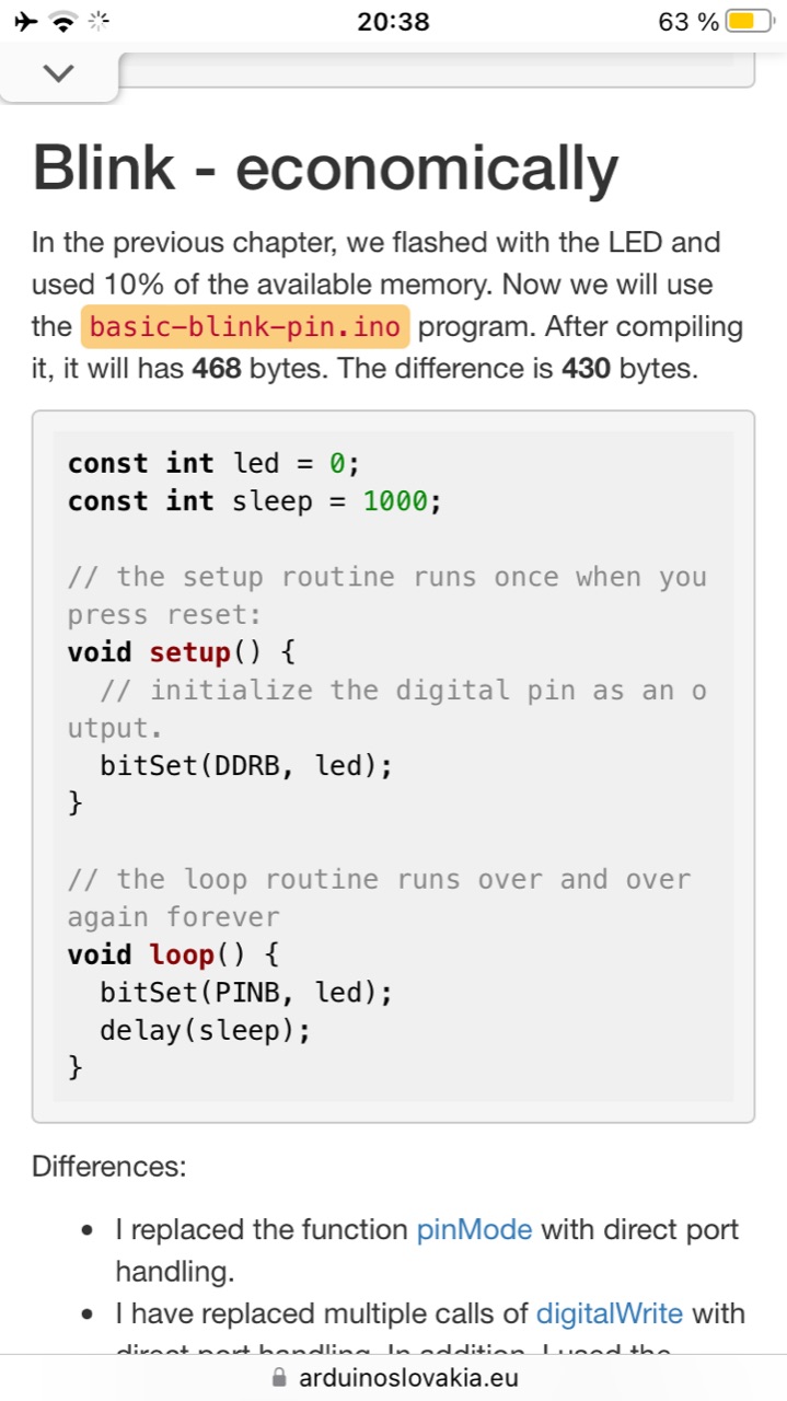
Screenshot eines Programmierbuchs mit Arduino Code
we flashed with the LED and used 10% of the available memory. Now we will use the basic-blink-pin.ino program. After compiling it, it will has 468 bytes. The difference is 430 bytes. const int led = 0; const int sleep = 1000; // the setup routine runs once when you press reset: void setup() { // initialize

in „Alarmton/Buzzer-Dreiklang erzeugen“ · Analoge Elektronik und Schaltungstechnik · · Screenshots
-
Bild
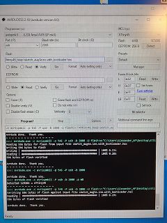
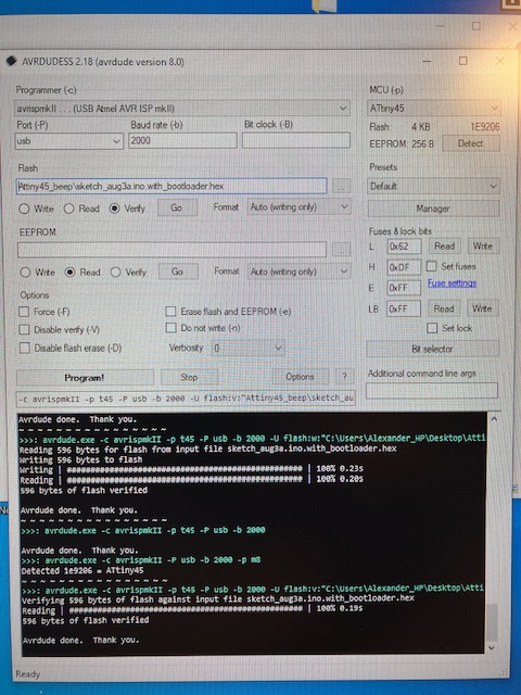
Abfotografierter Bildschirm mit AVRDUDE Software
mkII) Port (P) usb Baud rate (b) 2000 Bit clock (B) Flash 4 KB 1E9206 ATtiny45 Flash sketch_aug3a.ino.with.bootloader.hex EEPROM 256 B MCU (p) ATtiny45 Detected 1E9206 - ATtiny45 >>> avrdude.exe -c avrispmkII -p t45 -P usb -b 2000 -U flash:w:C:\Users\Alexander_HP\Desktop\ATtiny45_sketch_aug3a.ino.with.bootloader.hex
in „Alarmton/Buzzer-Dreiklang erzeugen“ · Analoge Elektronik und Schaltungstechnik · · Fotos
-
Datei
ADXL345_Achsenauslesen.ino
#include <SPI.h> const int CS_PIN = 10; void setup() { Serial.begin(115200); pinMode(CS_PIN, OUTPUT); digitalWrite(CS_PIN, HIGH); SPI.begin(); // SCK = 13, MISO = 12, MOSI = 11 SPI.beginTransaction(SPISettings(5000000, MSBFIRST, SPI_MODE3)); //1 MHz //Device ID lesen (soll 0xE5 sein) uint8_t deviceID = readRegister(0x00); Serial.print("Device ID: 0x"); Serial.println(deviceID, HEX); delay(100); writeRegister(0x31, 0x01); //DATA-Format writeRegister(0x2D, 0x08); // Measurement Mode writeRegister(0x2C, 0x0C); // 400 Hz ODR writeRegister(0x38, 0x00); // FIFO aus } void loop() { // X-, Y-, Z-Daten
in „ADXL380 mit SPI auslesen“ · Mikrocontroller und Digitale Elektronik ·
-
Datei
ESP32_C3_SPI_ADXL380_Analog_Devices.ino
#include <SPI.h> const int CS_PIN = 10; void setup() { Serial.begin(115200); pinMode(CS_PIN, OUTPUT); digitalWrite(CS_PIN, HIGH); SPI.begin(6, 2, 7, 10); // SCK, MISO, MOSI SPI.beginTransaction(SPISettings(6000000, MSBFIRST, SPI_MODE0)); //6 MHz delay(10); //Soft-Reset //writeRegister(0x2A, 0b00000010); writeRegister(0x2A, 0x52); //Seite 69 uint8_t softReset = readRegister(0x2A); Serial.print("Soft-Reset:\t0x"); Serial.print(softReset, HEX); Serial.print("\t0b"); Serial.println(softReset, BIN); delay(10); //NVM Control //writeRegister(0x29, 0b11000000); //delay(10); //Modus-Wahl writeRegister(0x26
in „ADXL380 mit SPI auslesen“ · Mikrocontroller und Digitale Elektronik ·
-
Datei
ESP32_C3_SPI_ADXL380_Analog_Devices.ino
#include <SPI.h> const int CS_PIN = 10; void setup() { Serial.begin(115200); pinMode(CS_PIN, OUTPUT); digitalWrite(CS_PIN, HIGH); SPI.begin(6, 2, 7, 10); // SCK, MISO, MOSI SPI.beginTransaction(SPISettings(1000000, MSBFIRST, SPI_MODE0)); //1 MHz //Soft-Reset writeRegister(0x2A, 0b00000010); uint16_t softReset = readRegister(0x26); Serial.print("Soft-Reset: "); Serial.println(softReset); //Modus-Wahl writeRegister(0x26, 0b00000000); //Standby-Mode uint16_t mode1 = readRegister(0x26); Serial.print("Mode_1: "); Serial.println(mode1); writeRegister(0x27, 0b11100000); //0x27 = DIGITAL ENABLE Reg /
in „ADXL380 mit SPI auslesen“ · Mikrocontroller und Digitale Elektronik ·
-
Datei
ESP32_C3_SPI_ADXL380_Beschleunigungstest.ino
#include <SPI.h> const int CS_PIN = 10; void setup() { Serial.begin(115200); pinMode(CS_PIN, OUTPUT); digitalWrite(CS_PIN, HIGH); // CS auf High, wenn nicht aktiv SPI.begin(6, 2, 7); // SCK, MISO, MOSI SPI.beginTransaction(SPISettings(1000000, MSBFIRST, SPI_MODE0)); // Max. 1 MHz wie empfohlen //Soft-Reset writeRegister(0x2A, 0b00000010); uint16_t softReset = readRegister(0x26); Serial.print("Soft-Reset: "); Serial.println(softReset); //Modus-Wahl writeRegister(0x26, 0b00000000); //Standby-Mode uint16_t mode1 = readRegister(0x26); Serial.print("Mode_1: "); Serial.println(mode1); writeRegister(0x27, 0b11100000
in „ADXL380 mit SPI auslesen“ · Mikrocontroller und Digitale Elektronik ·
-
PDF
243_Moderne_integrierte_Schaltkreise_fuer_Rundfunkempfaenger.pdf
)'p. 6.3 >6.0;lyp.6.-I Klirrfaktoti% filp...50mW < 1,0;lyp.O,2S < 1.0;\)11.0.15 LurlaufventirluIR, inoB typ. 83 Iyp. 84 Eill.pnpwidtrswodin tD I(SI l)'p100 ryp.l80 :2('):- ' = .I~' - ' ~ .::IO := --- Ein.ilIIpr.usdlspoInnUT1liV.... 1)'p.3.0 1)'p.4,O Ra- 10kD. B W .20 ... 20000Hz. Orcnzfreqllcnz( 3dB)
in „UKW-Empfänger/Selbstbauanleitung gesucht“ · HF, Funk und Felder ·
-
Thread
Compileroptionen
Arduino.h:28, from C:\Users\ar\AppData\Local\Temp\arduino_build_25786\sketch\LHM600_11.ino.cpp:1: LHM600_11:35:23: error: expected unqualified-id before 'volatile' static const uint16_t PINK = 0xF81F; ^ LHM600_11:35:23: error: expected ')' before 'volatile'
Mikrocontroller und Digitale Elektronik ·Ralph S. · ·81 Antworten
-
Datei
taschenrechner.ino
#include <MCUFRIEND_kbv.h> #include <Adafruit_GFX.h> #include <TouchScreen.h> #include <avr/wdt.h> #define MINPRESSURE 200 #define MAXPRESSURE 1000 const int XP = 8, XM = A2, YP = A3, YM = 9; const int TS_LEFT = 125, TS_RT = 920, TS_TOP = 948, TS_BOT = 97; TouchScreen ts = TouchScreen(XP, YP, XM, YM, 300); MCUFRIEND_kbv tft; const char* button_labels[5][5] = { {"7", "8", "9", "/", "C"}, {"4", "5", "6", "*", "<-"}, {"1", "2", "3", "-", "("}, {"0", ".", "=", "+", ")"}, {"sqrt", "x^2", "1/x", "%", "+/-"} }; #define ROWS 5 #define COLS 5 int pixel_x, pixel_y; #define STACK_MAX 12 float numStack[STACK_MAX
in „Taschenrechner mit Touchscrenn und Serieller Eingabe auf Arduino Uno gequetscht“ · Projekte & Code ·
-
Datei
Arduino_Geigerzaehler_Poisson_Testgenerator.ino
#include <LiquidCrystal_I2C.h> #include <Wire.h> #include <SPI.h> int outputPin = 2; LiquidCrystal_I2C lcd(0x27,16,2); // set the LCD address to 0x27 for a 16 chars and 2 line display. ACHTUNG: Adresse kann auch 0x3F sein !!! // Anschlüsse: // GND - GND // VCC - 5V // SDA - ANALOG Pin 4 // SCL - ANALOG pin 5 // =========================== // ======= SETUP ========= // =========================== void setup() { Serial.begin(9600); lcd.begin(); // initialize the lcd lcd.backlight(); lcd.setCursor(0,0); lcd.print("Geigerzaehler"); lcd.setCursor(0,1); lcd.print("Generator"); pinMode(outputPin, OUTPUT
in „Physikprojekte“ · Offtopic ·
-
Datei
Arduino_Geigerzaehler_Poisson.ino
#include <LiquidCrystal_I2C.h> #include <Wire.h> #include <SPI.h> #include <SD.h> LiquidCrystal_I2C lcd(0x27,16,2); // set the LCD address to 0x27 for a 16 chars and 2 line display. ACHTUNG: Adresse kann auch 0x3F sein !!! // Anschlüsse: // GND - GND // VCC - 5V // SDA - ANALOG Pin 4 // SCL - ANALOG pin 5 const int buttonPin = 8; int buttonState = 0; const byte interruptPin = 2; int pulse = 0; long time_alt; int seconds; int i; int counts[200]; const int chipSelect = 10; // used for Arduino // =========================== // ======= SETUP ========= // =========================== void setup() {
in „Physikprojekte“ · Offtopic ·
-
Datei
FG_250MHz.ino
/* Taktgenerator fuer RP2040 Pico Pi mit Ausgang an GPIO21. 2025-07-21 Michael Nowak www.mino-elektronik.de */ #include"rp2040_arduino.h" // Registerdefinitionen #define BIT(x) (1<<x) #define DEF_SYSCLOCK 250000000 // default #define MHZ_12 12000000 // default #define MHZ_FAKTOR 1000000 // 1e6 #define REF_DIV 2 #define PLL_DIV1 3 // #define PLL_DIV2 2 // void kurz_warten(void) // fuer kurze Verzoegerungen { volatile int i = 10000; while(i--); } void setup() { // put your setup code here, to run once: VREG_AND_CHIP_RESET_SET-> VREG = 15<<VREG_AND_CHIP_RESET_VREG_VSEL_Pos; while(!(VREG_AND_CHIP_RESET
in „Gesucht Generator/Oszillator mit fester Frequenz 250 MHz“ · Analoge Elektronik und Schaltungstechnik ·
-
Thread
CH32V003 will sich nicht programmieren lassen
C:\Users\49174\AppData\Local\arduino\sketches\76EA383A602CA205D92872EAB89D6453/CH32V003-Blinktest1.ino.elf} verify; wlink_reset_resume; exit;" Open On-Chip Debugger 0.11.0+dev-02415-gfad123a16-dirty (2023-05-05-13:43) Licensed under GNU GPL v2 For bug reports, read http://openocd.org/doc/doxygen
Mikrocontroller und Digitale Elektronik ·LL H. · ·6 Antworten
-
Datei
10.split_text.058.ino
/* LICENCE see end of file! */ /* Environemental note The program is created for Arduino/ESP8266 and is tested on WIN10 only! */ /* --->>> READ THIS: <<<--- Developer, don't forget to update the version number in the private section of the class! */ #ifndef DUMMY // Mandatory Preprocessor Items ================================= // Meta items --------------------------------------------------------------- #ifndef _10_SPLIT_TEXT_IS_STANDALONE #define _10_SPLIT_TEXT_IS_STANDALONE true // If running as a standalone #endif // _10_SPLIT_TEXT_IS_STANDALONE // REQUIRED IN GLOBAL SPACE ================
in „Flexible SplitText() Klasse (Anfänger)“ · Projekte & Code ·
-
Bild
C++ Quellcode in einem Texteditor
Projects\Gearbox\Arduino\DS\sketch\escribable_files\10_new2_frame_split_text\10_new2_frame_split_text.ino /* LICENCE see end of file */ #ifndef DUMMY // Mandatory Preprocessor Items #include "shared_includes.h" #include "shared_globals.h" class SplitText { #ifndef DUMMY // private: #ifndef DUMMY // public
in „Flexible SplitText() Klasse (Anfänger)“ · Projekte & Code · · Screenshots
-
Datei
FG_250MHz.ino
/* Taktgenerator fuer RP2040 Pico Pi mit Ausgang an GPIO21. Die Frequenz wird in der Arduino IDE eingestellt: hier 250 MHz. 2025-17-07 Michael Nowak www.mino-elektronik.de */ #include"rp2040_arduino.h" // Registerdefinitionen #define BIT(x) (1<<x) void setup() { // put your setup code here, to run once: CLOCKS->CLK_GPOUT0_CTRL = CLOCKS_CLK_GPOUT0_CTRL_ENABLE_Msk | // enable 6 << CLOCKS_CLK_GPOUT0_CTRL_AUXSRC_Pos; // pll_sys als Quelle IO_BANK0->GPIO21_CTRL = IO_BANK0_GPIO21_CTRL_FUNCSEL_clocks_gpout_0; // fester Ausgang PADS_BANK0->GPIO21 |= 3<<PADS_BANK0_GPIO21_DRIVE_Pos | // hoher Ausgangsstrom
in „Gesucht Generator/Oszillator mit fester Frequenz 250 MHz“ · Analoge Elektronik und Schaltungstechnik ·
-
Thread
Interrupt bei Ampelsteuerung 8086
die man in Debug eintippen mußte. Weitaus bessere Chancen hättest Du mit einen Arduino Sketch (.ino). Dann könnte man sogar kleine LED-Ampeln anschließen und als Kreuzungmodell anordnen.
Mikrocontroller und Digitale Elektronik ·Fred · ·37 Antworten
-
Bild
Arduino IDE Code-Editor und Serieller Monitor
Multi_Clock_Kat_NEC_Send_Big_Mega_2025.ino void add_crc(unsigned long crc) { unsigned long crc = data; Serial.print("CRC: "); Serial.println(crc, HEX); } Serial Monitor Nachricht (Enter um Nachricht für Arduino Mega 2560 auf COM7 zu senden)
in „Arduino: page-write in I2C eeprom verliert sporadisch ein Byte“ · Mikrocontroller und Digitale Elektronik · · Screenshots
-
Bild
Arduino IDE Serienmonitor mit Hexadezimal-Ausgabe
Arduino IDE 2.3.2 Mult_Ka_NEC_Send_Big_Mega_2025.ino Serial Monitor Max buffer fill: 48 0. page-writes: cnt 0 1. page-writes: cnt 4 2. page-writes: cnt 8 3. page-writes: cnt 12 4. page-writes: cnt 16 5. page-writes: cnt 20 6. page-writes: cnt 24 7. page-writes
in „Arduino: page-write in I2C eeprom verliert sporadisch ein Byte“ · Mikrocontroller und Digitale Elektronik · · Screenshots
-
Datei
port_read_filt_irq.ino
const uint8_t MONITOR_MASK = 0b11111111; // Überwache D0–D7 volatile uint16_t ringBuffer[8] = {0xFFFF, 0xFFFF, 0xFFFF, 0xFFFF, 0xFFFF, 0xFFFF, 0xFFFF, 0xFFFF}; volatile uint8_t sum[8] = {16, 16, 16, 16, 16, 16, 16, 16}; volatile bool portDLow = 0b00000000; volatile bool portDHigh = 0b11111111; ISR(TIMER1_COMPA_vect) { uint8_t portValue = PIND & MONITOR_MASK; // z. B. D2–D7 for (uint8_t i = 0; i < 8; i++) { if (!(MONITOR_MASK & (1 << i))) continue; uint8_t newBit = (portValue >> i) & 1; uint8_t oldBit = (ringBuffer[i] & 0x8000) ? 1 : 0; // Ältestes Bit extrahieren (MSB) ringBuffer[i] = (ringBuffer[i
in „24V 1ms Impuls verlängern“ · Analoge Elektronik und Schaltungstechnik ·
-
Datei
defineMAXBUFFER.ino
#define MAXBUFFER 20 // für längstes Kommando auf Serial In // --------------- serial in --------------- if (Serial.available() > 0) { char incomingByte = (char)Serial.read(); if(incomingByte == 13) { // Wenn das Enter ankommt strcpy(serial_in_command, serial_in_buff); memset(&serial_in_buff[0], 0, sizeof(serial_in_buff)); // 30.554 Bytes chr_cnt = 0; } // if(incomingByte == 13) else { // Falls kein Enter kommt muss der Text gespeichert werden in dem inText Array if(isprint(incomingByte)) { if(chr_cnt<(MAXBUFFER-2)) serial_in_buff[chr_cnt++] = incomingByte; else { Serial.println(F("serBUF ov->
in „Arduino: page-write in I2C eeprom verliert sporadisch ein Byte“ · Mikrocontroller und Digitale Elektronik ·
-
Datei
DOGM204_DEMO.ino
#include <Wire.h> #define LCD_ADDR 0x3D // 7-bit Adresse (SA0=VDD) #define RESET_PIN 8 // Zeitvariablen int sekunde = 0, minute = 0, stunde = 0; int tag = 1, monat = 1, jahr = 2025; unsigned long letzteAktualisierung = 0; // Serielle Eingabe String inputBuffer = ""; void lcdCommand(uint8_t cmd, bool cont = false) { Wire.write(cont ? 0x80 : 0x00); // Control Byte: Co=cont, RS=0 Wire.write(cmd); } void lcdData(uint8_t data) { Wire.beginTransmission(LCD_ADDR); Wire.write(0x40); // Control Byte: Co=0, RS=1 Wire.write(data); Wire.endTransmission(); } void setContrast(uint8_t contrast) { // Contrast
in „EA DOGM204 Display Kontrast Regeln“ · Mikrocontroller und Digitale Elektronik ·
-
Thread
CH32V203 programmieren
WCH/tools/openocd/1.0.0/bin/wch-riscv.cfg -c init -c halt -c program {/tmp/arduino_build_205312/nix2.ino.elf} verify; wlink_reset_resume; exit; [/code] und wch-riscvcfg: [code] #interface wlink adapter driver wlinke adapter speed 6000 transport select sdi wlink_set_address 0x00000000
Mikrocontroller und Digitale Elektronik ·Christoph M. · ·19 Antworten
-
Datei
Page-Write-Test.ino
#include <Wire.h> // I2C #define EXT_EE_ADDR 0x50 // I2C address of 1. external eeprom new 15.05.2025 #define EXT_EE_SIZE 32768 // Max address for 32k-eeprom 22.05.2025 #define EXT_EE_LIMIT 30 // Write buffer limit #define EXT_EE_PAGE 64 // Page size #define EXT_EE_MELODY 0 // Melody data start address in external eeprom #define EXT_EE_CALENDAR 5000 // Calendar data start address in external eeprom 02.06.2025 #define EXT_EE_TEST1 12000 // Test-data 1 start address in external eeprom ++++ 18.06.2025 10000 -> 12000 #define EXT_EE_TEST2 17000 // Test-data 2 start address in external eeprom ++++ 15000
in „Arduino: page-write in I2C eeprom verliert sporadisch ein Byte“ · Mikrocontroller und Digitale Elektronik ·
-
Datei
Kai_EEprom_Page_Write_02.ino
// https://www.mikrocontroller.net/topic/578561?reply_to=7895508#7895423 #define EXT_EE_ADDR 0x50 // I2C address of 1. external eeprom new 15.05.2025 #define EXT_EE_SIZE 32768 // Max address for 32k-eeprom 22.05.2025 #define EXT_EE_LIMIT 30 // Write buffer limit #define EXT_EE_PAGE 64 // Page size #define EXT_EE_MELODY 0 // Melody data start address in external eeprom #define EXT_EE_CALENDAR 5000 // Calendar data start address in external eeprom 02.06.2025 #define EXT_EE_TEST1 12000 // Test-data 1 start address in external eeprom ++++ 18.06.2025 10000 -> 12000 #define EXT_EE_TEST2 17000 // Test-data
in „Arduino: page-write in I2C eeprom verliert sporadisch ein Byte“ · Mikrocontroller und Digitale Elektronik ·
-
Datei
Page_Write_Test_ohne_Log.ino
#include <Wire.h> // I2C #define EXT_EE_ADDR 0x50 // I2C address of 1. external eeprom new 15.05.2025 #define EXT_EE_SIZE 32768 // Max address for 32k-eeprom 22.05.2025 #define EXT_EE_LIMIT 30 // Write buffer limit #define EXT_EE_PAGE 64 // Page size #define EXT_EE_MELODY 0 // Melody data start address in external eeprom #define EXT_EE_CALENDAR 5000 // Calendar data start address in external eeprom 02.06.2025 #define EXT_EE_TEST1 12000 // Test-data 1 start address in external eeprom ++++ 18.06.2025 10000 -> 12000 #define EXT_EE_TEST2 17000 // Test-data 2 start address in external eeprom ++++ 15000
in „Arduino: page-write in I2C eeprom verliert sporadisch ein Byte“ · Mikrocontroller und Digitale Elektronik ·
-
Datei
Scannner_Veit.ino
#include <Wire.h> void setup() { Wire.begin(); Serial.begin(9600); Serial.println("\nI2C Scanner"); } void loop() { byte error {255}; byte address {0}; int nDevices {0}; Serial.println("Scanning..."); for(address = 1; address < 78; address++ ) { // The i2c_scanner uses the return value of // the Write.endTransmisstion to see if // a device did acknowledge to the address. Wire.beginTransmission(address); error = Wire.endTransmission(); if (error == 0) { Serial.print("I2C device found at address 0x"); if (address<16) Serial.print("0"); Serial.print(address,HEX); Serial.println(); nDevices++; } else if (error==4) {
in „Arduino: page-write in I2C eeprom verliert sporadisch ein Byte“ · Mikrocontroller und Digitale Elektronik ·
-
Datei
I2C_Adressen_und_Frequenz_Scanner.ino
/* https://evision-webshop.de/blog/i2c-slave-adressierung-mit-7-bit-8-bit-und-10-bit I2C Adressen und Frequenz Scanner */ #include <Streaming.h> #include <Wire.h> Stream &cout {Serial}; TwoWire &wire0 {Wire}; // die echten Frequenzen sind abhängig vom Pullup und Leitungskapazität const uint32_t i2cFreq [] = {100000, 200000, 400000}; // , 800000}; const uint8_t ANZAHLFREQ = sizeof(i2cFreq) / sizeof(i2cFreq[0]); void setup() { Serial.begin(9600); Wire.begin(); cout.println("\nReset ####"); delay(100); scanner(cout, wire0, 0); } void loop (void) { scanner(cout, wire0, 5000); } void scanner (Stream &
in „Arduino: page-write in I2C eeprom verliert sporadisch ein Byte“ · Mikrocontroller und Digitale Elektronik ·