PCA9533 2 4-bit I C-bus LED dimmer Rev. 03 Ñ 27 April 2009 Product data sheet 1. General description The PCA9533 is a 4-bit I C-bus and SMBus I/O expander optimized for dimming LEDs in 256 discrete steps for Red/Green/Blue
PCA9533 2 4-bit I C-bus LED dimmer Rev. 03 Ñ 27 April 2009 Product data sheet 1. General description The PCA9533 is a 4-bit I C-bus and SMBus I/O expander optimized for dimming LEDs in 256 discrete steps for Red/Green/Blue
3.6V 3.5mA @RF only Hardware Working current 17mA @TX 10dBm 45mA @TX 14dBm Working temperature -30C ~105° C Storage temperature -45C ~ 135°C Shape 15mm x 17.3mm x 3mm Encryption type AES 128/192/256 Software Update firmware UART Download Software develop SDK ShenZhen XiaoTeng Technology Co.,Ltd Copyright
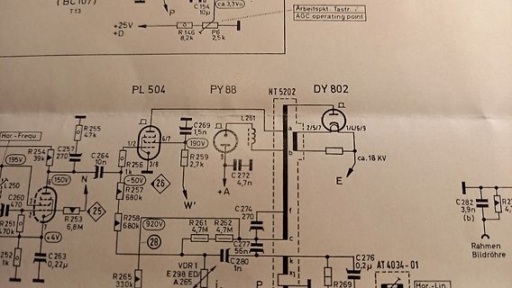
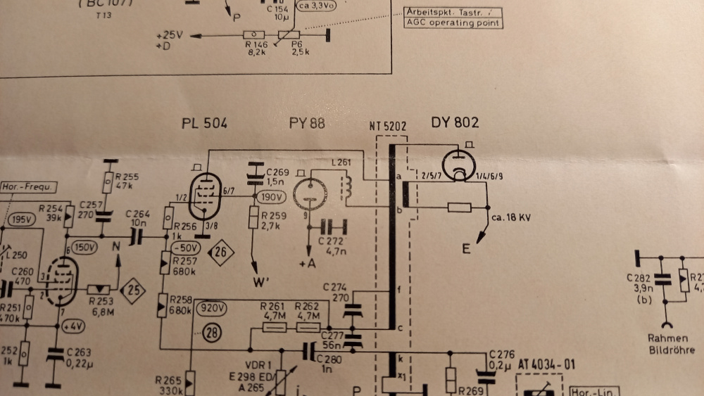
(BC107) T13 +25V D R 146 8,2k P6 2,5k C 154 10u AGC operating point PL 504 PY 88 NT 5202 DY 802 R 255 47k C 257 270 C 264 10n R 256 3/8 6/7 1/4/6/9 R 259 2,7k L 261 C 272 4,7n ca. 18 KV E R 257 680k -50V 26 C 260 470 R 251 10k R 252 1k 253 6,8M 263 0,22u 28 261 R 262 4,7k 265 330k 274 270 277 56n 276 0,2u 280 1n R 269 AT 4034-01 Hor.-Lin.
allereinfachsten diesen mir EINEM Eprom 32k und EINEM Ram 32k abzudecken. Eprom 0000-7FFF Typ 27C256 Ram 8000-FFFF Typ 62256 Da braucht es weder "einen Haufen or-Gates" noch "verschiedene ramchips".
Flash und ein SRAM völlig aus. Z.B.: https://www.digikey.de/de/products/detail/microchip-technology/AT28C256-15PU/1008506 https://www.digikey.de/de/products/detail/renesas-electronics-corporation/71256SA25TPG/1915734 OR-Gatter hatte ich noch nie benötigt. Vielleicht noch Adreßdekoder 74HC139 für
performance. --- via https://www.gigadevice.com/product/mcu/high-performance-mcus/gd32g5xx-series [/c] Zu guter Letzt gibt es im Zusammenspiel mit Beckhoff Neuigkeiten, die das EtherCAT-Portfolio ansprechbar machen: [c] The GDSCN832 series is a 2/3-port EtherCAT® SubDevice Controller integrating
zuvor nicht möglich. Wir gehen von einem sehr moderaten Wachstum aus. [/c]
running at clock speeds up to 20 MHz. They include 32/64 KB of Flash, 4/8 KB of SRAM, and 256 bytes of EEPROM. The microcontrollers are available in 20-, 28-, 32- and 48-pin packages. The family uses our latest
int bestn = -1; int bestpre = -1; int besterr = 0; int errval; for (n = 2; n <= 64; n++) { //Start at 2: we need to be able to set h/l so we have at least one high and one low pulse. //Effectively, this does pre=round((fapb/n)/hz). pre = ((fapb / n) + (hz / 2)) / hz; if (pre <= 0) { pre = 1; } if (pre
672 master slave 28-11 I2C mastereading I2C slaveith a 7-bit Address 674 28-12 I2C mastereading I2C slaveith a 10-bit Address 676 28-13 I2C mastereading N Bytes of Data from addrM of I2C slaveith a 7-bit Address 679 28-
Noise Voltage B = 10Hz to 100KHz TJ = 25°C 100 µV SVR Supply Voltage Rejection ∆V I 10 V f = 120Hz 54 60 dB V d Dropout Voltage IO= 1 A TJ= 25°C ∆V O 100 1.4 V mV I Short Circuit Current 2.1 A sc (*) Load and line regulation are specified at
PCA9533 2 4-bit I C-bus LED dimmer Rev. 03 Ñ 27 April 2009 Product data sheet 1. General description The PCA9533 is a 4-bit I C-bus and SMBus I/O expander optimized for dimming LEDs in 256 discrete steps for Red/Green/Blue
mein Arbeitgeber spendiert und einem halben Kellerraum voll von Computerschrott): Laptop mit USB-C Thunderbold an einem USB-C Hub-Monitor Im der Bastelbude ein No-Name Mini-PC. Vorher stand da ein Tower mit vielen RS232 Schnittstellen.
D3410 von 10/2015 (19.10.2015). Der auch von 2015 https://www.amazon.de/Business-Multimedia-Intel%C2%AECeleron%C2%AE-2x2-60GHz-7007/dp/B0B3DTB3GG wie https://www.intel.de/content/www/de/de/products/sku/90738/intel-celeron-processor-g3900t-2m-cache-2-60-ghz/specifications.html zeigt. https://www.csl-computer.com
tried to follow the example from this forum and I don't know what I do wrong, I can't read the memory at all. I use stm32 cube ide, and when I tried to read memory address 0xC0000000, it shows '????????', not a random hex, even when I tried to write some data, nothing changed. This is my first time
sitzt, inklusive Flash Speicher und Bootloader. Richtig angefangen mit Basteln habe ich dann mit dem AT89C2051. Erst in Assembler, später in C.
Peter D. schrieb im Beitrag #7754804: > Richtig angefangen mit Basteln habe ich dann mit dem AT89C2051. Willkommen im Club. Die Grundlagen habe ich mit Z80 und 8051 gelernt, meine eigenen Konstruktionen begannen jedoch ebenfalls mit AT89C2051. Zum Lernen ist der gar nicht schlecht, weil er vom
672 master slave 28-11 I2C mastereading I2C slaveith a 7-bit Address 674 28-12 I2C mastereading I2C slaveith a 10-bit Address 676 28-13 I2C mastereading N Bytes of Data from addrM of I2C slaveith a 7-bit Address 679 28-
INTEGRATED CIRCUITS 80C51/87C51/80C31 80C51 8-bit microcontroller family 4K/128 OTP/ROM/ROMless low voltage (2.7V–5.5V), low power, high speed (33 MHz) Product specification 2000 Jan 20 Supersedes data of 1999 Apr 01 IC28 Data
0000 ??ERAM_SIZE NUMBER 0000 ??FDATA_SIZE NUMBER 0000 ??RAM_SIZE NUMBER 0100 ??VERSION NUMBER 0120 ??_AT89C2051_ NUMBER 001B ??_AT89C4051_ NUMBER 001C ??_AT89C51ED2_ NUMBER 0026 ??_AT89C51IC2_ NUMBER 0024 ??_AT89C51ID2_ NUMBER 0025 ??_AT89C51RB2_ NUMBER 0021 ??_AT89C51RC2_ NUMBER 0022 ??_AT89C51RC_ NUMBER 0020 ??_AT89C51RD2_ NUMBER 0023 ??_AT89C51_ NUMBER 001D ??_AT89C52_ NUMBER 001E ??_AT89C55WD_ NUMBER 001F ??_AT89LP2052_ NUMBER 0001 ??_AT89LP213_ NUMBER 0003 ??_AT89LP214_ NUMBER 0004 ??_AT89LP216_ NUMBER 0005
Läßt sich die Firmware des AT89C2051 auslesen oder sind die Lock Bits gesetzt? Falls sich die Firmware auslesen läßt stelle sie hier rein, dann kann man schauen wie die UART Kommunikation abläuft.
nebenbei noch Platz für sehr viele zusätzliche Befehle, wie dunkler, heller, EIN/AUS etc. Da die µC sehr wenig Speicherplatz haben, ist das Programm vermutlich in Assembler geschrieben und man muss auch beim SRAM auf den Verbrauch achten (musste ich damals auch, ich habe aber den AT89C4051 genommen
ANS 1523-0005 Lithium-Thionylchlorid Batterie ER26500 / C Maße Ø 26,5 mm Höhe 50 mm 3,6Volt ??
interface. https://www.eevblog.com/forum/repair/quick-repair-project-marconi-2024/?all da wird ein AT28C256 erwähnt, kann aber sein, dass es dabei um den 2025 geht. Und ein Level2-Passwort, wie man es herausfindet (2025?) Hier ein Foto der Rückseite, aber ohne Batteriehalterung: https://www.rigpix.com
PCA9533 2 4-bit I C-bus LED dimmer Rev. 03 Ñ 27 April 2009 Product data sheet 1. General description The PCA9533 is a 4-bit I C-bus and SMBus I/O expander optimized for dimming LEDs in 256 discrete steps for Red/Green/Blue
******* ; ; file register declarations: uses only registers in bank0 ; bank 0 file registers begin at 0x0c in the 16F84 ; and at 0x20 in the 16F628 ; ;******************************************************************* cblock RAMStart ; ; Floating Point Stack and other locations used by FP.TXT ; ; FP
Bardware-Ausführung (farblich gekennzeichnete Anschlußbuchsen) lw 355 m + s m 355 M + s LR355p/w M355C/G U355SN LE355at&~ IZ355svyR 254582 _. 254819.. 254Ba.. 249 516 .. 2m 517 .. 1 a49 652 .. x x x x x x 249663.. x x 249 8aß.. x x 249 823 .. x x BG. 23648407 x x x x x x 1 PL 3m 237 659 _. x x x 1 HEIDENHAIN
− °C A G001 A G002 Figure 1. Figure 2. 6 Submit Documentation Feedback PCM1801 www.ti.com SBAS131C–OCTOBER 2000–REVISED JULY 2007 TYPICAL PERFORMANCE CURVES (continued) All specifications at A = 25°C, V DD
fertigen lassen. Unterschiede zur Originalplatine sind nur der Speicherchip. Ich verwende einen AS6C62256 (Datasheet:https://www.mouser.at/datasheet/2/12/AS6C62256_23_March_2016_rev1_2-1288423.pdf) statt des BS62LV256PIP55. Nach dem Einschalten scheint die Platine auch zu funktionieren, aber beim
werden. Hallo Harald, bitte nicht falsch verstehen: Ich möchte nicht eine Platine mit 16MHz W65C02-System aufbauen, sondern ich habe hier eine Platine die eben mit den angegebenen Bausteinen wie CPU, VIA, F-Gatter SRAM BS62LV256PIP55 einwandfrei läuft. Den Schaltplan habe ich durch Ausmessen der
Beckenwasser und Raumtemperatur sowie der Nutzung des Schwimmbades ab. Raumtemperatur Wassertemperatur 20 °C 24 °C 28 °C 2 2 2 23 °C 90 W/m 165 W/m 265 W/m 25 °C 65 W/m 2 140 W/m 2 240 W/m 2 28 °C 2 2 2 20 W/m 100 W/m 195 W/m Subject to change and error 28/327 Version 11/2021 Tab. 1.6: Anhaltswerte für den
× A and v = W, moreover the relation ∇ (ϕv) = v ∇ϕ + ϕ∇ v, (3.27) with ϕ = c∇ A and v = W, the inner product has the form W [∇ × (c∇ × A) − ∇(c∇ A)]dΩ Ω = c∇ × A ∇ × W dΩ + c∇ A∇ W dΩ (3.28) Ω Ω + [(c∇ × A) × W] ndΓ − c∇ A(W n)dΓ. Γ Γ Let us next determine the following inner
PCA9533 2 4-bit I C-bus LED dimmer Rev. 03 Ñ 27 April 2009 Product data sheet 1. General description The PCA9533 is a 4-bit I C-bus and SMBus I/O expander optimized for dimming LEDs in 256 discrete steps for Red/Green/Blue

 Bild
Bild