Suchergebnisse für "ESP32-C5"
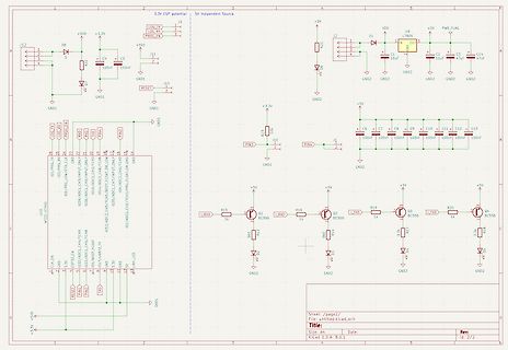
C 3 2 3 C 4 1 1 3 FG Vo-5 1uF -VIN -VO 1uF GND GND GND B B C C D D TITLE: Energie REV: 1.0 Company: Your Company Sheet: 1/1 Date: 2025-07-06 Drawn By: DocRaven 1 2 3 4 5 1 2 3 4 5 ESP 32 -DEVKIT-V1-30PIN COPY 00.2 COPY A 1 A U3 U7 D16 KH-2.54FH-1X15P-H8.5 KH-2.5 D1141X15P-H8.5 ESP und Kn▯öpfe schalten paralell die LED und Projektoren. 1 EN ESP 32 D15 SS14 1 2 VP EN D23 D14 15 12 2 3 VN VP D22 T13 14 11 3 D34 VN TX0 RX0 13 D2 D19 4 4 D34 RX0 12 12 D314 SS14
in
„Schaltplan hilfe“
·
Mikrocontroller und Digitale Elektronik
·
24.07.2025 14:16
639 // maximum buffer for received bytes #define polynom 0x1021 // x16 + x12 + x5 + 1 0x1021 unsigned int year = 0; byte month = 0; int day = 0; int years=0; byte hour = 0; byte minute =0; byte second =0; int ShowProtocolTime = 0; uint32 _t timestamp = 0; uint32 _t timeDummy = 0; uint32
in
„DTZ541 mMe Datenlogger mit ESP (WEB-Sicht)“
·
Mikrocontroller und Digitale Elektronik
·
26.06.2021 16:55
Power 5 V ESP 32 GND 9 +3V3 3 1 D 38 GND 2 GND N GND 37 GND 3 3V3 G IO23 36 EN 4 EN IO22 35 GND SENSOR_VP TXD0 RXD +5 V_EXT 5 SENSOR_VN RXD0 34 TXD 100nF 22uF 6 IO34 IO21 33 7 IO35 NC 32 4 2 1 3 IO32 8 IO32 IO19
in
„ESD32 + USB-C - Welche Bauteile müssen zusammen sein“
·
Platinen
·
10.02.2024 08:35
1 2 3 4 5 6 USB & MCU Spannungsversorgung Senosren A A File: USB & MCU.kicad_sch File: Spannungsversorgung.kicad_sch File:Sensoren.kicad_sch B B C C Sheet: / D D File: ESP 32 _PCB_D3.kicad_sch Title: Size: A4 Date: Rev: KiCad E.D.A. 9.0.6 Id: 1/4 1 2 3 4 5 6 1 2 3 4 5 6 IC1 ESP 32 -C 6-MINI-1-H8 J1 R2 1 32 UJ20-C -H-G-SMT-5 -P16-TR +3.3V GND_1 NC_4 5 .1 þÿk© 2 GND_2 NC_5 33 R1 A1 B5 3 34 GND_1 CC2 3V3 NC_6 A 5 .1 þÿk© VBUS A4 VBUS_1 DP2 B6 4 NC_1 NC_7 35 A A5
in
„Elektroschaltplan für Platine so funktionsfähig“
·
Platinen
·
10.11.2025 20:39
Filename Sheet Date: 20.09.2020 USB & Power.SchDoc 1 / 3 1 2 3 4 1 2 3 4 3V3 3V3 3V3 3V3 C 11 C 12 C 13 C 14 47µ 1µ 100n R12 CO1 A P0 PI P2 P1k PC11PI12 A CC2 CO3 CO1 CO2 S11 SW-PB GP0 GPI GNP P CO1 KMR231G LFS PS0 PI12 3V3 MOD11 ESP 32 WROOM-32 D D11 TLMS1100 GND 3V3 P CD COOD1 R13 P P1k CO3 1 GND
in
„Pflanzensensor Akkulaufzeit“
·
Mikrocontroller und Digitale Elektronik
·
17.02.2023 09:37
1 2 3 4 5 6 USB & MCU Spannungsversorgung Senosren A A File: USB & MCU.kicad_sch File: Spannungsversorgung.kicad_sch File:Sensoren.kicad_sch B B C C Sheet: / D D File: ESP 32 _PCB_D3.kicad_sch Title: Size: A4 Date: Rev: KiCad E.D.A. 9.0.6 Id: 1/4 1 2 3 4 5 6 1 2 3 4 5 6 IC4 ESP 32 -C 6-MINI-1-H8 J2 R2 1 32 UJ20-C -H-G-SMT-5 -P16-TR +3.3V GND_1 NC_4 5 .1 þÿk© 2 GND_2 NC_5 33 R1 A1 B5 3 34 GND_1 CC2 3V3 NC_6 A 5 .1 þÿk© VBUS A4 VBUS_1 DP2 B6 4 NC_1 NC_7 35 A A5
in
„Elektroschaltplan für Platine so funktionsfähig“
·
Platinen
·
09.11.2025 21:26
MCU-ESP 32 -S3 35 SPID D D3/A3 4 11 D10/A10/MOSI 2 GPIO3 SPID GPIO4_D3/A3 GPIO9_D10/A10/MOSI VBUS C D3/A3 9 GPIO4 SPIQ 34 SPIQ D4/A4/I2C _SDA 5 10 D9/A9/MISO A4/B9/VBUS GND D4/A4/I2C _SDA 10 33 SPICLK GPIO5 _D4/A4/I2C _SDA GPIO8_D9/A9/MISO GND R1 5 .1K GPIO5 SPICLK A5 /CC1 B8/SBU2 USB_D- D5 /A5 /I2C _SCL 11 32 SPICS0 D5 /A5 /I2C _SCL 6 GPIO6_D5 /A5 /I2C _SCL GPIO7_D8/A8/SCK 9 D8/A8/SCK USB_D+ A6/DP1 B7/DN2 USB_D+ R3 22R ESP _USB_D
in
„Leiterplatte auf Leiterplatte löten ?“
·
Platinen
·
05.05.2025 20:23
#include <esp _now.h> #include <WiFi.h> #include <esp _wifi.h> // REPLACE WITH THE MAC Address of your receiver uint8_t broadcastAddress[] = {0x3C ,0x61,0x05,0x30,0x9C ,0xD4}; //anzupassen!!! uint8_t newMACAddress[] = {0x3C ,0x61,0x05,0x32 ,0x22,0x4C }; //anzupassen!!! // Variable to store if sending data was successful String success; //Structure example to send data //Must match the receiver structure typedef struct struct_message
in
„ESPnow sendet nur die ersten 32 Bit“
·
Mikrocontroller und Digitale Elektronik
·
04.12.2021 09:28
disabled></p>"; s += "<p><label>Zählername:</label><br><input type=\"text\" name=\"mmen\" maxlength=\"32 \" value=\""; s += c DTZ.getNameDTZ(); s += "\" required></p>"; s += "<p><label>Nutzer:</label><br><input type=\"text\" name=\"user\" maxlength=\"32 \" value=\""; s += c DTZ.getUser(); s += "\" required>
in
„Digitale Stromzähler auslesen und in DB speichern“
·
Mikrocontroller und Digitale Elektronik
·
19.02.2022 21:49
disabled></p>"; s += "<p><label>Zählername:</label><br><input type=\"text\" name=\"mmen\" maxlength=\"32 \" value=\""; s += c DTZ.getNameDTZ(); s += "\" required></p>"; s += "<p><label>Nutzer:</label><br><input type=\"text\" name=\"user\" maxlength=\"32 \" value=\""; s += c DTZ.getUser(); s += "\" required>
in
„DTZ541 mMe Datenlogger mit ESP (WEB-Sicht)“
·
Mikrocontroller und Digitale Elektronik
·
28.08.2021 22:26
disabled></p>"; s += "<p><label>Zählername:</label><br><input type=\"text\" name=\"mmen\" maxlength=\"32 \" value=\""; s += c DTZ.getNameDTZ(); s += "\" required></p>"; s += "<p><label>Nutzer:</label><br><input type=\"text\" name=\"user\" maxlength=\"32 \" value=\""; s += c DTZ.getUser(); s += "\" required>
in
„DTZ541 mMe Datenlogger mit ESP (WEB-Sicht)“
·
Mikrocontroller und Digitale Elektronik
·
28.08.2021 22:33
/** * DTZ 541 Logger **/ #include <ESP 8266WiFi.h> //ESP 8266 Core WiFi Library #include <ESP 8266WiFiMulti.h> //ESP 8266 Core WiFi Library #include <DNSServer.h> #include <ESP 8266WebServer.h> //Local WebServer #include <NTPClient.h> #include
in
„DTZ541 mMe Datenlogger mit ESP (WEB-Sicht)“
·
Mikrocontroller und Digitale Elektronik
·
21.11.2020 20:22
Part15.247 TEST REPORT FCC ID: 2ADUIESP-12 Product Name: WIFI Module Trademark: AI-THINKER Model Number: ESP -12, ESP Prepared For : Shenzhen Anxinke technology co., LTD 5 A,B Building,Gushu WanLiHua Industrial,XiXiang Town, Address: BaoAn District,ShenZhen,China Prepared By : Shenzhen BCTC Technology Co., Ltd
in
„Wlan2Serial Modul für 5 euro“
·
Mikrocontroller und Digitale Elektronik
·
10.01.2015 04:30
send_buffer[96] = {0}; volatile uint8_t counter = 0; volatile uint8_t number_chars = 0; volatile bool ESP _complete = false; volatile bool start = false; char int_buffer[30] = {0}; char ESP _buffer[30] = {0}; const void * tx_buffer_Pointer = &send_buffer[0]; tm *info; bool set_time = false; char Buffer[32
in
„Probleme mit dem DMA beim xMega32A4“
·
Mikrocontroller und Digitale Elektronik
·
25.10.2016 23:30
ABBILDUNG 1: Systemübersicht Nordic WLAN "Shockburst" 2.4 GHz \|/ \|/ | | +---------+ +-----------+ | ESP 8266 | | NRF24LE1E | +---------+ +-----------+ ^ ^ | | | +----------+ | +-----> | GD32 F303 | <-----+ (B) +----------+ (C ) ABBILDUNG 2: Innerer Aufbau "DTU" Nordic "Shockburst" NRF24LE1E 2.4 GHz +----
in
„Wechselrichter Hoymiles HM-xxxx 2,4 GhZ Nordic Protokoll?“
·
Mikrocontroller und Digitale Elektronik
·
16.03.2022 21:04
ABBILDUNG 1: Systemübersicht Nordic WLAN "Shockburst" 2.4 GHz \|/ \|/ | | +---------+ +-----------+ | ESP 8266 | | NRF24LE1E | +---------+ +-----------+ ^ ^ | | | +----------+ | +-----> | GD32 F303 | <-----+ (B) +----------+ (C ) ABBILDUNG 2: Innerer Aufbau "DTU" Nordic "Shockburst" NRF24LE1E 2.4 GHz +----
in
„Wechselrichter Hoymiles HM-xxxx 2,4 GhZ Nordic Protokoll?“
·
Mikrocontroller und Digitale Elektronik
·
16.03.2022 21:07
make STANDALONE=y esp 8266@esp 8266-VirtualBox:~/dev/esp -open-sdk$ make STANDALONE=y make -C crosstool-NG -f ../Makefile _ct-ng make[1]: Verzeichnis »/home/esp 8266/dev/esp -open-sdk/crosstool-NG« wird betreten ./bootstrap Running
in
„EMS > ESP8266-12 WLAN-Modul“
·
Haus & Smart Home
·
15.01.2016 05:45
From 9f7f5 d15cab67326e8c 942aad1143fd9909b5 ff2 Mon Sep 17 00:00:00 2001 From: John-Eric Kamps <johnny86@gmx.de> Date: Fri, 1 Dec 2017 21:53:15 +0100 Subject: [PATCH] First Patch for Frank --- src/display/display.c
in
„WordClock mit WS2812“
·
Projekte & Code
·
01.12.2017 22:07
/** * DTZ 541 Logger * Version 0.9 * 10.12.2020 P. Rebesky **/ #include <ESP 8266WiFi.h> //ESP 8266 Core WiFi Library #include <ESP 8266WiFiMulti.h> //ESP 8266 Core WiFi Library #include <DNSServer.h> #include <ESP 8266WebServer.h> //Local WebServer #include <NTPClient.h> #include
in
„DTZ541 mMe Datenlogger mit ESP (WEB-Sicht)“
·
Mikrocontroller und Digitale Elektronik
·
10.12.2020 21:38
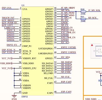
Bild
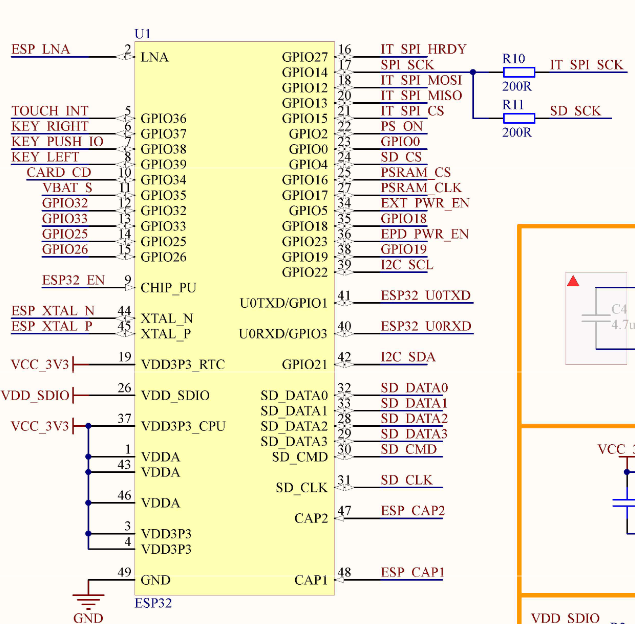
U1 ESP LNA LNA GPIO27 GPIO14 GPIO12 GPIO13 GPIO15 GPIO2 GPIO0 GPIO4 GPIO16 GPIO17 GPIO5 GPIO18 GPIO23 GPIO19 I2C SCK ESP 32 U0TXD U0RXD I2C SDA SD DATA0 SD DATA1 SD DATA2 SD CMD SD CLK ESP CAP2 ESP CAP1 GND
in
„M5Paper: Einschaltverzögerung wie und wo?“
·
Mikrocontroller und Digitale Elektronik
·
17.01.2024 21:59
·
Schaltpläne
", line 3962, in _main main() File "C :\Users\OtisToshiba\.platformio\packages\tool-esptoolpy@1.30000.201119\esptool.py", line 3551, in main esp = chip_class(each_port, initial_baud, args.trace) ^^^^^^^^^^^^^^^^^^^^^^^^^^^^^^^^^^^^^^^^^^^
in
„visual studio 2022 kein boardmanger zu installieren“
·
Mikrocontroller und Digitale Elektronik
·
14.02.2024 13:59
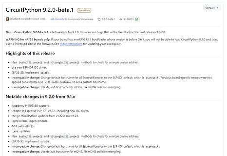
Bild
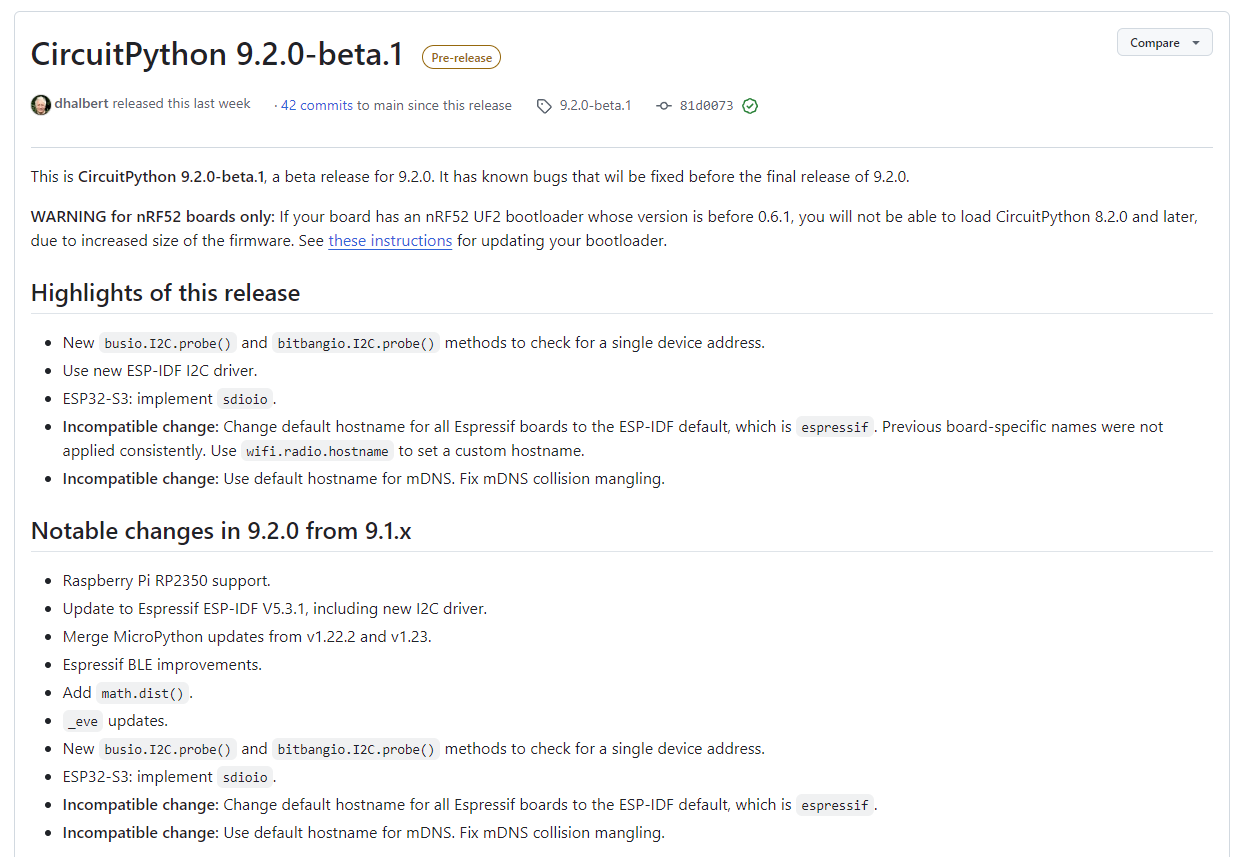
firmware. See these instructions for updating your bootloader.
Highlights of this release
• New busio.I2C .probe() and bitbangio.I2C .probe() methods to check for a single device address.
• Use new ESP -IDF I2C driver.
• ESP 32 -S3: implement sdio.
• Incompatible change: Change default hostname for all Espressif
in
„Python-Updates, C23, Keil MDK und vieles andere mehr“
·
Mikrocontroller und Digitale Elektronik
·
20.10.2024 17:47
·
Screenshots
periodic notifications. The service advertises itself as: 4fafc201-1fb5 -459e-8fcc-c 5 c 9c 331914b And has a characteristic of: beb5483e-36e1-4688-b7f5 -ea07361b26a8 The design of creating the BLE server is: 1. Create a BLE Server 2. Create a BLE Service 3. Create a BLE Characteristic
in
„ESP32 D1 MINI als Bluetooth Master“
·
Mikrocontroller und Digitale Elektronik
·
16.08.2021 10:27
D E EN 1 Q2 B8 N H AO3400A SBU2 G S 1 4 D- 2 1 1 A S D+ 3 6 GND GND GND B 2 B GND +3.3V C C +5 V C 2 C 1 C 6 RN1 100n 22u 22u 1k C 17 D8 5 4 GND U9 GND GND 100n D7 6 3 GND ESP 32 -S2-MINI-2 +5 V GND 3 U1 D6 7 2 GND EN 45 3 39 TXD0 SN75160BDW 0 GND D5 8 1 EN V TXD0 2 GND 3 40 RXD0 DIO4 2 C 19 D4 GPIO0
in
„Sammelbestellung AR488 kompatibler USB-GPIB Adapter. Interesse?“
·
Mikrocontroller und Digitale Elektronik
·
02.01.2025 18:07
Bild
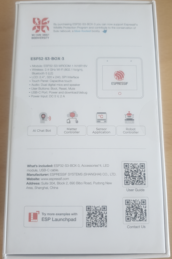
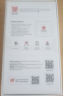
ESP 32 -S3-BOX-3
Module: ESP 32 -S3-WROOM-1-N16R16V
Wireless: 2.4 GHz Wi-Fi (802.11b/g/n), Bluetooth 5 (LE)
LCD: 2.4", 320 x 240, SPI Interface
Touch Panel: Capacitive touch
Audio: Dual digital mics and speaker
User Buttons: Boot, Reset, Mute
USB-C Port: Power and download/debug
Power Input: DC 5 V, 2 A
AI Chat Bot, Matter Controller, Sensor Application, Robot Controller
What's included: ESP 32 -S3-BOX-3, Accessories*4, LED module, USB-C cable.
Manufacturer
in
„[V] Espressif ESP32-S3-Box-3 original verpackt“
·
Markt
·
18.03.2024 10:04
·
Fotos
WiFiManagerParameter custom_field; // global param ( for non blocking w params ) WiFiServer server(80); ESP 8266WiFiMulti WiFiMulti; WiFiUDP ntpUDP; NTPClient timeClient(ntpUDP, "pool.ntp.org", _UTCOFFSET); configDTZ c DTZ; decodeMeter dMETER; meterData mDATA; //*********************** use WIFI manager by Tzapu
in
„Digitale Stromzähler auslesen und in DB speichern“
·
Mikrocontroller und Digitale Elektronik
·
23.11.2022 23:27
GND D5 8 1 ESP 32 -S2-MINI-2 TP3 TP4 0 GND 100n 3 2 EN EN GPIO0 DIO4 2 C 19D4 45 3 39TXD0 B1 C D1 RN2 EN V TXD0 GPIO0 DIO8 3 V 18D8 3 40RXD0 B2 D2 1k GND RXD0 DIO3 4 17D3 GPIO0 4 B3 D3 D4 5 4 IO0 DIO7 5 16D7
in
„Sammelbestellung AR488 kompatibler USB-GPIB Adapter. Interesse?“
·
Mikrocontroller und Digitale Elektronik
·
25.09.2026 17:53
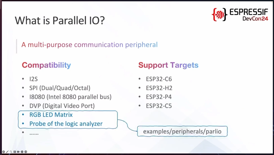
Bild
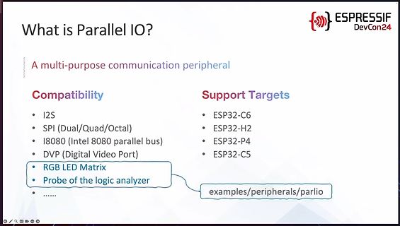
parallel bus)
DVP (Digital Video Port)
RGB LED Matrix
Probe of the logic analyzer
Support Targets
ESP 32 -C 6
ESP 32 -H2
ESP 32 -P4
ESP 32 -C 5
examples/peripherals/parlio
ESPRESSIF DevCon24
in
„Made by Developers, Made For Developers – ESP32 DevCon, Tag 1“
·
Mikrocontroller und Digitale Elektronik
·
03.09.2024 22:31
·
Screenshots
disabled></p>"; s += "<p><label>Zählername:</label><br><input type=\"text\" name=\"mmen\" maxlength=\"32 \" value=\""; s += c DTZ.getNameDTZ(); s += "\" required></p>"; s += "<p><label>Nutzer:</label><br><input type=\"text\" name=\"user\" maxlength=\"32 \" value=\""; s += c DTZ.getUser(); s += "\" required>
in
„Digitale Stromzähler auslesen und in DB speichern“
·
Mikrocontroller und Digitale Elektronik
·
14.05.2022 17:47
''' ESP 32 sender for BME280 Communication Method: ESPNOW external library ttps://github.com/robert-hh/BME280 2026-01-26 mchris ''' peer = b'\xcc\x7b\x5 c \x1e\xac\x5 c ' # MAC address of receiver ESP 32 import network import espnow from machine import Pin, I2C import time import struct from bme280_float import * import re i2c = I2C (1, scl=Pin(22), sda=Pin(21), freq=100000) bme280 = BME280(i2c =i2c ) led = Pin(2, Pin.OUT) # ESP 32 WROOM Pin2 led.on() # A WLAN interface
in
„Micropython Wetterstation“
·
Projekte & Code
·
26.01.2026 15:50
Bild
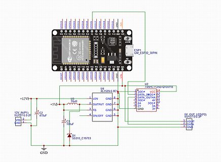
, GPIO04, GPIO02, GPIO15, GND, 3V3, ESP 1, GM_ESP 32 _30PIN, N0, VIN, GND, GPIO13, GPIO12, GPIO14, GPIO27, GPIO26, GPIO25, GPIO33, GPIO32 , GPIO35, GPIO39, GPIO36, GPIO0, RESET, U2 74AHC125D-Q100118, U4 XL5015-5 .0E1, 12V IN(P1) WJ127-5 .0-2F, VIN, GND, +12V, +5 V, C 2 470uF, U3 10uH, C 3 100uF, FB, ON/OFF, D1 SS310_C 19703, 5 V OUT LED(P2) WJ127-5 .0-3P, VOUT, DATA, GND
in
„Benötige Hilfe bei meinem Schaltplan“
·
Analoge Elektronik und Schaltungstechnik
·
30.04.2025 14:14
·
Schaltpläne
Bluetooth #include <BLEDevice.h> #include <BLEServer.h> #include <BLE2902.h> #include <functional> // ESP specific functions and handlers #include <queue> // Pointers and structs // C ++ functionalities #include <string> #include <sstream> // ESP specific libraries #include "esp _system.h" #include "soc/rtc.h
in
„ESP32 Interrupts“
·
Mikrocontroller und Digitale Elektronik
·
29.01.2019 10:32
= i2c _cmd_link_create(); if(i2c _master_start(cmd) != ESP _OK ) { failed |= 1; ESP _LOGI("I2C ", "i2c _master_start failed"); } if(i2c _master_write_byte(cmd, address | I2C _MASTER_WRITE, ACK_CHECK_EN) != ESP _OK
in
„ESP32 IDFv3 Ethernet-Phy KSZ8863 funktioniert nicht“
·
Mikrocontroller und Digitale Elektronik
·
06.09.2024 18:34
0,10 € 0,20 € C 23 11µF KEM X5 R0805 1,0U 0,07 € 0,07 € C 24 110nF X7R-G0805 10N 0,04 € 0,04 € C 25 1470nF KEM X7R0805 470N 0,07 € 0,07 € C 130 14.7µF KEM X5 R0805 4,7U 0,10 € 0,10 € C 66 04.7µF only for STM32 F4, F7 or H7 KEM X5 R0805 4,7U 0,10 € 0,00 € C 71 04.7µF only for STM32 H7 KEM X5 R0805 4,7U 0,10 € 0,00 € C 67, C 68 222pF KEM C 0G0805 22P 0,04 € 0,08 € C 69, C 70 24,7pF NPO-G0805 4,7P 0,04 € 0,08 € C 120, C 121 2100µF 1206 X5 R-G1206
in
„Universalplatine für STM32, grobe Fehler vor der Herstellung?“
·
Mikrocontroller und Digitale Elektronik
·
21.07.2021 19:07
#include <ESP 8266HTTPUpdateServer.h> #include <ESP 8266mDNS.h> #include <ArduinoOTA.h> #include <ESP 8266WiFi.h> #include <DNSServer.h> #include <ESP 8266WebServer.h> #include <PubSubClient.h> #include <WiFiManager.h
in
„Siedle In-Home-Bus Protokoll“
·
Haus & Smart Home
·
08.03.2018 19:00
Bild
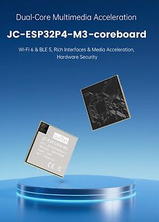
Dual-Core Multimedia Acceleration
JC-ESP 32 P4-M3-coreboard
Wi-Fi 6 & BLE 5 , Rich Interfaces & Media Acceleration, Hardware Security
Guimton
JC-ESP 32 P4-M3
SOC: ESP 32 P4NRW32
Memory: 32 M PSRAM
Flash: 16M
WIFI: ESP 32 -C 6
CE
in
„Satelliten-Arduino, CircuitPython 10 im Betastadium, News vom ESP32-P4 uvam“
·
Mikrocontroller und Digitale Elektronik
·
21.07.2025 22:45
·
Fotos
Bild
3.3V ESP , 5 V Indivend Source, J1, LOG_TX, LOG_RX, PROG_EN, +5 V, D8, D, C 4, 100nF, C 5 , 100nF, J11, GND, RESET, J3, GND, PIN3, PIN4, C 6 bis C 13, 100nF, U9 LTC6652, VDD, OUT, PWR_FLAG, C 1, C 2, C 3, 10uF, 47uF, GND2, R15, R16, R19, R20, Q1 BC556, Q2 BC556, Q3 BC556, Q4 BC556, I_RXD, I_TXD, I_TXD, I_RXD, U10 ESP 32 -WROOM, IO35, IO34, IO32 , IO33, IO39, IO36, IO34, IO35, IO32 , IO33, IO39, IO36, IO34, IO35, IO32 , IO33, IO39, IO36, IO34, IO35, IO32 , IO33, IO39, IO36, IO34, IO35, IO32 , IO33, IO39, IO36, IO34, IO35
in
„ESP32 Max485 und 6N137 brennt ab“
·
Mikrocontroller und Digitale Elektronik
·
09.07.2025 21:17
·
Schaltpläne
LED_71 LED_72 LED_73 LED_74 LED_75 LED_76 LED_77 LED_78 LED_79 LED_80 SPI U1 B B SINK4 SPI GND ESP -32 S VDD5 VVDD5 V A C 7 C 6 39 A SPI 10uF 100nF 1 GND 38 GND C C SPI 2 GND GND 37 LED_81 LED_82 LED_83 LED_84 LED_85 LED_86 LED_87 LED_88 LED_89 LED_90 LED_91 LED_92 LED_93 LED_94 LED_95 LED_96 VDD3V3 3 3V3 IO23 36 GPIO23 SPI ESP _EN 4 EN IO22 35 SCL C 15 C 14 SINK5 GPIO36 5 SENSOR_VP TXD0 34 R15 470 USB_RXD 100nF 10uF SPI 6 SENSOR_VN RXD0 33 R16 USB_TXD VDD3V3 TIMER_INT 7 IO34 IO21 32 SDA VDD3V3 J1 ALARM_INT 8 IO35 NC 31 GND GND
in
„16x16 LED Word Clock mit ESP32“
·
Projekte & Code
·
30.05.2021 16:34
#include <ESP 8266HTTPUpdateServer.h> #include <ESP 8266mDNS.h> #include <ArduinoOTA.h> #include <ESP 8266WiFi.h> #include <DNSServer.h> #include <ESP 8266WebServer.h> #include <PubSubClient.h> #include <WiFiManager.h
in
„Siedle In-Home-Bus Protokoll“
·
Haus & Smart Home
·
16.03.2018 20:37
/* Bluetooth BLE Keyboard - Deutsches Tastaturlayout (QWERTZ) ESP 32 wird per USB an den Sender-PC angeschlossen und sendet Tastenanschlaege per BLE an den Ziel-Rechner. Benutzung mit minicom (Linux) als Sender: minicom -D /dev/ttyUSB0 Hardware: ESP 32 WROOM Framework
in
„Remote Tastatur“
·
Projekte & Code
·
17.08.2026 17:50
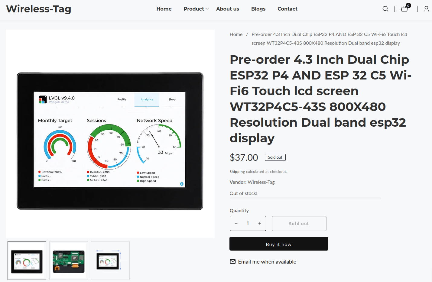
Bild
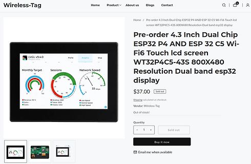
Wireless-Tag Home Product About us Blogs Contact Pre-order 4.3 Inch Dual Chip ESP 32 P4 AND ESP 32 C 5 Wi-Fi6 Touch lcd screen WT32 P4C 5 -43S 800X480 Resolution Dual band esp 32 display $37.00 Sold out Shipping calculated at checkout. Vendor: Wireless-Tag Out of stock! Quantity Sold out
in
„Littelfuse kündigt Mikrocontroller ab, Qualcomm äußert sich zu Arduino uvam“
·
Mikrocontroller und Digitale Elektronik
·
13.10.2026 19:14
·
Screenshots
(5 ) #define MAX_RF_PAYLOAD_SIZE (32 ) #ifdef ESP 8266 #define PACKET_BUFFER_SIZE (30) #else #define PACKET_BUFFER_SIZE (20) #endif // Startup defaults until user reconfigures it #define DEFAULT_RECV_CHANNEL
in
„Wechselrichter Hoymiles HM-xxxx 2,4 GhZ Nordic Protokoll?“
·
Mikrocontroller und Digitale Elektronik
·
11.08.2022 19:57
(5 ) #define MAX_RF_PAYLOAD_SIZE (32 ) #ifdef ESP 8266 #define PACKET_BUFFER_SIZE (30) #else #define PACKET_BUFFER_SIZE (20) #endif // Startup defaults until user reconfigures it #define DEFAULT_RECV_CHANNEL
in
„Wechselrichter Hoymiles HM-xxxx 2,4 GhZ Nordic Protokoll?“
·
Mikrocontroller und Digitale Elektronik
·
13.08.2022 15:36
(5 ) #define MAX_RF_PAYLOAD_SIZE (32 ) #ifdef ESP 8266 #define PACKET_BUFFER_SIZE (30) #else #define PACKET_BUFFER_SIZE (20) #endif // Startup defaults until user reconfigures it #define DEFAULT_RECV_CHANNEL
in
„Wechselrichter Hoymiles HM-xxxx 2,4 GhZ Nordic Protokoll?“
·
Mikrocontroller und Digitale Elektronik
·
08.08.2022 08:53
(5 ) #define MAX_RF_PAYLOAD_SIZE (32 ) #ifdef ESP 8266 #define PACKET_BUFFER_SIZE (30) #else #define PACKET_BUFFER_SIZE (20) #endif // Startup defaults until user reconfigures it #define DEFAULT_RECV_CHANNEL
in
„Wechselrichter Hoymiles HM-xxxx 2,4 GhZ Nordic Protokoll?“
·
Mikrocontroller und Digitale Elektronik
·
11.08.2022 18:36
(5 ) #define MAX_RF_PAYLOAD_SIZE (32 ) #ifdef ESP 8266 #define PACKET_BUFFER_SIZE (30) #else #define PACKET_BUFFER_SIZE (20) #endif // Startup defaults until user reconfigures it #define DEFAULT_RECV_CHANNEL
in
„Wechselrichter Hoymiles HM-xxxx 2,4 GhZ Nordic Protokoll?“
·
Mikrocontroller und Digitale Elektronik
·
11.08.2022 19:44
for more information. Arduino Micro Section common to all radino modules 15 GPIOs HUID Keyboard I²C ATmega32 U4 USB HUID Mouse UART UART MISO,MOSI,SCK for radio communication:served IO8,IO9,D4,D7 SPI-UART bridge WiFi ESP 8266 Radio Section –WiFi In-Circuit GmbH Boltenhagener Str. 124 Document-Nr: 3051000
in
„Wlan2Serial Modul für 5 euro“
·
Mikrocontroller und Digitale Elektronik
·
28.10.2014 15:03
DFIRMWARE_SIZE=503808 -DMCU_RESET_PIN=12 -DMCU_ISP_PIN=13 -DLED_CONN_PIN=0 -DLED_SERIAL_PIN=14 -DVERSION="esp -link stable - 2016-01-13 07:03:51 - development" -DGZIP_COMPRESSION -DCHANGE_TO_STA -c espfs/espfs.c -o build/espfs/espfs.o /mnt/Share/dev/esp -open-sdk/xtensa-lx106-elf/bin/xtensa-lx106-elf-gcc -Imqtt
in
„EMS > ESP8266-12 WLAN-Modul“
·
Haus & Smart Home
·
13.01.2016 07:27
URXD 5 RX P1 P* G A 19 5 71D 7-Segment 1 - D 1 10k R5 GND RA3 6 72A 7-Segment 2 -A ESP 1 ESP PIC R6 Pololu S7V8F3 10k RA4 7 LED2 LED2 R7 100 ESP _INFO 10k GND GND RA5 /SS1 9 72B 7-Segment 2 - B Flash GND GND ICSPDAT
in
„PICKIT3 - Target Halted nach Zuschaltung von Schaltregler“
·
Mikrocontroller und Digitale Elektronik
·
19.12.2017 22:13
(5 ) #define MAX_RF_PAYLOAD_SIZE (32 ) #ifdef ESP 8266 #define PACKET_BUFFER_SIZE (30) #else #define PACKET_BUFFER_SIZE (20) #endif // Startup defaults until user reconfigures it #define DEFAULT_RECV_CHANNEL
in
„Wechselrichter Hoymiles HM-xxxx 2,4 GhZ Nordic Protokoll?“
·
Mikrocontroller und Digitale Elektronik
·
15.08.2022 19:00

 Bild
 Bild
 Bild
 Bild
 Bild
 Bild
 Bild
 Bild