over- and under-shoot 1.02 ⋅70 pF ⋅70000 due to internal comparator response time. R =53,330Ω ⇒ 51kΩ PH Step1:ProgramDead-time Step4:ProgramPreheatTime The dead-time is chosen to be 0.8µs. Using Equation (2) gives the following result: Thepreheattimeof500mssecondswaschosen. Using Equation (8) gives
limit Before EEPIF=1, EEPROM cannot be read EEPIF X V CTK V X SIRC 84 KHz@5V/25℃ 65.5 KHz@5V/25℃ WDT 96ms, 192ms, 768ms,1536ms @5V 125ms, 250ms, 1001ms, 2001 ms @5V WKT 12ms,24ms,48ms,96ms @5V 15.6ms,31.3ms,62.5ms,125ms @5V SFR.RDCTL X V (suggest RDCTL=4ns) OPA V X SFR.OPOF OPOF=0 (POR, CMPP <= OPO) No OPA
Overcharge detection delay time tCU ⎯ 3.2 4.0 4.8 s 2 1 Overcharge timer reset delay time tTR ⎯ 6 12 20 ms 3 1 Overcharge release delay time tCL ⎯ 51 64 77 ms 2 1 CTL pin response time CTL ⎯ ⎯ ⎯ 2.5 ms 4 2 V1=V2=V3=V4=3.5V, Transition time to Test mode TST V ≥V +8.5V ⎯ ⎯ 80 ms 5 3 DD SENSE (2) S-8264AAD,
AMD Athlon , ATI Radeon und ATI FirePro sind Marken von Advanced Micro Devices, Inc. Mic,Windows®,MS-DOS®,Windows Vist, die Windows Vista-Startschaltfläche undlosind Marken oder eingetragene Marken der Microsoft Corporation in den USA und/oder anderen Ländern. Blu-ray Disc ist eine Marke der Blu-ray
At the beginning (t = 0) the voltage across the capacitor cs V (t = 0) = 0.5V. The voltage after 1ms will be calculated, i.e. the time step is ∆t = 1ms. 56 node2 node1 V1 R1 C1 U=2V R=1kΩ C=1µF Figure 6.1: circuit for testing transient analysis First, the MNA matrix has to be built. The three components
Loss [Report of the Transactions Editor-in-Chief]," in IEEE Antennas and Propagation Magazine, vol. 51, no. 2, pp. 166-167, April 2009. [2] Banerjee, Amal. Automated broad and narrow band impedance matching for RF and microwave circuits. Cham, Switzerland: Springer, 2019. [3] White, Joseph F. High frequency
with F = 50 mA, find more info at: www.vishay.com/doc?49650 • Fast proximity: up to 2 m range at 5 ms 4 response time, 3 2 find more info at: www.vishay.com/doc?82741 1 16797 • Supply voltage: 2.0 V to 3.6 V • Material categorization: for definitions of compliance please see www.vishay.com/doc?99912
the module is powered on 1). After the module is powered on, normally it needs about no more than 500ms to 1500ms(depending on the actual track quantities in the storage device) initialization time. Once the initialization is done, the module returns a data to MCU. If it does not return a data after more
frmMain.rbTermAnsi=ANSI frmMain.rbTermHex=HEX frmMain.rbTermCustom=Userdefined: frmMain.chkTermZWms=New line after ms: frmMain.spTermDWHint=Parameter Data Translation frmMain.btnTermSend=Send frmMain.btnTermSendHint=Send text to COM Port frmMain.chkTermBreak=BREAK frmMain.chkTermCR=CR frmMain.chkTermLF=LF frmMain.spTermPause
the Response time-out is from 1s to several second at 9600 bps; and the Turnaround delay is from 100 ms to 200ms. Frame error consists of : 1) Parity checking applied to each character; 2) Redundancy checking applied to the entire frame. See §2.6 "Error Checking Methods" for more explanations. The state
▯ MICRO-STAR INT'L CO.,LTD. C1u6.3Y0402 g 1 Title ▯ ▯ Size Document Numberer) Re2.0 A B C Y Date: MS-Friday, MarDh 29, 2013 Sheet 17 of 42 ▯ A B C D MXM 3.0 (x16 PEG Gen 3) +5VRUN_MXM CONP1A 2.5A 1 5V_1 GND23 94 C273 C277 5 5V_3 GND25 100 CONP1C +3VRUN_MXM C0.1u10X0402 C10u10Y0805 9 5V_4 GND26 106 TPJNC51
18 Table 7 lists the timings of the SCD4x . Parameter Condition Min. Max. Unit Power-up time - 30 ms After hard resetV DD ≥ 2.25 V Soft reset time After re-initialization (i.e. reinit) - 30 ms SCL clock frequency - 0 400 kHz Table 7: System timing specifications. 2.5 Material Contents The device is
dem Labornetzteil (AIM TTI PL303QMD-P) war es allerdings nicht abweichend. [code] Pulslänge: 86ms - 115ms, meistens 100ms+-5ms 185ms -212ms, meistens 203ms+-3ms [/code] Die Zeiten der Pulsdauer hab ich vom Scope abgelesen, es hat eine Auswertung dafür. Der Empfänger braucht, wenn er länger
Mit dem Labornetzteil > (AIM TTI PL303QMD-P) war es allerdings nicht abweichend. > Pulslänge: > 86ms - 115ms, meistens 100ms+-5ms > 185ms -212ms, meistens 203ms+-3ms Danke für die Messung, ist deutlich näher am Soll als mein Pollin-Modul bzw. an der Toleranz des darin vermuteten MAS1016B. > Der
Spannungsverstärkung V = S x R1//R5 die Steilheit S eines MMBFJ310 beträgt typisch zwischen 10 und 20 mS
kurzer_Strahler_Ersatzimpedanz.png Danke für das Bild! So ist es auch aufgebaut, allerdings mit 51 Ohm und die 39p werden noch gegen 10p getauscht. Morgen kommt wahrscheinlich der 2N2905A und mit ihm kommt die Stunde der Wahrheit :)
abfragen, ob größer als #define TIME_MINIMUM 1000 #define TIME_ZERO 4800//unter 5000 //tD0 = 5 tu = 5,12 ms Pulsabstand für logische Null #define TIME_ONE 6900//unter 7100 //tD1 = 7 tu = 7,168 ms Pulsabstand für logische Eins #define TIME_WORD 13500//10% unter 14300 //tDW = 14 tu = 14,336 ms Wortabstand #define
Das letzte Windows, das einen Dateimanager enthielt, war übrigens NT 3.51. Allerdings hat MS zwischenzeitlich den Sourcecode davon veröffentlicht, wer den also weiterbenutzen will ... https://github.com/microsoft/winfile
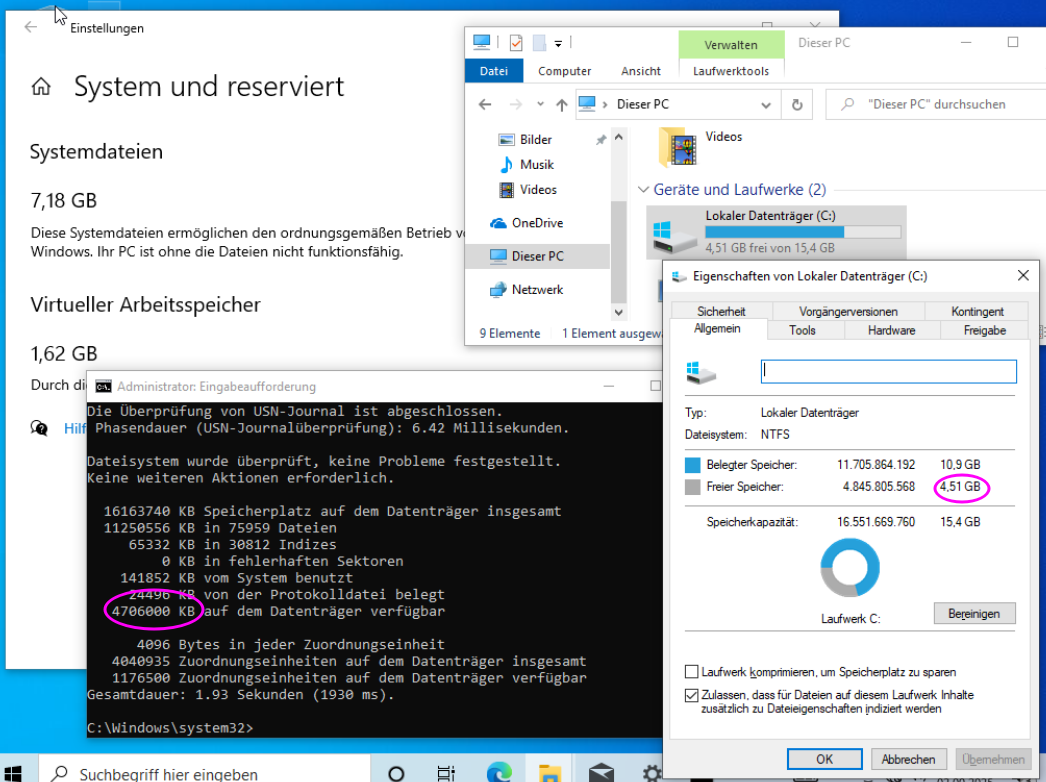
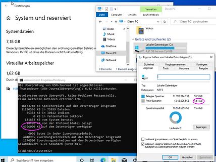
links oben zwischen "Systemdateien" und "Virtueller Speicher" angezeigt worden). Explorer meldet 4,51 GB frei. Chkdsk meldet 4706000 kB verfügbar. Wenn ich den Wert von chkdsk zweimal durch 1024 teile. komme ich auf 4,49 GB. Das wirkt einigermaßen stimmig. Wenn ich nach meiner neuen Erkenntnis
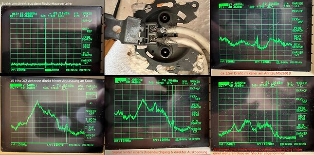
Spektrum direkt aus dem Radio-Hausverteiler
MKR:15.000MHz -05.51dBm
RL:-40.0dBm 5dB AT0dB S17
MKR=CF
PEAK SEARCH
NEXT PEAK
MIN SEARCH
MARKER (1)
CHF:15MHz SPF:10MHz RB100kHz VB100kHz
ca 1,5m Draht im Keller am Anritsu MS601B
15 MHz 1/2 Antenne direkt hinter Anpassung
Daten im Code sehr bequem, einfach den SP ins DPTR laden. Und am Ende nach DPTR springen. Der Keil C51 benutzt das z.B. bei switch/case.
mußte, um einen BASIC-Interpreter in 4 KiB zu bekommen: https://images.gatesnotes.com/12514eb8-7b51-008e-41a9-512542cf683b/34d561c8-cf5c-4e69-af47-3782ea11482e/Original-Microsoft-Source-Code.pdf
maximum peak current is Rated voltage/Maximum switching voltage V AC 250/400 See relays 120 A - 5 ms on normally Rated load AC1 VA 4,000 40.31 open contact. Rated load AC15 (230 V AC) VA 750 40.51 Single phase motor rating (230 V AC) kW 0.55 40.52 Breaking capacity DC1: 30/110/220 V A 16/0.3/0.12 40.61
und lässt die anfängliche Rot-Phase mal kürzer und mal länger sein: [c] : _delay_ms(2000); for (int i=rand()%500; i>0; i--) _delay_ms(10); // rot 0..5s länger PORTB = 0b1010; // Gelb : [/c] Für ein Spielzeug ist das auch ohne wirklich
if the MSB is 0 or 1. If the MSB = 0, simply multiply the decimal Normal Mode Fast Mode SPS Time (ms) SPS Time (ms) code by 0.03125°C to obtain the result. If the MSB = 1, subtract 1 from the result and complement all bits, multiply the result 20 49.99 40 25.00 by -0.03125°C. 45 22.25 90 11.12 90 11.26 180 5.63 175 5.78 350 2.89 330 3.04 660 1.52 600 1.68 1200 0.84 1000 1.01 2000 0.51 22 sps.honeywell.com/ast Advanced Sensing Technologies 23 TruStability™ Board Mount Pressure Sensors TruStability™ Board Mount Pressure Sensors RSCSeries RSCSeries Table 3-3. Data Interpretation Table
oft stören dann auch MOQs. Da ist nichts Böses daran. Und male den Teufel nicht an die Wand - was 51st State "Anschluß" betrifft reagieren wir neuerdings sehr empfindlich auf solche Anspielungen:-) Der SW-Unterschied ist eine Hersteller Entscheidung. Es hat mich schon sehr gewundert. Zur Zeit warte
neuester Sensor zur Verfügung steht. Nun, Abweichungen gibt es - Man denke nur an den ersten Intersema MS5344 Sensor. Bei dem war das I2C Protokol auch "verballhornend" umgesetzt und konnte nur als einzelner Busteilnehmer eingesetzt werden. Spätere Versionen wurden dann dem I2C Standard angeglichen. Wahrscheinlich
Reg0x0A : Temperature ADC data Register Reg0x30 : Measurement Command Register Sleep_time<7:4>: 0000:0ms; 0001:62.5ms; 0010:125ms ;... 1111: 1s, only active during sleep mode conversion. Sco: 1: Start of conversion, automatically come back to 0 after conversion ends (except sleep mode conversion). XGZP6857D_DataSheet_EN_V2.7
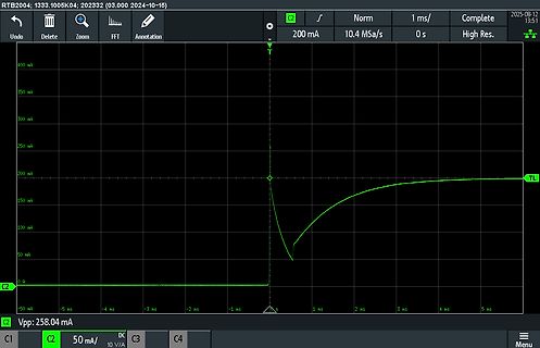
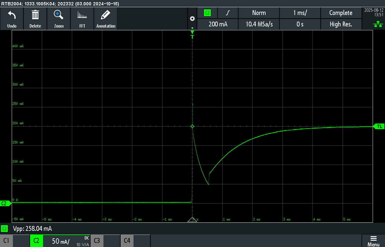
RTB2004: 1333.1005K04; 202332 (03.000 2024-10-16) 2025-08-12 13:51 C2 1 ms/ Norm 0 s Complete 200 mA High Res. 400 mA 350 mA 300 mA 250 mA 200 mA 150 mA 100 mA 50 mA 0 A -50 mA -5 ms -4 ms -3 ms -2 ms -1 ms 1 ms 2 ms 3 ms 4 ms 5 ms TL Vpp: 258.04 mA C1 C2 50 mA/ DC
connected potential-free or <5V: inactive = logical 0 (Terminals 41, 42, 43, 45, 48, 49, 58, 56, 54, 52, 51) >7V: active = logical 1 Min. signal length for input control commands: > 100ms Galvanic separation via optoelectronic coupler on printed circuit board Serial Interface 1 For electronic limit switches
adapter adjustment only). 10 On the oscilloscope, press CHAN and set the sensitivity to 1 mV/div. 51 Calibration Tests and Adjustment Attenuator Adapter Adjustment 11 Connecttheadapter/probecombinationtothetestboardinthepositionshown in the figure below (signal to both inputs). Figure 2-25 Signal to
Spezifikationen haben. 1. https://www.oyostepper.com/goods-43-Nema-17-Stepper-Motor-Bipolar-18-deg-36Ncm-51ozin-168A-28V-42x42x39mm-4-Wires.html 2. https://www.oyostepper.com/goods-34-Nema-17-Stepper-Motor-Bipolar-18-deg-26Ncm-368ozin-04A-12V-42x42x34mm-4-Wires.html Beide sind Nema-17-Motoren, und ich sehe
und damit seine Nennkraft erreicht hat. Der "Hochspannungsmotor" braucht da bis zu sienen 0,4A mit 5ms locker die 10-fache Zeit. Also gilt: der Stromanstieg bis zum Nennstrom(!) an *gegebener Versorgungsspannung* ist beim "Hochspannungsmotor" 10 mal langsamer. Und deshalb kann der bei *gleicher Versorgungsspanung
1P8withInternalLowDropoutRegulator(LDO)Bypassed V SUPPLY=0V 1.62 1.8 1.98 V SupplyResetThreshold(V ) 1.2 V RESET HoldTime 1 ms analog.com Rev. 0 | 5 of 103 Data Sheet ADXL380 SPECIFICATIONS Table1.Specifications(Continued) TestConditions/ Parameter Comments Min Typ Max Unit RiseTime 0Vto90%ofV S 4 ms 11 SupplyCurrent LDOenabled

 Bild
 Bild
 Bild
 Bild
 Bild
 Bild
 Bild
 Bild
 Bild