Read PROM low byte data to W and TABR (W = TABR = 86h) MOVXW TABR ; Read TABR to W (W = 86h) MOVLW 02h ; TABR write 02h = instruction TABRH MOVWX TABR ; read PROM high byte data to W and TABR (W = TABR = 19h) MOVXW TABR ; read TABR to W (W = 19h) … ORG X00h TABLE1: ADDWX PCL, 1 ; Add the W with PCL,
is 1, the result is stored back in register 'f'. Cycle 1 Example SUBWX REG1, 1 B : REG1 =0x03, W =0x02, C =?, Z =? A : REG1 =0x01, W =0x02, C =1, Z =0 SUBWX REG1, 1 B : REG1 =0x02, W =0x02, C =?, Z =? A : REG1 =0x00, W =0x02, C =1, Z =1 SUBWX REG1, 1 B : REG1 =0x01, W =0x02, C =?, Z =? A : REG1 =0xFF,
August 2016 4 of 31 NXP Semiconductors PCA9532 16-bit I C-bus LED dimmer 6. Functional description Refer to Figure 1 “Block diagram of PCA9532”. 6.1 Device address Following a START condition, the bus master must output the address of the slave it is accessing. The address of the PCA9532 is shown in Figure
RINGBANDKERNE TOROIDAL TAPE CORES a i d e k▯ h UNSER WEG / OUR WAY WAASNER // UNSER WEG / OUR WAY _____ 02 // 03 UNSER WEG OUR WAY Unser Weg beginnt im Jahre 1946. Die Brüder Kurt und Bruno Waasner gründen Our way begins in 1946. Brothers Kurt and Bruno Waasner establish the die Elektromechanischen Werkstätten
Da bist du preislich über dem Bereich wo der Chinese dir ein LCR-Messgerät Zoyi ZT-DQ01 oder ZT-DQ02 mit wesentlich mehr Funktionen verkauft und liefert. https://de.aliexpress.com/item/1005008703519215.html Vorletzte Position "Farbe: ZT-DQ01 with clip" auswählen: 55 Euro Versand dazu aktuell noch mal 5 Euro Rabatt möglich = 50 Euro. Wenn du noch ein paar Euro drauf legst kannst du das ZT-DQ02 kaufen (Auswahl "ZT-DQ02 with clip"). Das kann zusätzlich noch den Innenwiderstand von Batterien messen. 69 Euro dazu aktuell 12 Euro Rabatt = 57 Euro. Aktuelles Problem: Der 11.11. und weitere große
output latch function C: Without CO pin output latch function (CTL pin is pulled up internally) *1. Refer to the tape drawing. *2. Refer to “3. Product Name List”. (2) 8-Pin TSSOP S-8264 x xx - T8T1 x Environmental code U: Lead-free (Sn 100%), halogen-free G: Lead-free (for details, please contact our
of the dotted resistances in figure 7.2 is removed as the last step. With Z = 50Ω this yields: 0.02 0.02 −0.02 −1 Y trans= Ztrans− 10mS·E = 0.02 0.02 −0.02 (7.8) −0.02 −0.02 0.02 The upper left and upper right corner contains [Y ] and [Y ]: [Y ] = 0.02 0.02 [Y ] = −0.02 (7.9) 0.02 0.02 −0.02
Spannungsteiler und den ADC (PB3) aktiviert, einen dummy-ADC-Zyklus startet und die eff. Spannungen an ADC_REF (PB3) und PTC_IN (PB4) einliest. Die Ergebnisse ADC_max und ADC_werden anschliessend in der Funktion 'berechne_celsius()' per Tabelle ausgewertet und umgerechnet. Die Routine 'sende_werte()' erledigt
0x00 0x01 +14 +10 0x01 +13 +22 0x04 0x07 High power +20 0x03 0x05 +22 (RFO_HP) 0x00 0x01 +17 0x03 0x02 +14 0x02 +14 AN5457 - Rev 3 page 19/75 AN5457 Power amplifier network Caution: To avoid exceeding the maximum ratings that may cause irreversible damage to the device, some restrictions must be followed
,"NOTE HOW THE # AND ! WORK",# NOTE HOW THE # AND ! WORK *TYPE A, !,B,# 1.000000 2.000000 *TYPE %5.02,AB,"hi",12345.5456 -6.00hi2345.55: The examples are in immediate mode where their results were immediately visible. The only modification for program storage would be the addition of line numbers. It
Measurement freq. : 120Hz Tolerance ± 20% Measurement volt. : 0.5Vrms+1.5V DC DissipationFactor(tanδ) Refer to Standard Ratings Measurement freq. : 120Hz Measurement volt. : 0.5Vrms+1.5V DC Leakage Current (LC) Refer to Standard Ratings Rated voltage after 5 minuets Equivalent Series Refer to Standard Ratings
Elektromagnetischer-Stahlt%C3%BCrsauger-Wandhalterung-Brandschutzt%C3%BCr-Holzeisent%C3%BCren/dp/B09QD2PZMK/ref=asc_df_B09QD2PZMK Aber Erziehung geht einfacher. Auch wenn ich weiß wie man Kindern das ganz sanft beibringen kann, will ich keine Erziehungsratschläge geben.
de.wikipedia.org/wiki/Zwangsst%C3%B6rung Mit freundlichem Gruß: Bernd Wiebus alias dl1eic http://www.l02.de
MCU AD functionality, Our module default configuration 2 AD port, 20 key resistance distribution. Refer diagram https://wiki.dfrobot.com/DFPlayer_Mini_SKU_DFR0299 5/15 2020/6/3 DFPlayer_Mini_SKU_DFR0299-DFRobot 3. I/O Mode Here comes the most simple way to use this module. Refer diagram note: short time
/T32A02INB0/ TSPI4RXD/T32A04OUTC/VO0 20 T32A02INA1/EA09/INT05a/PB1 PLD_MODE DSP_PON O O PLD Mode Signal PD3/ED03/EAD03/T32A04OUTB/ T32A02INC0/T32A02INA0/T32A02INB1/ 51 TSPI4TXD/YO0 EEP_MOSI AC O O EEPROM Transmit
0.50 C t 0.20 ( 0.10 e 0.05 n 0.1 R1 R2 R3 R4 Ri (°C/W) τi (sec) o R1 R2 R3 R4 1.55246 0.005303 s 0.02 τJJ Cτ R 0.01 τ1 τ τ τ 0.00682 8.250407 l 1 22 3τ3 4τ4 0.00172 6.932919 a 0.01 r CCi τi/Ri 0.43999 0.000317 h SINGLE PULSE Notes: T ( THERMAL RESPONSE ) 1. Duty Factor D = t1/t2 2. Peak Tj = P dm x Zthjc
Furthermore, the MS5800 automatically determines the phase and amplitude of the reference signal V REF required to null each channel on a known calibration standard, and can perform digital filtering without the need for additional electronics. The input resistance of the data acquisition system MS5800
the original request previously sent on that TCP connection: If the Transaction Identifier doesn't refer to any MODBUS pending transaction, the response must be discarded. If the Transaction Identifier refers to a MODBUS pending transaction, the response must be parsed in order to send a MODBUS Confirmation
MODBUS over serial line specification and implementation guide V1.02 Modbus.org MODBUS over Serial Line Specification and Implementation Guide V1.02 Modbus.org http://www.modbus.org/ 1/44 Dec 20, 2006 MODBUS over serial line specification and implementation guide V1.02
Ein originaler LM317 verwendet eine interne Spannungsreferenz, die > zwischen 0°C und 150°C etwa 0,02V verliert. Der Spannungsteiler am Blödsinn. Da steht was ganz anderes drin ...
arretiert. Ich glaube die gibt es auch in kleineren Mengen. https://www.amazon.de/dp/B07DJYW6P3?ref=ppx_yo2ov_dt_b_fed_asin_title
So, der Lampensockel ist raus aus der Fassung. Auf dem steht geschrieben: 230V 40W PDH 02/25 230V 40W 300°C .● Des|ntegrator ●. schrieb im Beitrag #7940802: > Wie oft wird der Herd genutzt? Alle 1-2 Wochen mal. Fritz G. schrieb im Beitrag #7940843: > Ist da vielleicht gerade ein
PCB ASSY and "EXPLODED VIEW" and "EXPLODED VIEW" and "EXPLODED VIEW" CD PCB CD MECHAASSY SIDE PANEL (Ref. No. of EXPLODED VIEW:C30) (Ref. No. of EXPLODED VIEW:P13) (Ref. No. of EXPLODED VIEW:C23) SHIELD CASE See "DISASSEMBLY" 7. SHIELD CASE and "EXPLODED VIEW" SHIELD CASE (Ref. No. of EXPLODED VIEW:M7)
..........................+260°C for 10 seconds Soldering Temperature (surface mount)…..……………………….Refer to the JPC/JEDEC J-STD-020 Specification. Stresses beyond those listed under “Absolute Maximum Ratings” may cause permanent damage to the device. These are stress ratings only, and functional operation
EMMA Technical Specifications Technical Specification EMMA-A02 General Data Dimension(W × H × D) 108 mm × 100 mm × 65 mm Mounting type DIN35 Rail Height requirement of cabinet ≥ 47.5 mm Weight 0.5 kg Power Supply AC Voltage 1P2W: 100 ~ 240V, 50 / 60Hz 3P3W: 346
deflnes the color of the device, standard red. I I WWW. 2 HPARCHIVE.COM 1 0 09 08 0 7 0 6 0 5 00 4 0.3 02 0 1 DC 0 t p PULSE DURATION -PS TA -AMBIENT TEMPERATURE - "C I P E A K - ~ P ( T A ) =* t(FIGURE1)I Figure 1. MaximumAllowed Peak Current vs. PulseDuration. Derate derived Figure 2. Temperature Derating
current,VPD −V S OUTPUT CHARACTERISTICS SaturatedOutputVoltageSwing R LOAD 1 kΩ High +VS−0.04 +V S0.02 V Low −VS+0.04 −VS+0.03 V Linear Output Current3 Sourcing,G=+1,V =IN ,R S LOAD=varied 50 mA Sinking, G = +1,VIN −V S RLOAD= varied 60 mA Short-Circuit Current Sourcing, G = +1,VIN= +V S RLOAD 0 Ω to
Einzel- bzw. Doppelschläge passend abspielen, evtl. so ein Modul: https://www.amazon.de/dp/B07Y9TH6M7/ref=sr_1_1_sspa Über Sensoren müsstest du das Schlagwerk mit der Uhr verbinden, d.h. Sensoren für die halbe und die volle Stunde an der Minutenachse, sowie z.B. ein Sensor mit Kodierscheibe für die Synchronisation
John_Harrison_(Uhrmacher) Über den gab es mal eine TV-Sendung, ich denke die hier: ZDF: Mission X: 02. Entscheidung Längengrad (D 2002)
19 PIO 07 16.75 1.00 17.76 19.68 PIO 00 7 18 PIO 10 0.524 RXD 8 17 PIO 03 26.92 1.00 CTS 9 16 PIO 02 RTS 10 15 PIO 11 1.80 USB DP 11 14 AIO 0 USB DM 12 13 AIO 1 8.51 16.79 mm 8mm Minimum No Ground Zone Pio Assignments Only for this KC‐21 v6 module, our previous kcSerial v2.4 firmware edition provided
changed (see table under Power Pcb desciption) so that the power supply can initialise. 9 Calibration Refer to the General section for dismantling instructions and safety precautions. Normal calibration is done without opening the instrument. Allow 10 minute warm-up before commencing calibration. Refer to
Table 1-1) CS-ADC This section gives a high-level overview of the compensation mathematics. Please refer to Section 2.0 for details on exact DRDY PGA 24-bit ADC DIN numeric formats and EEPROM addresses. It is assumed that all values have been correctly converted to a floating-point decimal DOUT SCLK format
Pressure Type(Positive&Vacuum) ■ For Non-corrosive Gas or Air ■ Calibrated Digital Signal(I2C Interfa(Refer to XGZP6857A for Analog signal) ■ Temp. Compensated: 0℃~+60℃(32℉~+140℉) ■ Temperature Measurable ■ Affordable Cost, Easy-to-use APPLICATIONS ■ Medical&Healthcare ■ Industrial&Automation ■ Domestic
covers block-level theory for the 1141A/1142A differential probe system. Refer to the block diagram below. The differential probe system consists of two units, the 1141A Differential Probe with its accessories and the 1142A Probe Control and Power Module. For purposes of the
HCPL0531, HCPL0534 SCHEMATICS N/C 1 8 V CC + 1 8 V CC V F1 + 2 7 VB* _ 2 7 V 01 V F _ _ 3 6 3 6 V O V 02 V F2 N/C 4 5 GND +4 5 GND Figure 1. Single−channel Circuit Schematics Figure 2. Dual−channel Circuit Schematics (HCPL0500, HCPL0501 (HCPL0531, HCPL0534) *Base Not Connected for HCPL0453) ABSOLUTE MAXIMUM
9ad1-2bc21b36b985-43&pdp_ext_f={"order"%3A"165"%2C"eval"%3A"1"}&pdp_npi=4%40dis!EUR!2.49!0.99!!!20.02!7.97!%40211b80d117539984017997360e3437!12000043535149941!sea!DE!0!ABX&curPageLogUid=m7myZwhffWz0&utparam-url=scene%3Asearch|query_from%3A Könnten die passen ? Sehe gerade sind zu klein, aber ich
HOLD UP TIME (Typ.) 30ms/347VAC, 480VAC 180 ~ 528VAC 254VDC ~ 747VDC VOLTAGE RANGE Note.5 (Please refer to "STATIC CHARACTERISTIC" section) FREQUENCY RANGE 47 ~ 63Hz POWER FACTOR (Typ.) PF≧0.98/230VAC, PF≧0.98/277VAC, PF≧0.97/347VAC, PF≧0.93/480VAC @full load (Please refer to "POWER FACTOR (PF) CHARACTERISTIC
CONDITIONS MIN TYP MAX UNIT LM1117-ADJ 1.238 1.25 1.262 OUT = 10 mA, VIN – VOUT = 2 V, J = 25°C V REF Reference voltage LM1117-ADJ TJ= 25°C 1.25 V 10 mA ≤ I ≤ 800 mA, 1.4 V ≤ OUT over the junction temperature range 1.225 1.27 VIN– VOUT ≤ 10 V 0°C to 125°C LM1117-1.8 1.782 1.8 1.818 OUT = 10 mA, VIN

 Bild
Bild
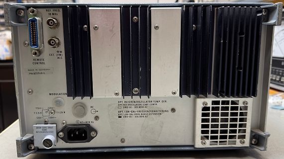
 Bild
Bild

 Bild
Bild