Device Coil Voltage Suppressor Catalog Number Type(4) Bulletin 100/104K 700K 24…48V AC 100-KFSC50 RC 110…280V AC 100-KFSC280 380…480V AC 100-KFSC480 12…55 V AC, 12…77V DC 100-KFSV55 MOV 56…136 VAC, 78…180V DC 100-KFSV136 137…277VAC, 181…250 V DC 100-KFSV277 12…250V DC 100-KFSD250 Diode Bulletin 100C, (C09 - C97) 24…48V AC 100-FSC48(1) RC 110…280VAC 100-FSC280(1) 380…480VAC 100-FSC480(1) 12…55VAC, 12…77V DC 100-FSV55(1) MOV 56…136VAC, 78…180V DC 100-FSV136(1) 137…277VAC, 181…250V DC 100-FSV277(1) 278…575VAC 100-FSV575(1) 12…250V DC 100-FSD250
müsste der aber bei roundabout 6 Megaohm sein (Leistungsaufnahme Glimmlampe max. 1,5mA; hFe (gemessen: 110), Spannung Glimmlampe 200V) Kann das überhaupt stimmen? Weil ich so einen Widerstand grade nicht parat hatte, habe ich erstmal einen 750 kOhm Widerstand vor die Basis gemacht, was an der Situation
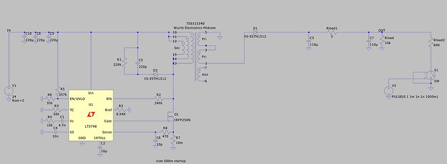
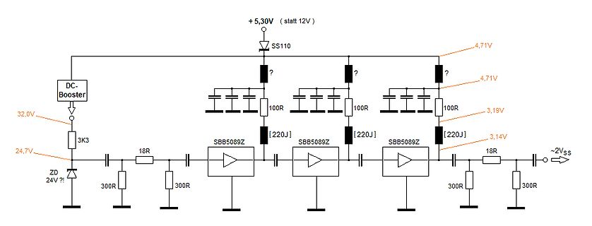
und als Ansteuerung ein К155ИД1 verwendet. Ich weiß aber genau, dass ich hier noch was mit diesen ss2xx schalttransistoren in der Schublade hab, wo das, wie oben angerissen, gemacht wurde. (Schaltplanauszug/ Screenshot anbei)
provide the same functions in batch-file operation. The LIFUTIL can also work with LIF disks in CS-80 / SS-80 disk drives connected to the PC through HP 82990 or 82335 HP-IB cards; such drives are designated by: SSBB[,UU[,V]] -- where: SS HP-IB card select code. BB Drive HP-IB address. UU Drive unit number
.. +lO % 48...62Hz ca. 40 w T 0.315 A Stromversorgung ,Netzspannung) Netzspannungswahlschalter Bei 110 V muSder Netzspannungswahlschalter auf 120 V gestellt werden! BE412B versorgungs-Spannung Spannungsbereich Frequenzbereich Leistungsaufnahme Netzsicherung IlOV- 85V--132v- M2A 17OV--264V- 4S...62Hz
CRT Center) 1000 TV lines typ 1000 TV lines typ (CRT Center) ChaVerticalrea: Horizontal 4.33±0.2" (110±5mm) 5.91±0.2" (150±5mm) 5.91±0.2" (150 ±5mm) 6.30±0.2" (160±5mm) 8.46±0.2" (215±5mm) 8.46±0.2" (215 ±5mm) Blanking Time: Vertical 1000µs min. 1000µs min. 840µs min. Horizontal 10µs min. 10µs min. 1Oµs
https://www.youtube.com/watch?v=Vfki55ZcfSs#t=20m45s Hier will einer die Einsparungen ausrechnen. Kann er rechnen? Erstmal vertut er sich mit Video und Rechnung. Zufall? Er redet von 181.000 Euro Einsparung bei 170.000km/Jahr Diesel
als 20 Minuten. Ergo ist das Auto nicht das Problem. Ja ich weiß, mit Wohnwagen 1000km am Stück bei 110 geht halt dann nicht. Aber bis auf ein paar Vollidioten, die es noch nicht besser wissen, ist das für fast keinen relevant.
de.aliexpress.com/item/32966157667.html 2,35€/10 M5x50 ISO7380 Bild fehlt zeigt die Montage von zwei GH-4001-SS Toggle Clamp VA die das pendeln der Kabine verhindern. (siehe externes Forum) https://de.aliexpress.com/item/1005005097317249.html 2,17€/1 Solarmodule ------------------------------------------
TOFF= L I/(V LED + VD+ I avg(RS+ rL) ) Where L is the coil inductance rL is the coil resistance R Ss the current sense resistance Iavgis the required LED current I is the coil peak-peak ripple current (internally set to 0.3avgI V IN the supply voltage V LEDis the total LED forward voltage R SW is the
unless otherwise specified) Item Symbol Absolute maximum rating Unit VIN pin voltage A, C, E types V V SS 0.3 to SS 12.0 V B, D, F types IN V SS 0.3 to SS 18.0 V VOUT pin voltage A, C, E types V V SS 0.3 to SS 12.0 V B, D, F types OUT V SS 0.3 to SS 18.0 V ______ A, C, E types V OFF___ V SS
IG G 1 ¼" IG Heizwasserrücklauf G 1 ¼" IG G 1 ¼" IG G 1 ¼" IG G 1 ¼" IG G 1 ¼" IG Flansch TK150/DN110 DN 110 (TK 150) 8 Loch DN 110 (TK 150) 8 Loch DN 110 (TK 150) 8 Loch DN 110 (TK 150) 8 Loch Anoden Durchmesser 33 mm 33 mm 33 mm 33 mm 33 mm Anodenlänge 685 mm 750 mm 850 mm 1100 mm 590 mm Anoden G
Auswerte-Elektronik MT 101 MT 60 MT 2500 MT 1200 8 12 mm 25 mm/ 60 mm 100 mm Seite 30 mm 18 CT 2501 » 11 µA SS CT 6001 » 11 µA SS CT 2502 » 11 µA SS CT 6002 » 11 µA SS 20 MT 1201 » 11 µA SS MT 2501 » 11 µA SS MT 1271 « TTL MT 2571 « TTL MT 1281 » 1 V MT 2581 » 1 V SS SS MT 1287 » 1 V SS MT 2587 » 1 V SS 22 MT 60M » 11 µA SS MT 101M » 11 µA SS MT 60K » 11 µA SS MT 101K » 11 µA SS 24 ST 1208 » 11 µA SS ST 3008 » 11 µA SS ST 1278 « TTL ST 3078 « TTL ST 1288 » 1 V SS ST 3088 » 1 V SS ST 1207 » 11 µA SS ST 3007 » 11 µA SS ST
VDD VCC + C 4.7F 12 IRS2110 1 R1 Q3 25V Q5 INPUT LIN LO 100 G + 1µF Q4 100V 16µF VSS 0.1 F 0.1µF IRFD110 E 500V 13 Q2 E IRFD110 +15V RTN +100 V RTN Figure 11: Test Circuit www.irf.com AN-978 RevD 14 The typical switching performance while driving an inductive load current of 60 A is shown in Figures 12A
NPN-Transistoren? Und weiß zufällig jemand, ob man statt der Verpolungsschutzdiode in der positive Zuleitung (SS110) einen P-Ch-MOSFET als Verpolungsschutz einsetzen kann und wenn ja, wie man ihn anschließen muss?
current of 10 mA. If the battery backup feature is not being used, the VBAT pin should be connected to SS. 3.3 Chip Select Input (CS) A low level on this pin selects the device, whereas a high level deselects the device. A nonvolatile memory programming cycle that is already initiated or is in progress will
if it can be lax in smartwatch to internet-of-things gadgets to critical infrastructure, practice [110, 134, 152]. As a result, users often give little-to-no con- such as smart meters. The requirements are simply (1) less expen- siderationbeforedownloadingthird-partyapplications[65,74,107], sive flash
4.475 Mean O Mean _0.880 P V0.995 B V V0.875 O 4.470 0.990 0.870 4.465 0.98-50-30 -10 10 30 50 70 90 110 130 0.86-50-30 -10 10 30 50 70 90 110 130 4.46-50-30 -10 10 30 50 70 90 110 130 V_DIS vs. V_BURL vs. V_BURH vs. Temperature Temperature Temperature 6.150 0.682 0.782 0.781 6.100 0.681 0.780 0.680 )
900ss schrieb im Beitrag #7668293: > Eigentlich ist das hier OT. Danke. Das ist meine Rede. Das Thema kann gern näher erörtert werden. Aber hier in dem Thread gibt es wichtigere Dinge als diesen Nebenkriegsschauplatz
14718 0 .debug_abbrev 13926 0 .debug_line 110 0 .debug_str 6471 0 .debug_line_str 123 0 Total 37652 [/pre] MIT Flag -mrodata-in-ram kompiliert avr-size.exe
so by the user. All other pins are inputs. When SS is driven high, all pins are inputs, and the SPI is passive, which means that it will not receive incoming data. Note that the SPI logic will be reset once the SS pin is driven high. The SS pin is useful
defined for the SPI bus by the value of the MOSI MOSI clock polarity and the clock phase bits. The clock SS 1 SSSO SS 2 polarity determines the level of the clock idle state and SS 3 SCLK SLAVE 2 the clock phase determines which clock edge places MISO MASTER SS new data on the bus. Any hardware device capable
bits (TCA.PER=MAX). The following equation calculates the exact resolution for single-slope PWPWM_SS ): log PER+1 PWM_SS = log 2 The single-slope PWM frequency (fPWM_SS ) depends on the period setting (TCA_PER), the system's peripheral clock frequencyCLK_PER, the TCA prescaler (CLKSEL in TCA.CTRLA).
------------- Connection Index : 0x02 (2) Length : 0x10 (16 bytes) SupportedUsbProtocols : 0x03 Usb110 : 1 (yes, port supports USB 1.1) Usb200 : 1 (yes, port supports USB 2.0) Usb300 : 0 (no, port not supports USB 3.0) -> but Companion Port 2-6 does ReservedMBZ : 0x00 Flags : 0x00 DevIsOpAtSsOrHigher : 0 (Device is not operating at SuperSpeed or higher) DevIsSsCapOrHigher : 0 (Device is not SuperSpeed capable or higher) DevIsOpAtSsPlusOrHigher : 0 (Device is not operating at SuperSpeedPlus or higher) DevIsSsPlusCapOrHigher : 0 (Device is not SuperSpeedPlus
auf korrekte werden und macht bei den resultierenden Konfiguration des Taktgenerators achten. 6 V SS ordentlich Lärm. Das verwendete Nicht jede Programmer-Software liest die Exemplar KPEG827 von Kingstate [3] Konfiguration richtig ein. Die korrekten eignet sich für den Frequenzbereich von Werte sind
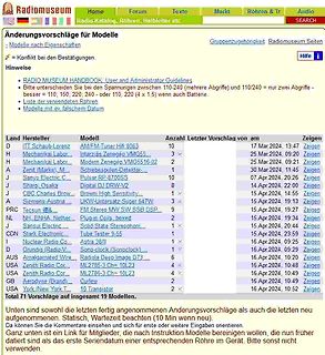
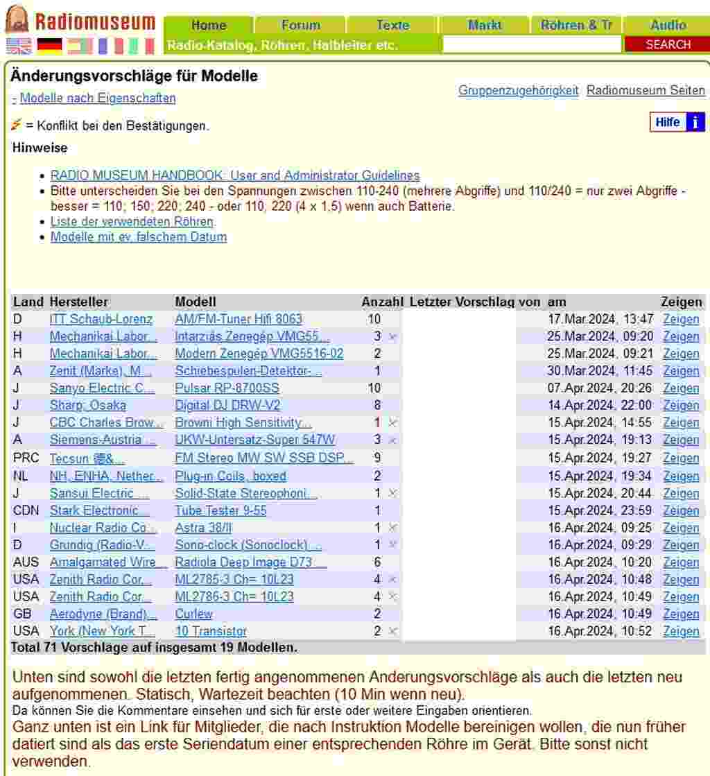
Hinweise
RADIO MUSEUM HANDBOOK User and Administrator Guidelines
Bitte unterscheiden Sie zwischen 110-240 (mehrere Abgriffe) und 110/240 = nur zwei Abgriffe - besser = 110; 150; 220; 240 oder 110; 220 (4 x 1.5) wenn auch Batterie.
Liste der verwendeten Röhren
Modelle mit ev falschem Datum
Land Hersteller
47 Appendix B: BIOS Operation Kontron 21.3 Main Menu Feature Option Description System Time HH:MM:SS Set system time. Press <Enter> to move to MM or SS. System Date MM/DD/YYYY Set system date. Press <Enter> to move to DD or YYYY. Legacy Diskette A 360 kB, 5 … Select type of installed floppy disk drive
Kommunikationsmodi. In der folgenden Tabelle sind die Verbindungsmethoden der SS-Pins anderer Geräte am SPI-Bus unter verschiedenen SPI- Kommunikationsmodi von SC93F833X aufgeführt: SC93F833X SPI Andere Geräte am SPI-Bus SS (Slave-Geräteauswahl-Pin) des Mode-Slaves , ein Master und ein Slave auf Low gezogen SC93F833X führt zu mehreren I/Os, die jeweils mit dem SS-Pin des Slaves Hauptmodus Slave-Modus Ein Herr, viele Sklaven verbunden sind. Vor der Datenübertragung muss der SS-Pin des Slave- Geräts auf Low gesetzt werden, der Master Slave-Modus Hauptmodus und
B 1 0 2 ± 7 7 2 2 e x 1S B = 6 6 5. v DDVB 1 C 2 2 2 t 8 SS V 0 0 I c 2 TAB V ( ± P 1 N1 C 0 8 S A N2 CC 0 0 r P2 C P w 1 CN B 4 3 0 l 6 l 03 ) 8 4.75 0 r 0 0 78 4 6 1 P ± ± . 2 11 3 T X e . ( ( (2.1) 10.864 (A/A) 12.0± 0.3 1 Q X n 0 S r: 8 e (1.1) 12.864 (V/

 Bild
 Bild
 Bild
 Bild