
-
PDF
Master-thesis_Wenzel-Maier_final-version.pdf
2 · α(t). (46) The matrices A ,1B ,1C an1 D are 1mode-1" matrices with those elements are active when switch Q5 is closed (Q6 opened), while matrices A , 2 , 2 an2 D are \2ode-2" matrices with those elements are active when switch Q6 is closed (Q5 opened). In matrix B, C and D every term is active during
in „Platinfuchs IIa: Isolierter, bidirektionaler 45W DC/DC Wandler zum Laden/Entladen eines Liion-Akkus“ · Projekte & Code ·
-
PDF
OPALjrManual.pdf
the highlighted keyword. 2.5 THE VIEW MODULES MENU This menu is very useful during a design phase, when the user is compiling the source file for the first time. This menu contains selections that allow the user to view the different output files of the last executed procedure. Any of the following files
in „Suche Infos zu ICT Peel 18CV8P 35NS Software JDEC File erzeugen?“ · Mikrocontroller und Digitale Elektronik ·
-
PDF
AAA4000C337.pdf
*1 Without tabs. • Excellent low-temperature performance enhanced by *2 Please consult Panasonic when anticipating usage in operating temperatures of manganese-dioxide positive pole 70°Cor above. Applications Terminal types Please see the documents for the terminal and lead wire settings. Remote keyless
-
PDF
NOAH_2000_User_Manual-05-1.pdf
off. 2. Solar Panel Connection Indicator: The icon lights up to indicate solar panel connection. When the PV input power is below 25W, the icon flashes quickly; when it exceeds this value, the icon remains steadily lit. 3. Micro-inverter Operation Indicator: The icon lights up to indicate that the NOAH
in „Ecoflow Wechselrichter Eingänge in Reihe schalten?“ · Haus & Smart Home ·
-
PDF
bd7690fj-e.pdf
typ.) with the divided voltage of the output voltage, gmAMP controls the EO voltage by this gap. When EO pin voltage rises, ON width of the OUT pin becomes wide. When the EO voltage less than about 0.7V, the IC stops switching. Therefore it can stop switching operation when EO pin connects to the GND
in „Modulierung eines Hochsetzstellers mit PFC-Steuerung in PLECS – Hilfe bei Grundlagen der Steuerung g“ · Analoge Elektronik und Schaltungstechnik ·
-
PDF
2401120947_XINGLIGHT-XL-502UWC_C2895480.pdf
胶体。 When welding, welding must be conducted below 2mm of colloid bottom. When welding, try to avoid soaking LED colloid. After welding, avoid adding external force on the pin or shaking LED colloid. 推荐的焊接条件
in „TLC5941 Vorwiderstände und Spannungsversorgung“ · Mikrocontroller und Digitale Elektronik ·
-
PDF
AN332.pdf
allowed before setting the AFC rail indicator (AFCRL). The CTS bit (and optional interrupt) is set when it is safe to send the next command. This property may only be set or read when in powerup mode. The default is 20 kHz. Available in: All Default: 0x0014 (all others) Units: kHz Step: 1 Range: 0–255
in „Radioempfang: Mono statt Stereo erzwingen, UKW“ · HF, Funk und Felder ·
-
Datei
spi_struct.h
state.*/ uint32_t reserved24 : 5; /*reserved*/ uint32_t ck_idle_edge : 1; /*1: spi clk line is high when idle 0: spi clk line is low when idle. Can be configured in CONF state.*/ uint32_t cs_keep_active : 1; /*spi cs line keep low when the bit is set. Can be configured in CONF state.*/ uint32_t quad_din_pin_swap
in „C > Struct > Pointer - Adresszuweisung“ · Mikrocontroller und Digitale Elektronik ·
-
PDF
TLV431-DIO.pdf
sensitive and may be damaged by exposure to ESD events. Suitable ESD precautions should be taken when handling and transporting these devices.) Parameter Rating Unit Operating Junction Temperature -40 to +150 °C Storage Temperature -65 to +150 °C Operation above the absolute maximum rating may cause
in „Schaltung zur Ürberwachung der 9 Volt Batteriespannung“ · Analoge Elektronik und Schaltungstechnik ·
-
PDF
UC1698u_Revision__1.5.pdf
Ultra-Compact) 01 10 3-wire SPI w/ 9-bit taken (S9: conventional) CS0 1 Chip Select. Chip is selected when CS1=”H” and CS0 = “L”. When the chip is not CS1 I 1 selected, D[15:0] will be high impedance. When RST=”L”, all control registers are re-initialized by their default states. Since UC1698u has built-in
in „Defekte Heizungsregelung RC310 Display leuchtet“ · Haus & Smart Home ·
-
PDF
efm8ub2-datasheet-1666225.pdf
achieved by enabling/disabling individual peripherals as needed. Each analog peripheral can be disabled when not in use and placed in low power mode. Digital peripherals, such as timers and serial buses, have their clocks gated off and draw little power when they are not in use. Table 3.1. Power Modes Power
in „[V] nochmal 10St. SILABS 8051 USB-EFM8UB20F64G-B - QFP32 (10€)“ · Markt ·
-
PDF
AK-450_Series_Datasheet.pdf
230VAC Inrush Current (Typ.) 27A / 115VAC, 54A / 230VAC Leakage Current < 1.0mA / 240VAC Hiccup mode: when the rated output power is within 105 ~ 150% for more than 3secs. Constant current limit: > 150% rated power / short circuit Over Load Auto-recovery: If O/P drop to 40% of the rated output voltage, PSU
in „[V] 30V/15A + 5V/0,3A Schaltnetzteil Cotek AK-450-30“ · Markt ·
-
Thread
STM32H743 mit 32MByte externem SDRAM
for this Board and display and lvgl is running fine on this board due to a lot of RAM. edit: when I remove the I2C read, the it works, also your logo is displayed on the screen.
forum and I don't know what I do wrong, I can't read the memory at all. I use stm32 cube ide, and when I tried to read memory address 0xC0000000, it shows '????????', not a random hex, even when I tried to write some data, nothing changed. This is my first time dealing with sdram so I follow all the
Mikrocontroller und Digitale Elektronik ·Hans-Georg L. · ·96 Antworten
-
PDF
ZLDO1117.pdf
the board. Some experimentation will be necessary to determine the actual value. Ripple Rejection When using the ZLDO1117 adjustable device the adjust terminal can be bypassed to improve ripple rejection. When the adjust terminal is bypassed the required value of the output capacitor increases. The device will require an output capacitor of 22µF tantalum or 150µF aluminum electrolytic when the adjust pin is bypassed. Normally, capacitor values on the order of 100µF are used in the output of many regulators to ensure good load transient response with large load current changes. Output
in „Def. Mikrocontroller auf Geschirrspüler-Platine?“ · Haus & Smart Home ·
-
PDF
80C51.pdf
(OSC/12) 1 = External event counter (falling edge triggered). CP/RL2 T2CON.0 Capture/Reload flag. When set, captures will occur on negative transitions at T2EX if EXEN2 = 1. When cleared, auto-reloads will occur either with Timer 2 overflows or negative transitions at T2EX when EXEN2 = 1. When either
in „Prüfen von Chips“ · Mikrocontroller und Digitale Elektronik ·
-
PDF
FSUSB30-1010253.pdf
on the D+/D- 2 pins which allows the device to withstand an overvoltage 0 Applications condition when powered off. This device is also designed ( ? Cell phone, PDA, Digital Camera, and Notebook LCD to minimize current consumption even when the control 8 voltage applied to the S pin, is lower than the
in „Problem mit FSUSB30 als USB-Schalter“ · Mikrocontroller und Digitale Elektronik ·
-
PDF
MJW3281A.pdf
present. Some products may not follow the Generic Marking. Electronic versions are uncontrolled except when accessed directly from the Document Repository. DOCUMENT NUMBER: 98ASB15080C Printed versions are uncontrolled except when stamped “CONTROLLED COPY” in red. DESCRIPTION: TO−247 PAGE 1 OF 1 onsemi and
in „[V] 8x MJW3281A (NPN, 230 V, 15 A, 200 W, TO-247)“ · Markt ·
-
PDF
efm8ub2-datasheet-1666225.pdf
achieved by enabling/disabling individual peripherals as needed. Each analog peripheral can be disabled when not in use and placed in low power mode. Digital peripherals, such as timers and serial buses, have their clocks gated off and draw little power when they are not in use. Table 3.1. Power Modes Power
in „[V] 10St. SILABS 8051 USB-EFM8UB20F64G-B - QFP32 (10€)“ · Markt ·
-
PDF
TFT_320x240_05_7Z_LQ057Q3DC02_2x_262k_3_3V_FFC33x0_5mm_separat.pdf
to avoid rubbing with something hard or sharp. Please use ionized nitrogen to blow particle off. When polarizer is soiled, wipe out with cloth for lenses. ② When the metal parts of TFT-LCD module (shield case ) becomes dirty, wipe it out dry and soft cloth. If it cannot be removed easily, blow your
in „[V] 14,5cm (5,7")-TFT-Display 320 x 240 von Sharp“ · Markt ·
-
PDF
Infineon-TLE49X5L.pdf
TLE4905L, TLE4935L, TLE4945L, TLE4945-2L Functional Description Unipolar Type TLE4905 (Figure 3 and 4) When a positive magnetic field is applied in the indicated direction (Figure 3) and the turn-on magnetic inductionB OPisexceeded, theoutputof theHall-effect IC will conduct (Operate Point). When the current
in „Transistorzündung umrüsten auf Hallsensor“ · Analoge Elektronik und Schaltungstechnik ·
-
Datei
arctanFP.vhd
BEGIN IF rising_edge(clk) THEN IF nrst = '0' THEN stateatan <= 0; ce1 <= '0'; nd <= '0'; InpA <= (OTHERS => '0'); InpB <= (OTHERS => '0'); atanFPo <= (OTHERS => '0'); --TestOutp <= (OTHERS => '0'); --(OTHERS => '0'); ELSE CASE stateatan IS WHEN 0 => IF ceatan = '1' THEN InpA <= Xinp; InpB <= Yinp; ce1
-
Datei
arctanFP.vhd
3:= 0; BEGIN IF rising_edge(clk) THEN IF nrst = '0' THEN stateatan <= 0; ce1 <= '0'; --InpA <= (OTHERS => '0'); ---InpB <= (OTHERS => '0'); cntrclk := 0; --(OTHERS => '0'); ELSE CASE stateatan IS WHEN 0 => IF ceatan = '1' THEN stateatan <= 1; --InpA <= Xinp; --InpB <= Yinp; cntrclk := 1;-- time for
-
PDF
harman_kardon_avr145_sm.pdf
references Byte/Word Organization Select pin is used to to the Data Input/Output to include this pin when switch between the 8-bit and 16-bit Bus modes of the memory. When Byte/Word Organization Se- BYTE is High and references to the Address In- lect is Low, IL, the memory is in 8-bit mode, when puts to
in „Relais beim AVR 145 von harman/kardon durch SSR ersetzen“ · Analoge Elektronik und Schaltungstechnik ·
-
 Bild
Programmcode in einer Entwicklungsumgebung
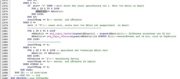
1870 END IF; 1871 WHEN 2 =>-- 1872 IF strt='1' THEN --strt dient der start speicherung von 1. Wert von Axinc in Axalt 1873 FOR i IN 0 TO 5 LOOP 1874 Axalt(i)<= Axinc(i); 1875 END LOOP; 1876 END IF; 1877 statITPimp <= 3;--
in „Post-Map simulation mit ModelSim“ · FPGA, VHDL & Co. · · Screenshots
-
Datei
AxConv.vhd
stateConv := 0; ceAinkr <= '0'; cemul <= '0'; cediv <= '0'; ceTO16 <= '0'; ELSE CASE stateConv IS WHEN 0 => IF ceConv = '1' THEN-- AFPint = Achsenwinkel in RAD FP ceAinkr <= '1'; --start AinkrFP := AFPint * C_AxRad[Inkr/Rad] stateConv := 1; ELSE stateConv := 0; END IF; WHEN 1 => --AinkrFP := AFPint *
-
Datei
ITPModul_tb.vhd
Koordinate Z signal tb_XT : std_logic_vector(31 downto 0) := (others => '1'); -- Koordinate X relativ (XE-XS) signal tb_YT : std_logic_vector(31 downto 0) := (others => '1'); -- Koordinate Y relativ (YE-YS) signal tb_ZT : std_logic_vector(31 downto 0) := (others =>
-
Datei
ITPModul.vhd
Stopp Exit ELSE -- kein stopp stateLinB <= S1;-- dann repeat END IF; -------------------------------- WHEN S4 => -- itp fertig stateLinB <= S5;-- normal exit -------------------------------------------- WHEN S5 => -- stop exit XLinA <= (OTHERS =>'0'); YLinA <= (OTHERS =>'0'); errX :=0; errY :=0; count :=
-
Datei
runangle.vhd
; ceSubw <= '1'; -- Start für sub/add FXa -/+ sAZAT3 usw stateangle <= 63; next_stateangle <= 11; WHEN 11 => -- ausführen sub/add FXa -/+ sAZAT3.. = FYw,FZw fertig ceSubw <= '0';-- reset stateangle <= 12; WHEN 12 =>-- für test stateangle <= 13; WHEN 13 => -- zwischen state notwendig *** IF grPI2 = '1
-
Datei
runangle.vhd
END IF; WHEN 1 => -- ausführen Xa,Ya,Zz=>FP und Pi/2-AZFP,Pi/2 +/- ATFP IF ctrclk > 0 THEN ctrclk := ctrclk -1; ceXYZFP <= '0';--reset CE stateangle <= 1; ELSE StartON := '1'; stateangle <= 2; END IF; WHEN 2 =>
-
Datei
func_c.vhd
statefktC <= 4; ELSE statefktC <= 3; END IF; WHEN 3 => Padd <= Pa; Qadd <= Qa; Pinp <= Pa; Qinp <= Qa; ce1 <= '1'; statefktC <= 1; WHEN 4 => --Run Add p0,q0 ce3 <= '0'; ce4 <= '1'; --start für div P/Q div Count := 1; statefktC <= 5; -- und warten auf Neustart WHEN 5 => IF count > 0 THEN count := count - 1; ce4 <= '0'; statefktC <= 5; ELSE statefktC <= 0; END IF; WHEN OTHERS => statefktC <= 0; END CASE; -- stateafkt END IF; -- nrst END IF; --clk END PROCESS; -
-
Datei
CosFP.vhd
RANGE 0 TO 7:= 0; BEGIN IF rising_edge(clk) THEN IF nrst = '0' THEN state := 0; cntrclk := 0; --(OTHERS => '0'); ELSE CASE state IS WHEN 0 => IF cecos = '1' THEN ce1 <= '1';-- start für 1-x, x`2, ComP0.5 state := 1; ELSE state := 0; END IF; WHEN 1 => --- Ausführen ain :=ainp^2 ce1 <= '0'; ce2 <= '1';-- start für fkt_c cntrclk := 11; state := 2; WHEN 2 => ---- mul2mX,2powX fertig IF cntrclk = 0 THEN state := 0;--warten auf nächste Start ELSE ce2 <= '0'; cntrclk := cntrclk -1; state := 2; END IF; WHEN OTHERS => state := 0; END CASE; END IF; -- if
-
Datei
atanFP.vhd
rising_edge(clk) THEN IF nrst = '0' THEN stateatan <= 0; cntrclk := 0; cecomp <= '0'; sign := "00"; --(OTHERS => '0'); ELSE CASE stateatan IS WHEN 0 => IF ceatan = '1' THEN IF (Yinp = X"00000000") AND (Xinp = X"00000000") THEN atanFP <= X"00000000"; stateatan <= 0;-- ungültige wert ELSE stateatan <= 1; END
-
Datei
arcCosFP.vhd
RANGE 0 TO 7:= 0; BEGIN IF rising_edge(clk) THEN IF nrst = '0' THEN state <= 0; cntrclk := 0; --(OTHERS => '0'); ELSE CASE state IS WHEN 0 => IF ceacos = '1' THEN ce1 <= '1';-- start für 1-x, x`2, ComP0.5 state <= 1; ELSE state <= 0; END IF; WHEN 1 => --- Ausführen 1-x,X`2,CompX ce1 <= '0'; ce2 <= '1
-
Datei
afkt.vhd
<= 2; WHEN 2 => Pplus <= Pmul; Qplus <= Qmul; ce2 <= '1'; stateafkt <= 3; When 3 => ce2 <= '0'; stateafkt <= 4; When 4 => Padd <= Pa; Qadd <= Qa; IF TabIdx = 0 THEN Pplus <= X"00000000"; Qplus <= X"00000000";
-
Datei
ITPModul.vhd
Stopp Exit ELSE -- kein stopp stateLinB <= S1;-- dann repeat END IF; -------------------------------- WHEN S4 => -- itp fertig stateLinB <= S5;-- normal exit -------------------------------------------- WHEN S5 => -- stop exit XLinA <= (OTHERS =>'0'); YLinA <= (OTHERS =>'0'); errX :=0; errY :=0; count :=
-
Datei
TopAS21.vhd
X"48" => StRcntr1 <= 5; WHEN X"50" => StRcntr1 <= 6; WHEN X"40" =>--keine ref anfahren REF01 <= '1'; StRcntr1 <= 9; WHEN OTHERS => StRcntr1 <= 0; END CASE;--RefBefehl WHEN 2 => --Ausführung RefBefehl:41= X Allein REFRUN2 <= '1'
-
Datei
ITPModul.vhd
Stopp Exit ELSE -- kein stopp stateLinB <= S1;-- dann repeat END IF; -------------------------------- WHEN S4 => -- itp fertig stateLinB <= S5;-- normal exit -------------------------------------------- WHEN S5 => -- stop exit XLinA <= (OTHERS =>'0'); YLinA <= (OTHERS =>'0'); errX :=0; errY :=0; count :=
-
Datei
ITPModul.vhd
Stopp Exit ELSE -- kein stopp stateLinB <= S1;-- dann repeat END IF; -------------------------------- WHEN S4 => -- itp fertig stateLinB <= S5;-- normal exit -------------------------------------------- WHEN S5 => -- stop exit XLinA <= (OTHERS =>'0'); YLinA <= (OTHERS =>'0'); errX :=0; errY :=0; count :=
-
PDF
UPA1721.pdf
diode connected between the gate and source of the transistor serves as a protector against ESD. When this device actually used, an additional protection circuit is externally required if a voltage exceeding the rated voltage may be applied to this device. The information in this document is subject
in „RC-Steller Kontronik Smile 30-6-12 Bestückung“ · Mikrocontroller und Digitale Elektronik ·
-
PDF
magnetic.pdf
the field quantities can be neglected, i.e. ∂/∂t = 0. This kind of fields is denoted as static field, when the magnetic, the electric and the current fields can be regarded independently, because there are no interactions between them. In time varying case when ∂/∂t = 0, the magnetic and electric fields are
-
Datei
ITPModul.vhd
Stopp Exit ELSE -- kein stopp stateLinB <= S1;-- dann repeat END IF; -------------------------------- WHEN S4 => -- itp fertig stateLinB <= S5;-- normal exit -------------------------------------------- WHEN S5 => -- stop exit XLinA <= (OTHERS =>'0'); YLinA <= (OTHERS =>'0'); errX :=0; errY :=0; count :=
-
PDF
CP2102-9.pdf
) RI 2 3 D In Ring Indicator control input (active low) SUSPEND 123 D Out This pin is driven high when the CP2102/9 enters the USB suspend state. SUSPEND 113 D Out This pin is driven low when the CP2102/9 enters the USB suspend state. NC 10, 13–22 These pins should be left unconnected or tied tDDV. Notes: 1. For CP2102, pin is no connect (NC). 2. For CP2109, pin isPP. PP can be left unconnected when not used for in-application programming. 3. Pins can be left unconnected when not used. Rev. 1.8 11 CP2102/9 R R D D S S D D T R R C N 8 7 6 5 4 3 2 2 2 2 2 2 2 2 DCD 1 21 NC RI 2 20 NC GND 3 19 NC
in „[V] 25St. Silabs CP2102N (QFN24) USB to UART Bridge (10St für 12€)“ · Markt ·
-
PDF
I2C-bus_specification_2014.pdf
2C-bus is always the responsibility of master devices; each master generates its own clock signals when transferring data on the bus. Bus clock signals from a master can only be altered when they are stretched by a slow slave device holding down the clock line or by another master when arbitration occurs
in „MCP23017 friert ein, stürzt ab“ · Mikrocontroller und Digitale Elektronik ·
-
Thread
Post-Map simulation mit ModelSim
overloaded matching definition for "+" Die zeilen 488..492 -- vsptr_out:SLV((adrbit-1) DOWNTO 0):=(OTHERS => '0'); IF (vsptr_inp = maxbuf) THEN -- Bufferpointer inkrem. vsptr_inp := (OTHERS => '0'); ELSE vsptr_inp := vsptr_inp + '1';--zeile 491 END IF; ist mir völlig unklar wo das fehler sein
-- vsptr_inp:SLV((adrbit-1) DOWNTO 0):=(OTHERS => '0'); für inp ist die gleiche Definition Gruss Anton
FPGA, VHDL & Co. ·Anton K. · ·148 Antworten
-
PDF
manual.pdf
interrupt controller has a 16-bit enable register, and a 16-bit active register. 0 1 15 tm 0 reserved When an interrupt happens and the corresponding bit in the enable register is set, the corresponding bit in the active register is set. When a bit in the active register is set, and no interrupt routine
in „Noch einer (f8); 8bit-Computing mit FPGA“ · Projekte & Code ·
-
PDF
Powermodule_XY-SK60_Mosbus_protocol_english.pdf
the address Only the slave machine with the address code can respond to the feedback information. When the slave sends back information, the data sent back start with their respective address codes. host The address code sent by the machine indicates the slave address to be sent, and the address code
in „Serielle Steuerung für China Buck-Power-Module“ · Mikrocontroller und Digitale Elektronik ·
-
PDF
EN_UM_N32G45x_Series_User_Manual_V3.pdf
when HCLK<=32MHz, the minimum number of waiting periods is 0; When 32MHz<HCLK<=64MHz, the minimum number of waiting periods is 1; When 64MHz<HCLK<=96MHz, the minimum number of waiting periods is 2; When
in „ALLPOWERS S2000 PRO Reparaturhilfe“ · Mikrocontroller und Digitale Elektronik ·
-
PDF
HTC8632.pdf
junction temperature of the IC below 150℃ 2. For Inverting Gain and Trans-impedance Gain Amplifiers when the output is in continuous short-circuit. The output of the amplifier has reverse-biased ESD diodes connected to (convert current to voltage, such as photo detectors): each supply. The output should
in „Identifizierung 8 pin SMD Bauteil aus BLDC Controller“ · Analoge Elektronik und Schaltungstechnik ·
-
PDF
HM8631_HM8632_HM8634__1_.pdf
junction temperature of the IC below 150℃ 2. For Inverting Gain and Trans-impedance Gain Amplifiers when the output is in continuous short-circuit. The output of the amplifier has reverse-biased ESD diodes connected to (convert current to voltage, such as photo detectors): each supply. The output should
in „Identifizierung 8 pin SMD Bauteil aus BLDC Controller“ · Analoge Elektronik und Schaltungstechnik ·
-
PDF
an-978.pdf
2 V. Some MGDs can drive only one high-side power device (e.g., IRS2117, IRS2127, and IRS21851). Others can drive one high-side and one low-side power device. Others can drive a full three- phase bridge (e.g., the IRS213x and IRS263x families). It goes without saying that any high-side driver can also
in „H-Brücke mit 100% Duty-Cycle“ · Analoge Elektronik und Schaltungstechnik ·
