2 7:0 AMAGCNDX AM AGC Index This byte reports the current AGC gain index. 0 = Minimum attenuation (max gain) 1 – 36+ATTN_BACKUP = Intermediate attenuation 37+ATTN_BACKUP = Maximum attenuation (min gain) Note: The max index is subject to change. See Property 0x3705 AM_FRONTEND_AGC_CONTROL for details
Max M. schrieb im Beitrag #7765584: > Zu wenig Strom! Oder auch zu viel ;-) Macht der Motor denn ordentlich Krach? Kannst Du auf 1/4 oder 1/8 Schritt umstellen? Dann sind die Resonanzen/Vibrationen
Max M. schrieb im Beitrag #7765711: > Reinhard schrieb im Beitrag #7765658: >> ein 6A Labor Netzgerät > > Mit welcher Spannung? > Oben steht ja 24V - viel interessanter wäre mal die Nennspannung
Wave Soldering a, b Manual Solder Dipping Dambar shear- 0.65 mm 0.919 mm Pre-heat Temperature 105°C max. — off area (max.) (0.026 in.) (0.036 in.) Pre-heat Time 60s max. — Lead size (typ.) 0.50 × 0.50 mm 0.707 mm 1.05 to 1.15 mm Peak Temperature 250°C max. 260°C max. (0.020 × 0.020 in.) (0.028 in.) (0.041to0.045in.) Dwell Time 3s max. 5s max. Dambar shear- 0.70 mm 0.99 mm off area (max.) (0.028 in.) (0.039 in.) a. The preceding conditions refer to measurement with a thermocouple mounted at the bottom of the PCB. b. Use only bottom
37.5A 0 ~ 19.0A 0 ~ 15.0A 0 ~ 12.7A 0 ~ 9.5A Rated Power 450W 456W 450W 457W 456W Ripple & Noise (Max.) Note.2<1% (mVp-p), according to the rated Output Voltage Output Voltage Adj. Range ±10% Typical adjustment by potentiometer Voltage Tolerance Note.3±1.0% Line Regulation ±0.5% Load Regulation ±0.5%
the transmitter’s measurements are based on 90% duty cycle, continuous transmit mode. Mode Min Typ Max Unit Transmit 802.11b, CCK 1Mbps, OUT=+19.5dBm 215 mA Transmit 802.11b, CCK 11Mbps, OUT+18.5dBm 197 mA Transmit 802.11g, OFDM 54Mbps, P =+16dBm 145 mA OUT Transmit 802.11n, MCS7,OUT=+14dBm 135 mA Receive
sicheren Betrieb einer Röhre sind folgende Parameter von Interesse: I min minimaler Betriebsstrom I max,stat maximaler Betriebsstrom, statische Ansteuerung I max,dyn maximaler Betriebsstrom, dynamische Ansteuerung U z Zündspannung U b Brennspannung Der minimale Betriebsstrom I min stellt sicher, dass
statischem (dauerhafte Ansteuerung) und dynamischem (multiplex) Betrieb unterschieden werden. Es gilt I max,stat max,dyn . Ein Überschreiten dieser Werte geht auf Kosten der Lebensdauer. Ein zu hoher Strom kann auch dazu führen, dass Teile der Kathode, die nicht leuchten sollen, zu leuchten anfangen. Das
(ground = 0 V). Symbol Parameter Conditions 25 °C -40 °C to +85 °C -40 °C to +125 °C Unit Min Typ Max Min Max Min Max V HIGH-level V = 4.5 V to 5.5 V 2.0 1.6 - 2.0 - 2.0 - V IH CC input voltage V LOW-level V = 4.5 V to 5.5 V - 1.2 0.8 - 0.8 - 0.8 V IL CC input voltage V HIGH-level V = V or V ; V = 4.5
TAMB Ambient temperature Under bias –10 85 ° C TJ Junction temperature Plastic packages, under bias 135 FLASHlogic Device Recommended Operating Conditions Symbol Parameter Conditions Min Max Unit V Supply voltage: 5.0 V 4.75 5.25 V CC VCCO Output supply voltage: 5.0 V 4.75 5.25 V VCCO Output supply voltage
der LOGO (10 mV/ Bit) und LM 335 (10 mV/ K) verbessern. Also 100 Grad wären dann 3,73 V, also bei max. 2,5 er Verstärkung = 9,325 V. Anstatt 1 grad Auflösung also etwas genauer. In der Vergangenheit hatte ich sowas mit dem AD620 gemacht, läuft heute noch, aber der ist halt Sau teuer. Macht das
verbessern. Dann brauchst du genauere Sensoren. > Also 100 Grad wären dann 3,73 V, also bei max. 2,5 er Verstärkung = > 9,325 V. Anstatt 1 grad Auflösung also etwas genauer. Nicht genauer, nur höher auflösend. Da wegen der 10mV ADC Auflösung der OpAmp nicht besser als 3mV Eingangsoffsetspannung
value of φ hmax . This idea can be represented by the formula: ▯ µ (B)▯ φh(B) = ef f φhmax (2.7) µef f,max The next entry in the dialog is H .cIf the material is a permanent magnet, you should enter the magnet’s coercivity here in units of Amperes per meter. There are some subtleties involved in defining
können, besonders unterwegs. Das 90-Watt-Netzteil kann ich noch in den Notebook-Koffer verstauen, das 135-Watt-Netzteil ist eine Zumutung (170-Watt-Netzteil noch mehr). Zuhause stecke ich es an das 135-Watt-Netzteil.
Sowas scheint es bereits fertig zu geben, 135W DP-Kabel für Lenovo...
26mm Gewindetiefe. Nachtrag: Wenn das erforderliche Drehmoment unter dem Din-Drehmoment liegt (135Nm), dann ist natürlich die erforderliche Gewindetiefe auch geringer.
Gewindetiefe. > > Nachtrag: > Wenn das erforderliche Drehmoment unter dem Din-Drehmoment liegt > (135Nm), dann ist natürlich die erforderliche Gewindetiefe auch > geringer. Du willst eine M12 Schraube mit Feingewinde in einem Motorblock aus Aluminium mit 135Nm festziehen? Dann ist klar, warum
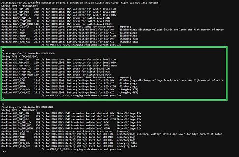
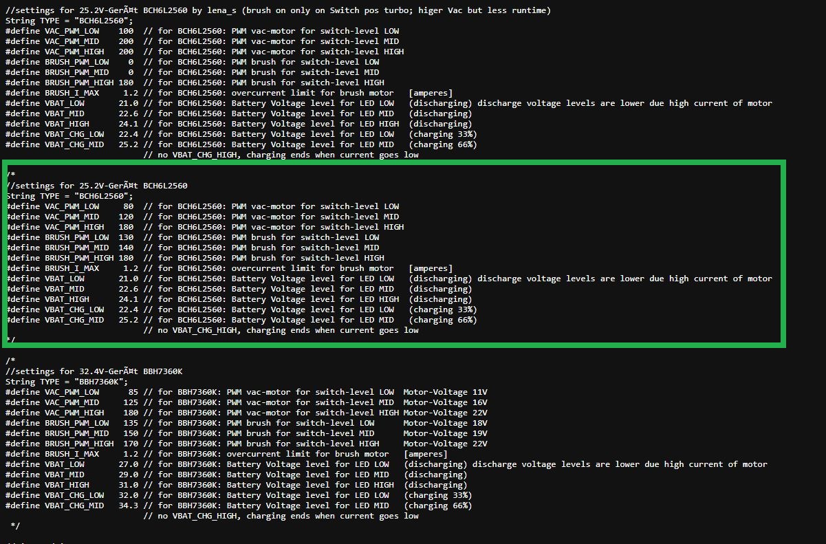
switch-level MID #define BRUSH_PWM_HIGH 180 // for BCH6L2560: PWM brush for switch-level HIGH #define BRUSH_I_MAX 2.0 // for BCH6L2560: overcurrent limit for brush motor [amperes] #define VBAT_LOW 21.0 // for BCH6L2560: Battery Voltage level for LED LOW (discharging) discharge voltage levels are lower due high
Ruckmeldung Eingang 1 “Steuerungstbetriebs- 1 bereit” I l l I L 1 2 3 2 t I 3 2 I 14 l I I I I I I I q max. 174ms max. 124~s Zeit Bemerkung Fehlermeldung l I 1 STROMUNTERBRECHUNG I 2 Yarten auf Steuerspannung STEUERSPANNUN FGUERRELAIS FEHLT 3 Nach Abschalten des Ausgangs “Steuerung betriebsbereit” muß innerhalb
10,000 Cycles Contact position indicator Yes Protection degree IP20 Ambient temperature -5℃ to +40℃, Max.95% humidity Terminal connection type Cable/Pin-type busbar/Fork-type busbar 2 Max.terminal size for cable 25mm Max.tightening torque 2.5N.m Installation Mounting on 35mm DIN rail Connection From top
den Nennvolumenstrom. Folgende Richtwerte sollten dabei nicht überschritten werden: dp = 120 Pa/m max von Rohrleitungen DN 10 bis DN 65 w max = 0,7 m/s von Rohrleitungen DN 80 bis DN 125 w max = 1,2 m/s ab Rohrleitungen DN 150 w = 2,0 m/s max Subject to change and error 20/327 Version 11/2021 Abb. 0.8
which has two extreme values along the hysteresis curve Bx,1− B x,2 B x,1− B x,2 µmin = min , and µ max = max . (5.58) H x,1Hx,2H x,1− H x,2 Hx,1,Hx,2H x,1− H x,2 Hereµ min andµ max aretheminimumandmaximumslopeofthehysteresischaracteristics. The inequality µmin ≤ µ ≤ µ max (5.59) is obvious, from which
Power 400W Package Outline Dimensions DO-214AC (SMA) HE SMA (DO-214AC) E DIM Millimeters Inches Min. Max. Min. Max. A 1.90 2.30 0.075 0.091 B D A1 0.00 0.20 0.000 0.008 B 1.25 1.65 0.049 0.065 cathode band C 0.15 0.31 0.006 0.012 D 2.35 2.90 0.093 0.114 E 3.99 4.60 0.157 0.181 HE 4.80 5.30 0.189 0.209
nicht-sinusförmigem AC damit noch keine Erfahrungen. Anderes billig-DMM ------------------ U_netz = 233 V I_max = 1,30 A (150V*1,5A = 225W P_out) P_in = 303 W Auh weih... welchem soll man glauben?
magnetische Kopplung vs. 2x Isolation? Wenn man vergleicht, Branadics 45VA hat bei 4 Stück je 135 Euro gekostet. Bei einem der Selbstbau-Audio-Shops habe ich einen EI120/73-Trafo-Bausatz für ca. 90 Euro gesehen, finde es aber gerade nicht.
IP65 4,21€ für Platinen Pulserzeuger 80x60x1,5mm 1€ und für LED-Anzeige BY428V Ri2M, 70x50x1,5mm 1€ max.350Vs R31=33k 0,6W 350V Metallschicht max.3000Vs R31=10M 0,5W 3500V Glas D4x10mm VR37 3357799 Farnell Vishay oder RL40 high voltage resistor Glas 2W 2000V 3000Vmax D5,8x15mm Ali 2,24€/10 Material
Metallschicht 0,6W haben nur max. 350V evtl. 2x in Reihe verwenden) Als Thyristor besser TYN612 600V 8-12A 120Apk@10ms Ig15mA Ih30mA Rth=2,5°C/W TO220 1,85€/10 verwenden wegen höherem I-Haltestrom (dann R5min <100k möglich wird,
cycles D and D are less than D . In this case, the first, simple equation can always be used. 1 2 MAX 2. One duty cycle is greater than D MAX and the other duty cycle is less than D MAX . In this case, the system designer can take advantage of the fact that the sync feature reduces D MAX for one channel
Bodydiode kann als Freilaufdiode in H-Brücken verwendet werden 2. Durchbruch bei Überschreiten der max. Drain-Source Sperrspannung zerstört das Bauteil nicht, wenn der Strom sowie die Energie begrenzt werden. (Verhalten wie Z-Diode) Nachteile Antiparallele Diode (Bodydiode) ist in nahezu allen MOSFETs
Rolle spielen, bist du schon am Ziel angelangt. Würde deine LED 100mA statt 20mA benötigen, wären die max. 100mA des BC547 etwas knapp bemessen. Du blätterst also in der Reichelt-Liste weiter und stößt auf den BC337-40 mit 45V, 0,5A und 0,525W. Das ist genau das, wonach du suchst. Bei diesem Transistor
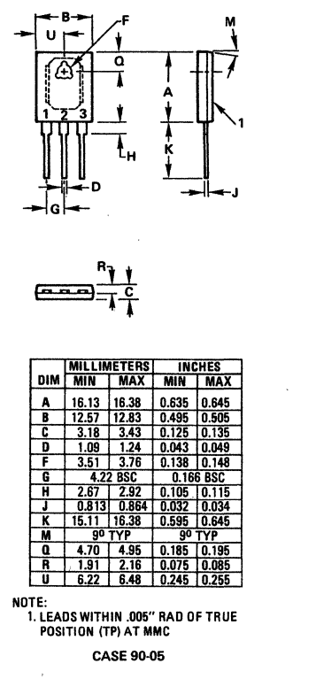
B F U Q A M K J D G H R C
MILLIMETERS INCHES
DIM MIN MAX MIN MAX
A 16.13 16.38 0.635 0.645
B 12.57 12.83 0.495 0.505
C 3.18 3.43 0.125 0.135
D 1.09 1.24 0.043 0.049
F 3.51 3.76 0.138 0.148
G 4.22 BSC 0.166 BSC
H 2.67 2.92 0.105 0.115
J 0.813 0.864 0.032 0.034
USB-C ist dagegen für die angestrebte Nutzung ziemlich egal, ersteres gibt es auch als THT. Grüße Max
Max G. schrieb im Beitrag #7716530: > Glückwunsch, das sieht doch mal gut aus! Danke. :-) Max G. schrieb im Beitrag #7716530: > Woher kommen denn die Blasen im Lötstopp? Das sind nur Flussmittelreste
2 oz. (610 g/m ) copper clad. Conditions Parameter Symbol SOURCE = 0 V; T = J40 to 125 °C Min Typ Max Units See Figure 18 (Unless Otherwise Specified) CONTROL FUNCTIONS T = 25 °C Average 124 132 140 Output Frequency fOSC J kHz See Figure 4 Peak-Peak Jitter 8 Maximum Duty DC MAX S1 Open 62 65 68 % Cycle
home’s drain to which the drain hose is attached. Laundry tub about 100 cm Hose Retainer about 145 cm Max. 100cm Max. 100cm strap m 0 1 about 105 cm a m In this type of drain hose installation, the odor could be coming from the standpipe. This odor can come up the drain hose and into the unit. Pour a cup
SUBPART J APPLICABLE AT THE DATE OF MANUFACTURE. COMPLY WITH DHHS RULE 21 CFR CAMBRIDGE, CB5 9PB. MAX WARNING: THIS APPLIANCE MUST BE EARTHED. Amplifier Board L924 Contents Circuit description Component overlay Parts list Circuit diagrams The line ‘NFB’ provides for a portion of the negative feedback
1.5 m/s Voltage range VDC 8.5 - 17 (compressor compartment temperature equal to ambient temperature) Max. condensing temperature continuous (short) °C 60 (70) Max. winding temperature continuous (short) °C 125 (135) F2 = Fan cooling 3.0 m/s necessary SG = Suction gas cooling normally suffjcent – = not
switch-level MID #define BRUSH_PWM_HIGH 180 // for BCH6L2560: PWM brush for switch-level HIGH #define BRUSH_I_MAX 2.0 // for BCH6L2560: overcurrent limit for brush motor [amperes] #define VBAT_LOW 21.0 // for BCH6L2560: Battery Voltage level for LED LOW (discharging) discharge voltage levels are lower due high
switch-level MID #define BRUSH_PWM_HIGH 180 // for BCH6L2560: PWM brush for switch-level HIGH #define BRUSH_I_MAX 2.0 // for BCH6L2560: overcurrent limit for brush motor [amperes] #define VBAT_LOW 21.0 // for BCH6L2560: Battery Voltage level for LED LOW (discharging) discharge voltage levels are lower due high
switch-level MID
#define BRUSH_PWM_HIGH 130 // for BCHL2560: BRUSH for switch-level HIGH
#define I_MAX 1.2 // for BCHL2560: overcurrent limit for brush motor [amperes]
#define VBAT_LOW 24.6 // for BCHL2560: Battery voltage level for LED LOW (discharging)
#define VBAT_MID 22.6 // for BCHL2560: Battery
behavior. The 5.3 Write-heavy Applications S6 model used in our experiments has 32 GB of capacity and a max- Apps excluded from this study may still issue exceptionally high imum two year warranty [122]. According to our measurements, the minimum volume of writes required to consume 10% of the S6’s write
to to to to 18.7 x 18.7 mm 2 32 x 32 mm 2 13 x 13 mm 2 55 x 55 mm 2 20 x 20 mm 2 92 mm edge length Max. component height 6 mm 8.5 mm 8.5 mm 20 mm c 20 mm c Max. component weight 2 gr 5 gr 5 gr 25 gr 25 gr Placement force 2.4 - 5.0 N 2.4 - 5.0 N 2.4 - 5.0 N 1 - 10 N 1 - 10 N Performance 11,000 cph 8,500
current C 1.5 A Collector peak current pt < 1ms) I 3 A CM Maximum junction temperature T 150 °C J MAX Storage temperature T -55 to 150 °C STG Notes: 1. Limited by maximum junction temperature. R ev. 0.3 iW1817 P age 3 iW1817 Product Brief Off-Line Digital Green-Mode PWM Controller Integrated with Power

 Bild
Bild
 Bild
Bild