Symbol Parameter Part Number Min. Typ. Max. Unit TBU-CAxxx-050-WH 50 75 100 TBU-CAxxx-100-WH 100 150 200 I Current required for the device to go from operating state to TBU-CAxxx-200-WH 200 300 400 mA trigger protected state TBU-CAxxx-300-WH 300 450 600 TBU-CAxxx-500-WH 500 750 1000 Vimp = 250 V Itriggermin
0.7µV/°C x = –32.7µV x = –1.5µV σ = 0.5µV/°C 300 σ = 109.4µV σ = 17.9µV S R T I 40 N250 I U P G M I200 A 30 R O B R M150 E U B 20 N U 100 N 10 50 2 0 1 0 - –2.8 –2.2 –1.6 –1.0 –0.4 0.2 0.8 1.4 2.0 2.6 3.2 3.8 - –600 –400 –200 0 200 400 600 6 6 INPUT REFERRED OFFSET VOLTAGE (µV) 1 INPUT OFFSET VOLTAGE
version of the specification. The version of the product specification will be updated in time.Please refer to the latest information on the official website; *The copyright and the final interpretation right of the product belong to Dongguan opsco Optoelectronic Technology Co., Ltd. if you have special
mich, wie es dann sein kann, solch ein Netzteil zu verkaufen: https://www.amazon.de/dp/B0D624ZM4F?ref=fed_asin_title&th=1 Dieses hat 6A/24V. Es sollte doch möglich sein, eine passende Buchse dafür zu finden, die das kann. Ich muss doch auf die Angaben des Herstellers vertrauen können, wenn die Buchse
Vorschlag: https://www.meanwell.com/webapp/product/search.aspx?prod=LRS-100 (bei Bedarf auch 150/200/250W Versionen erhältlich). Bei A* werden dafür 24€ aufgerufen. Dafür kannst Du das nicht selber machen. Alternativ: Das RD-125B gibt einmal 5V@4.6A und einmal 24V@4.6A aus. https://www.meanwell.com
Smart Start™ NXT Boxes Dimensions of Housing (W x H x D) 11-13/16" x 19-11/16" x 7-7/8" (300 x 500 x 200mm) without wall brackets Installation Vertical using wall bracket on housing bottom Supply voltage via L1, L2, L3, PE 1PH/3PH 230VAC ±10% 50/60Hz Wye Systems Only Fuse ▯▯$▯&ODVV▯&& Control Power Consumption
keine plausiblen Werte an, es ist halt eine Glimmlampe. Ein Isolationstester zeigt mir bei 250V DC ca. 200k an. Bei meinem Schalter ist die Glimmlampe direkt mit den Anschlüssen verbunden, leuchtet also wenn man an die „Ausgänge“ des Schalters Spannung anlegt.
change 30 Hz to 200 MHz ±0.5 V ±5 V ±50 V dc Offset Range ±20 V ±200 V ±500 V Input Impedance Resistance 1 MΩ 9 MΩ 10 MΩ Capacitance 7 pF 3.5 pF 2 pF ac Low-freq. Response (-3dB) 15 Hz 1.5 Hz 1.5 Hz dc Reject Response
is available in an 8-lead TO-99, and a 10-pin 400 mA pulsed output current Y Slew rate is typically 200 V/ms molded dual-in-line package. Y Operation fromg 5V tog 20V The LH0002 is specified for operation over 55§C to a 125§C military temperature range. The LH0002C is speci- fied for operation over§the
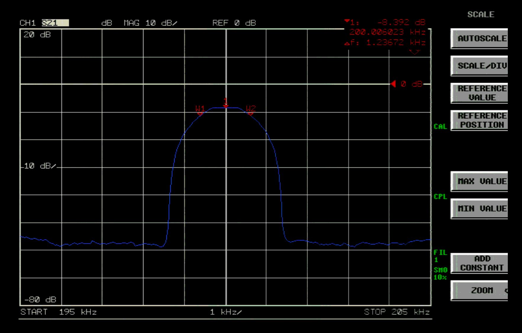
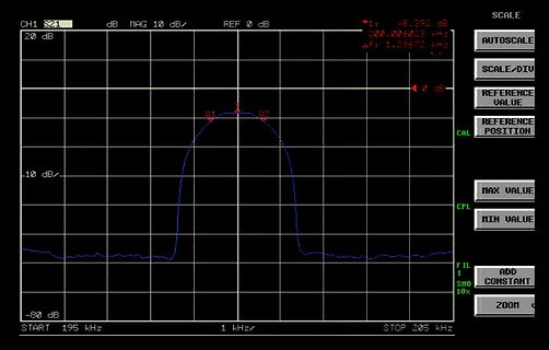
CH1 S21 dB MAG 10 dB/ REF 0 dB
1: -8.392 dB
200.006023 kHz
Δf: 1.23672 kHz
0 dB
20 dB
-10 dB/
CAL
REFERENCE POSITION
MAX VALUE
MIN VALUE
CPL
FIL
1
SMO
10%
ADD CONSTANT
ZOOM
-80 dB
START 195 kHz
1 kHz/
STOP 205 kHz
(Insulation Thickness) ≥0.4 mm TS Case Temperature (Note 1) 150 °C IS,INPUT Input Current (Note 1) 200 mA PS,OUTPUT Output Power (Note 1) 300 mW R Insulation Resistance at T ,= 500 V (Note 1) >109 IO S IO 1. Safety limit values – maximum values allowed in the event of a failure. www.onsemi.com 2 HCPL0453
Petcr Edelmann Nf·Stereo·Einstellschaltkreis A H14 D Ing. HclmutJahn Doppel-NF.Leislungsverslirker A 200fJ VIA 20()j V MotklTK: ,nlc~ne Scllallklel>C"HunJlunken,pbn~, HorSl Junlll'nlla .- 2.,be.ichllllAufl.• - Ocrh..; M,IIlIi,verlag ,kr 1)I)R (VEBt l'ISIl. 115S . 5.l ß,llI(dcclron;c3' 24]) ISBN 3-327-(
UVLO L 7 8 9 V Start-up current I V =10V 50 95 125 μA START CC Operating current VCC CS=1V 100 150 200 μA Protection current PRO CS=5V 800 1200 2000 μA CC parameters CS reference voltage CS REF 388 400 412 mV CS peak protection voltage CS PEAK 450 550 650 mV Time Parameters Max. on time TON,MAX 30 38
CONDITIONS MIN TYP MAX UNIT LM1117-ADJ 1.238 1.25 1.262 OUT = 10 mA, VIN – VOUT = 2 V, J = 25°C V REF Reference voltage LM1117-ADJ TJ= 25°C 1.25 V 10 mA ≤ I ≤ 800 mA, 1.4 V ≤ OUT over the junction temperature range 1.225 1.27 VIN– VOUT ≤ 10 V 0°C to 125°C LM1117-1.8 1.782 1.8 1.818 OUT = 10 mA, VIN
the region around the exciter position, with a a detailed discussion on edge boundaries for MAPs, refer to [39]. diameter of a few centimeters due to the high internal damping The simulation results showed some areas, where to put the LF of the panel. As a result, the optimal excitation points cannot
output current reaches 1.3A and the maximum peak output current reaches 3A. — 3V drive signal average 200uA input current This circuit is a power device, which has a certain internal resistance. ÿ Built-in thermal protection circuit (TSD) with hysteresis effect The heat generation is related to the load
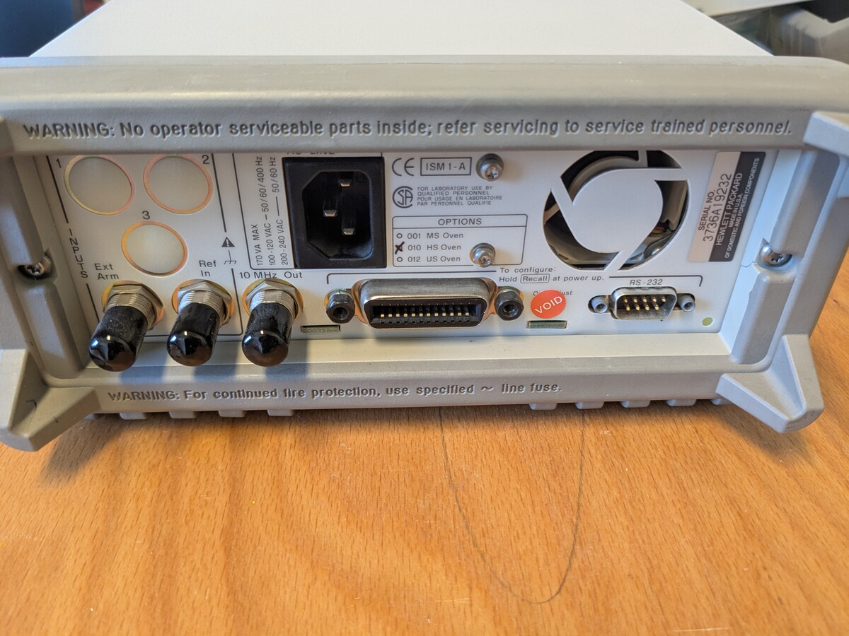
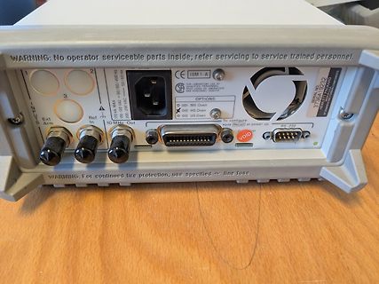
WARNING: No operator serviceable parts inside; refer servicing to service trained personnel. 2 3 INPUTS Ext Arm 170 VA MAX 100-120V 50/60 Hz 200-240 VAC 10 MHz Out Ref In CE ISM 1-A OPTIONS 001 MS Oven 010 HS Oven 012 US Oven To configure: Hold Recall
gestattet bis zu +/-275V am Eingang: https://www.ti.com/lit/ds/symlink/ina149.pdf?ts=1752847380751&ref_url=https%253A%252F%252Fwww.google.com%252F Mit GND als V- ist Dein Common Mode Bereich quasi -0V..+60V.
TI iso124 oder Analog AD215 Oder mit differntiellen bzw. symmetrischen Optokoppler wie dem HCNR200, damit kann man max Bandbreite (Datenblatt) von 1.5 MHz erreichen, aber weniger genau. Damit kann man potentialfrei messen und die Einschränkung Common Mode gibt es nicht, nur Isolationsspannung
with good thermal conductivity and long-term endurance should be applied evenly with about +100μm~+200μm on the contacting surface of DIPIPM and heat sink. The contacting thermal resistance between DIPIPM case and heat sink Rth(c-f) is determined by the thickness and the thermal conductivity of the applied
und freien PLL-Einstellungen wird die Kurve deutlich schärfer: RP2040 PLL-VCO läuft mit 1,5 GHz. RefDiv = 2, FBDIV = 250, POSTDIV1 = 3 und POSTDIV2 = 2. Das Bild ist mit mit dem Rigol Tastkopf PVP2350 und 10:1 Teiler und Massefeder entstanden.
finde werde ich noch niederohmigere Teiler als 450R+50R ausprobieren, die Widerstandskombinationen 200R+22R und 91R +10R liegen schon bereit.
needed to dissipate 1mW through the reference impedance is applied. The relationship between dBm, a refer - ence impedance, and the voltage is defined by the following equation: ⎛V2 /Z ⎞ ⎝ IN REF ⎠ dBm = 10 log ---1mW------------------------ Where: V is the DC or AC input signal. IN ZREF is the specified
on OSD can be grouped to few rows, each row has its own row attribute (the high byte of Wohd #1F , ref. Section 0) which defines the behavior of current character row. And, there is maximum 30 characters in one row (Wordh#00 ~ h1D ), each character has two bytes to define its character font number (ref
The open-drain outputs directly drive the LEDs with maximum output sink current of 25 mA per bit and 200 mA per package (100 mA per octal). To blink LEDs at periods greater than 1.69 second the bus master (MCU, MPU, DSP, chip set, etc.) must send repeated commands to turn the LED on and off as is currently
SET1 = VCC, SET0 = CC Watchdog Disabled Startup Delay Period DELAY SET2 = V CC, SET1 = 0V, VSET0 = 0V 200 600 µs SET2 = V , V = 0V, SET0 = V First Edge (Note 3) CC SET1 CC SET2 = V CC, SET1 = CC , SET0 = 0V First Edge (Note 3) SET2 = V CC, SET1 = CC , SET0 = CC 60 180 s V SET2= 0V, VSET1= 0V, SET0 = 0V
programs (24 samples at a rate of one External Isco Nickel-CadmiumBattery 3 Note: Not certified by UL 200-ml sample per hour, using 10 ft. of /8-in. vinyl suction line at a 5-ft. head) External Isco Lead-Acid Battery 11 standard sampling programs (24 sampl3s at a rate of one 200-ml sample per hour, using
the transistor must not be R 2.0 subjected to greater dissipation than the curves indicate. T TJ= 200°C 100 ms E 1.0 1.0 ms The data of Figure 2 is based on T J(pk)= 200_C; T C L is variable depending on conditions. At high case C 0.7 CURRENT LIMIT 100 ms temperatures, thermal limitations will reduce
V C 0.2 , 0.2 F V @ I /I = 10 h CE(sat) C B 0 0.1 0.2 1.0 10 100 0.2 0.5 1.0 2.0 5.0 10 20 50 100 200 C , COLLECTOR CURRENT (mA) C , COLLECTOR CURRENT (mA) Figure 7. DC Current Gain Figure 8. “On” Voltage ) T 2.0 )-1.0 O ° ( TA= 25°C V E 1.6 (-1.4 A N L 20 mA 50 mA 100 mA 200 mA I V I E 1.2 F-1.8 T
LTD. 2024 SG-17VLZ Rating and Characteristic Curves 100 1.E-03 t =0.4 ms T = 235 °C J 1.E-04 10 TJ= 200 °C T = 235 °C ) ) J ( 1.E-05 ( IR TJ= 150 °C IF t t 1 r 1.E-06 e T J 200 °C u TJ= 100 °C u C C g r 0.1 T J 150 °C a 1.E-07 T J 60 °C a a r L F T J 100 °C s 1.E-08 e 0.01 e T J 25 °C T J 60 °C R 1.E-
Kiwi-Instruments-KP3114SGA_C554028.pdf Klasse. Chinesischer IC mit "ausführlichem Datenblatt". V_FB_REF ist scheinbar 1,78V. Dann wäre V_Out wohl: V_out = V_FB_REF * (R_FB1 + R_FB2) / R_FB2 R_FB1 und R_FB2 musst halt auf deiner Platine messen.
mir irgendwie nicht vorstellen. Dann käme mit > > Timo N. schrieb im Beitrag #7898399: >> V_FB_REF ist scheinbar 1,78V. >> >> Dann wäre V_Out wohl: >> >> V_out = V_FB_REF * (R_FB1 + R_FB2) / R_FB2 > > > für V_Out = 8,2V raus. Wäre zu hoch für den µC auf der anderen Seite. > Es sei denn
Switching low 650 μs Number of MCLKs preceding the release of PDN, see Figure 4 5 su Device startup time 200 µs Time to audio output 160 mS 6.11 Back-End Error (BKND_ERR) Control signal parameters over recommended operating conditions (unless otherwise noted) PARAMETER MIN TYP MAX UNIT w(ER) Pulse duration
Halogen • Low DCR; high current; shielded construction Free • Perfect for backlight applications • AEC-Q200 Grade 1 qualified (–40°C to +125°C ambient) AEC Designer’s Kit C349 contains 3 each of all values Q200 125°C Core material Ferrite Core and winding loss See www.coilcraft.com/coreloss Environmental
Ich habe eh einen 5V Spannungswandler verbaut - Vorsicht, Link: https://www.amazon.de/dp/B09B81M5T8?ref=ppx_yo2ov_dt_b_fed_asin_title&th=1 Dann würde ich den an den 5V-Eingang des ESPs anschließen, aber auch gern die weiteren Bauteile mit diesen 5V betreiben. Die sind wenigstens stabil, die Bordspannung
es ist Sommer) ausgehen, wird der Transistor also 530°C warm. Transistoren vertragen aber nicht mal 200 °C. Will sagen: Sämtliche Grenzwerte im Datenblatt sind immer nur einzeln betrachtet. Der Transistor verträgt 100mA, aber nicht bei 50V. Der Transistor verträgt 50V, aber nicht bei 100mA. Der begrenzende
Content: < 0.3g Operating Temp: -30C to 60C Self Discharge: ~1% / year 24.50 (0.965) 3.45 (0.136) Ref. 24.30 (0.957) 3.15 (0.124) Ref. Safety: R1.25 (0.049) Ref. 22.0 (.866) 1.00 (0.039) Ref. Max Minimum (1) KEEP OUT OF REACH OF CHILDREN. Swallowing may lead to R0.75 (0.030) Ref. serious injury or death
appropriate highest order vice identification, and sector protection verification, address bits. Refer to the corresponding Sector Ad - through identifier codes output on DQ7–DQ0. This dress Tables. The Command Definitions table shows mode is primarily intended for programming equipment the remaining
Ursprünglich sendete Droitwich auf 200 kHz außerhalb des ITU Rasters. Erst im September 1988 wurde auf die jetzige Sendefrequenz von 198 kHz umgestellt. Sowohl die 200 kHz als auch die 198 kHz sind von einem Rubidiumnormal synchronisiert
SW-Bluetooth-Radio-LED-Beleuchtung-wiederaufladbare-Unterst%C3%BCtzung-USB-MP3-Player-Blau/dp/B0DM1W8VYV?source=ps-sl-shoppingads-lpcontext&ref_=fplfs&smid=AKO0FL019F2AL&th=1 Jörg W. schrieb im Beitrag #7891045: > Was glaubst du, warum man hier wohl den Sendemast in Wilsdruff letztlich > doch abgerissen hat? SCNR: https://www.gofundme.com
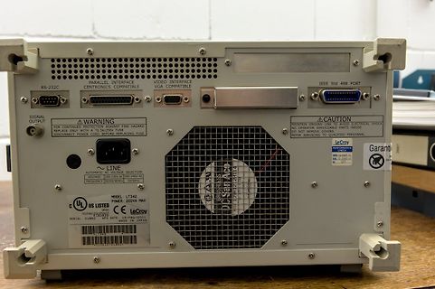
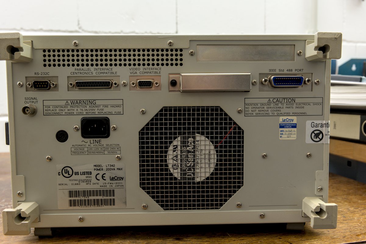
MAINTAIN GROUND LINE TO AVOID ELECTRICAL SHOCK NO OPERATOR SERVICEABLE PARTS INSIDE DO NOT REMOVE COVER REFER SERVICING TO QUALIFIED PERSONNEL LeCroy LINE AUTOMATIC AC VOLTAGE SELECTION 120V AC 200-240V AC VOLTAGE FREQUENCY 50/60Hz 50/60Hz MODEL LT342 POWER 200VA MAX UL US LISTED CE LeCroy MADE IN JAPAN SERIAL
160 168 1 219 2.7 0.108 140 P6SMB180AT3G 180A 154 5 171 180 189 1 246 2.4 0.108 130 P6SMB200AT3G 200A 171 5 190 200 210 1 274 2.2 0.108 115 6. A transient suppressor is normally selected according to the working peak rRWMr), which should be equal to or greater than the DC or continuous peak

 Bild
Bild
 Bild
Bild
 Bild
Bild
 Bild
Bild
 Bild
Bild
 Bild
Bild