
-
PDF
Navtex.pdf
channels, military stations for example. The 90° phase shift is carried out with two D-flip-flops (74HC74); in the process the VCO frequency is divided by 4. Oscillator frequencies fed to the mixers are 489.6 kHz (17 x 28.8 kHz) and 518.4 kHz (18 x 28.8 kHz). Since the oscillator operates below the input
-
PDF
schaltplan.pdf
1 2 3 VDD3V3 470 VDDLED VDD3V3 470 R23 R20 U4 R22 R21 CD74HC4050M96 D D D L R 0 E E 1 16 T 7 1 3 7 1 0 L 4 L 2 VCC N.C 15 I 4 R - 4 R - X D E X 3 1Y 6Y 14 _ 3 5 A T L L R 4 1A 6A 13 E GPIO2 LED 5 K A 5 2Y N.C/212 M LED6 1 C 2 X USB_TXD 6 2A 5Y 11 T E R E Y 7
-
PDF
ADT7301_-__1_C_Accurate__13_Bit__Digital_Temperature_Sensor__ADT7301.pdf
processors transfer SCLK P3.1 16 bits of data in a serial data operation. DOUT P3.0 ADT7301-to-MC68HC11Interface DIN P1.2 9 Figure 15 shows an interface circuit between the ADT7301 and 0 CS P1.3 8 the MC68HC11 microcontroller. The MC68HC11 is configured 0 in master mode with its CPOL and CPHA bits set
in „Implementierung eines ADT7301 an einem MSP430FR5729“ · Mikrocontroller und Digitale Elektronik ·
-
Datei
99geraete.txt
183 DT970 3.75 TSC820 TL062 TL062 TL062 CD4093 2-39b 29 183 DT970xx 3.75 TSC820 TL062 TL062 TL062 74HC14 2-40a 30 187 DT930F 4.5 ICL7129 ICM7556 TL062 ICM7555 CD4011 TL062 ICL8069 2-40b 31 187 DT930G 4.5 ICL7129 TL062 TL062 CD4011 ICM7556 ICL8069 LM358 2-40c 32 187 DT930F+ 4.5 ICL7129 LM358 TL062 CD4011
in „Suche Schaltplan / Bed-Anleitung Mastech M840D DMM gute Qualität“ · Mikrocontroller und Digitale Elektronik ·
-
PDF
MIC94030BM4.PDF
Pulse Test 6 1997 6-43 MIC94030/94031 Micrel Typical Applications SS* +5V S D MIC94030 G a On L Off 74HC04 * Substrate must be connected to source Figure 1. Power Switch Application +12V Internal Resistor G S Open Drain SS* Output MIC94031 D d a L * Substrate must be connected to source Figure 2. Power
in „MOSFET ohne Body-Diode“ · Analoge Elektronik und Schaltungstechnik ·
-
PDF
Reichelt_Input.pdf
: 1210865197 Artikel-Nr. Bezeichnung WG Menge Einzelpreis Gesamtpreis incl. MwSt. incl. MwSt. SL 1X40W 2,54 40pol. Stiftleiste, gewinkelt, RM 2,54 1 4 0,22 € 0,88 € SIL 9-8 10K Widerstandsnetzwerk, 10 kOhm, Sternschaltung, 8Wid./9Pins 1 4 0,11 € 0,44 € 74HC 14 6xINV.SCHMITT-TRIGGE 1 6 0,25 € 1,50 € ILQ 1 OPTOKOPPLER 1 8 0,99 € 7,92 € Warenwert 10,74 € ============ Zuzüglich Versandkosten innerhalb Deutschlands für ca. 0,0 kg 5,60 € Alle Preise in Euro inklusive gesetzl. Mehrwertsteuer. Mit freundlichen Grüßen Ihr reichelt elektronik Team von 1 09.10.2018
in „Open Source PLC/SPS nachbauen“ · Mikrocontroller und Digitale Elektronik ·
-
PDF
LT-097_manual.pdf
nicht direkt eingelötet werden, sondern auf den beiliegenden Sockel bestückt werden. Löten Sie den 40poligen IC Sockel direkt in die Platine und pressen Sie am Ende – kräftig, aber mit Gefühl – den Controller in den Sockel (Polung beachten!). Bauteile-Liste Bezeichner Anzahl Beschreibung Typ Bauform
in „Coole LED-Uhr gefunden - kennt jmd. einen gleichwertigen Nachbau“ · Mikrocontroller und Digitale Elektronik ·
-
PDF
Schematic.pdf
READ1_MCU GND 100nF 100nF 100nF 100nF 100nF AVCC a a a a a a a a a a a a a a a a a a a a a a a-7: 74C244 inputs PD2SYNCASYNCOC0CRXD0 29 READ2_MCU PD3SYNCOC0DTXD0 30 READ3_MCU GND READ0-7: 74C244 outputs PD4SYNCOC1ASS 31 READ4_MCU CARD_ADDRESSED: CD40107 Pin 5 output PD5SYNCOC1BXCK1MOSI 32 READ5_MCU
in „Problem mit CD4050B als Level Shifter“ · Mikrocontroller und Digitale Elektronik ·
-
PDF
PCF8574.pdf
Post Office Box 655303, Dallas, Texas 75265 Copyright © 2020, Texas Instruments Incorporated Nexperia 74HC11; 74HCT11 Triple 3-input AND gate 4. Functional diagram ▯ ▯▯ ▯ ▯$ ▯ ▯ ▯% ▯< ▯▯ ▯▯ ▯▯ ▯& ▯ ▯$ ▯ ▯ ▯% ▯< ▯ ▯ ▯ ▯ ▯ ▯& ▯ ▯$ $ ▯ ▯▯ ▯% ▯< ▯ ▯▯ ▯ % < ▯▯ ▯& ▯▯ & PQD▯▯▯ PQD▯▯▯ PQD▯▯▯ Fig 1. Logic symbol
-
PDF
Grundig-DVDP-7000-Service-Manual.pdf
AOL_O 10 Control D502 9 16 3 L504 FB300 CVBS/Y_O_J AOR_O 0(0805)/RLS4AR_I Y2 17 2 VIDEO_IN/OUT VDD 74HC02 Y1 18 1 CVBS D503 R434 SW SLIDE-6P2T 0(0805)/RLS4148 10K AOL_O AL_I If AV_SW=High,Then Input=AV_IN U501D If AV_SW=Low,Then Input=PLAYER 11 Speaker_Control 13 HP_IN3 VDD 12 HP_IN3 VDD 74HC02 J506
in „800x480-Farbdisplay mit uC verwenden“ · Mikrocontroller und Digitale Elektronik ·
-
PDF
Display_2_Parts_Top.pdf
0 8 8 1 LED1 R 5 R, R I 1 D 0 4 3 MC34063AP 4 1 4 1 12 Q L 1 100µ 6 3 3 JP1C 1 R 3 RB IC3 C11 D BAT40 4 R3 M 4 47µ 4 1 D4 2 N C 2 2 1 D 1 C12 H 1 Q X 7 2 74AC02N 7 K A I I S 2 Q1 R7 1 330 10 SV1 6 GND 1 Reset C I SCK MEGA8515-P MISO MOSI 2 1 S 1 S X - 1 2 F 5 Reset RXD TXD 0 9 0 1 0 R FRAME 3 GND R S R1S LOAD 6 CP I +5V GND -VEE D0 D1 D3 0 C 74AC573N 74HC157N D4 1 C C D. OFF I I M AC 100n C6 26.05.09 00:10 /home/kai/Desktop/Display_Controller_Grafik/DIP3/Display_2.brd
in „Grafikfähiger LCD Controller für 320x240 LCD mit 4 Graustufen“ · Projekte & Code ·
-
Datei
PSpice.ini
fontitalic=0 fontname=MS Sans Serif [PART LIBS] LIB1=1_shot [.slb , .plb] LIB2=7400 [.slb , .plb] LIB3=74ac [.slb , .plb] LIB4=74act [.slb , .plb] LIB5=74als [.slb , .plb] LIB6=74as [.slb , .plb] LIB7=74f [.slb , .plb] LIB8=74h [.slb , .plb] LIB9=74hc [.slb , .plb] LIB10=74hct [.slb , .plb] LIB11=74l [.slb , .plb] LIB12=74ls [.slb , .plb] LIB13=74s [.slb , .plb] LIB14=abm [.slb] LIB15=adv_lin [.slb , .plb] LIB16=analog [.slb , .plb] LIB17=analog_p [.slb] LIB18=ana_swit [.slb , .plb] LIB19=anlg_dev [.slb , .plb] LIB20=anl_misc
in „new Pspice version suckz: Model used by is undefined“ · Analoge Elektronik und Schaltungstechnik ·
-
PDF
IDE11.PDF
reprogrammieren (die ggf. angezeigte Fehlermeldung beim Verifizieren kann man aus o.a. Gründen ignorieren). 40 IDE11 V2.3 Benutzerhandbuch 4.8. Options 4.8.1. Target Dieser Menüpunkt dient zur Auswahl des angeschlossenen HC11-Target. Es erscheint eine Auswahlliste mit den zur Verfügung stehenden Zielsystemen,
in „Programm zum MC68HC11 auslesen und programmieren“ · Mikrocontroller und Digitale Elektronik ·
-
PDF
3d_drucker_print_v16.pdf
V 5 E2 Y6 9 E E E E E E 330 6 E3 Y7 7 S S S S S S 8 D +12V GND GND G JP34 JP37 JP39 JP41 JP43 JP45 74HC138N 1 1 1 1 1 1 9 K 2 2 2 2 2 2 2 D R 2 2 N 1 +5V G + JP36D-1X2 JP38D-1X2 JP40D-1X2 JP42D-1X2 JP44D-1X2 JP46D-1X2 BUZZER GND GND 1 1 1 1 1 1 2 2 2 2 2 2 U$2 16 VCC +12V PINHD-1X2 PINHD-1X2 PINHD-1X2
in „Eigenes 3D-Drucker Board - Viele Fragen“ · Mikrocontroller und Digitale Elektronik ·
-
PDF
HFKP.pdf
7C: E9 8D7F: A7LDIH Thcn@ gg Nonfch_ Dcg_hmcihm HFJO5,,,37,7,,/WWW0 894;g[r [ g > 7 748 94; 64| 748 74< 64> 7?g[r HFJO5,,,37,8,,/WWW0 88g[r 8<4;g[r r g 9 4 6 8 < 9 748 748 74< 64> HFJO5,,,37,9,,/WWW0 8:g[r [ g > 7 74; 94; 64| 748 74> 64> 7?g[r HFJO5,,,37,:,,/WWW0 88g[r 8<4;g[r [ | 9 6 8 8 4 9 74; 748
in „Suche Alternativ Relais zu YH 119 / 012-1h11-1s“ · Analoge Elektronik und Schaltungstechnik ·
-
PDF
MachXO2FamilyDataSheet.pdf
1280 2112 2112 4320 6864 Distributed RAM (kbits) 2 5 5 10 10 16 16 34 54 EBR SRAM (kbits) 0 18 64 64 74 74 92 92 240 Number of EBR SRAM Blocks (9 kbits/block) 0 2 7 7 8 8 10 10 26 UFM (kbits) 0 24 64 64 80 80 96 96 256 2 Device Options: HC Yes Yes Yes Yes Yes Yes Yes Yes Yes HE3 Yes Yes Yes Yes 4 ZE Yes
in „Statemachine springt in falsche "states" warum?“ · FPGA, VHDL & Co. ·
-
PDF
ADC_ApplicNotes.pdf
kHz for the –20 AD7710). Figure 5 shows this frequency response for the frequency ranges 0 kHz to 40 kHz, 0 kHz to 80 kHz, 0 kHz –30 to 160 kHz and 0 kHz to 320 kHz. Combining these plots with those of Figure 4 gives the overall frequency –40 response of the device, shown in Figure 6. –50 320kHz 0 d. Gain = 8–128 Figure 4. Frequency Response of PGA –2– 0 0 –50 –50 –100 –100 –150 –150 –200 –2000 40kHz 0 40kHz a. 0–40 kHz a. Gain = 1 0 0 –10 –50 –100 –100 –150 –150 –200 –200 0 80kHz 0 80kHz b. 0–80 kHz b. Gain = 2 0 0 –50 –50 –100 –100 –150 –150 –200 0 160kHz –200 0 160kHz c. 0–160 kHz c. Gain =
in „ADC-Überspannungschutz mit Z-Diode; Einfluss auf die Messgenauigkeit“ · Mikrocontroller und Digitale Elektronik ·
-
PDF
ccba_lago_0321_gb.pdf
74 T-Flow Cooling 0, 1, 15.0–25.0 °C 15.0 °C 35 Hysteresis time 0–30 min 0 min 75 T-Room Cooling ----, 20.0–40.0 °C 25.0 °C 36 Burner starts Display only 76 Min TO Cooling ----, 0.0–40.0 °C 27.0 °C 37 Burner
-
PDF
catalog.pdf
PCB ; Green; 0.63mcd; 3mm; T-1; 7mA; 1.9V; 565nm; 25deg; GaP on GaP; 20V; 20mW; -40 Latches and Flip Flops MPN: 74HC573D [ID]: 000135 [Price]: 0.34 USD [QTY]: 3 Page 46/87 Bauteileliste vom 12.08.2022 [Category]: Latches and Flip Flops [Desc]: Latch Transparent 3-ST 8-CH D-Type 20-Pin
-
PDF
catalog.pdf
PCB ; Green; 0.63mcd; 3mm; T-1; 7mA; 1.9V; 565nm; 25deg; GaP on GaP; 20V; 20mW; -40 Latches and Flip Flops MPN: 74HC573D [ID]: 000135 [Price]: 0.34 USD [QTY]: 3 [Category]: Latches and Flip Flops [Desc]: Latch Transparent 3-ST 8-CH D-Type 20-Pin SOIC Logic Gates MPN: SN74LVC1G32QDBVRQ1
-
PDF
catalog-3.pdf
; PCB ; Green; 0.63mcd; 3mm; T-1; 7mA; 1.9V; 565nm; 25deg; GaP on GaP; 20V; 20mW; -40 Latches and Flip Flops MPN: 74HC573D [ID]: 000135 [Price]: 0.4685 USD [QTY]: 3 [Category]: Latches and Flip Flops [Desc]: Latch Transparent 3-ST 8-CH D-Type 20-Pin SOIC Logic Gates MPN: SN74LVC1G32QDBVRQ1
-
PDF
217369.pdf
BulkResistance................15Milliohms@30millivolts 0 • 8000SeriesminiaturestyleisdesignedtoaccommodateHC-6/µ, CapacitancetoGround 5 HC-13µHC-14/µ,HC-27µ,HC-36/µandHC-48/µ crystalsizes (Contactto : HoldingClip) ................5pF@1,000Hz c • 8004SeriessubminiaturestyleisdesignedtoaccomodateHC-18/µ, f HC
in „Kühlkörper TO3 Befestigungslöcher zu groß?“ · Mechanik, Gehäuse, Werkzeug ·
-
PDF
DS1000Z_Analog.pdf
PIR4202 COR40 COR4 COR5 DAC_TLC274IPWR PIR401 PIR40P2IU309 PIR402 DAC_TLC274IPWR2 PIR501 TLV272IDGK COR3 COR6 R43 10 5 PIR302 PIR301 PIR602 PIR601 1K B R9 8 R7 VCOM_CH2 R10 7 R8 VCOM_CH4 COR41 B VREF_BUF 9 100Ω VREF_BUF
in „Analogverstärker für Mikrocontroller Oszilloskop“ · Analoge Elektronik und Schaltungstechnik ·
-
PDF
3B036723d01.pdf
(RQpinonly) VIN VSS0.5to2V DD.5 V Operatingtemperaturerange TA TLtoTH —Standard(MC68HC705B16) 0to+70 —Extended(MC68HC705B16C) —40to+85 ¡C —Industrial(MC68HC705B16V) —40to+105 —Automotive(MC68HC705B16M) —40to+125 Storagetemperaturerange TSTG —65to+150 ¡C (2) Currentdrainperpin(excludingVDDandVSS
in „unbekanntes Touchpad, wie anschliessen und verwenden?“ · Mikrocontroller und Digitale Elektronik ·
-
PDF
AD7302.pdf
. . . . . . . . . . –0.DDV+ 0.3 V θ JAThermal Impedance . . . . . . . . . . . . . . . . . . . . . 74°C/W Lead Temperature, Soldering Operating Temperature Range Commercial (B Version) . . . . . . . . . . . . . –40°C to +105°C Vapor Phase (60 sec) . . . . . . . . . . . . . . . . . . . . . . .+215°C Storage
in „(S) AD7302BNZ DAC DIP20“ · Markt ·
-
PDF
DSO203.pdf
X1 11 3 AIN S1 26 11K 1 3 3 K 3 X3 X0 X0 X3 R29 R31 1 AIN NC 36 L10 R42 Ain 10V 3 OPA2354 R7 R9 2 3 74HC4052PW 74HC4052PW 12K 12K 4 GND NC 35 2V8 L1 3K3 4K7 R17 R21 C21 12 DFS NC 46 2V8 FB R5 R5A C19 C17 GND VDD FB 105 105 22uF/6.3V 16 GND VDD 33 R47 27 GND AD9288-40 VDD 28 51R 29 15 5 L2 C18 C20 C22
in „Welches aktuelle DSO ist gut ?“ · Mikrocontroller und Digitale Elektronik ·
-
Datei
Gal_a.c
www.mino-elektronik.de http://www.bigmessowires.com/ http://www.demandperipherals.com/docs/CmdLineFPGA.pdf 74HC595 ,4015 ShiftReg. */ #define IBM #include <stdio.h> #include <ctype.h> #include <dos.h> #include <string.h> #include <dir.h> #ifndef IBM #define VIAPORTB *(char*)0xFFFF8801 #define VIAPBDIR *(char
-
PDF
K1000uC_rev11_Schaltplan.pdf
Stromversorgung Reset-Schaltung K5 1 2 VCC IC7 ~ B40C800 IC8 VCC LM1117T-3.3 R9 Display- - 10K + Steckverbinder 9 8 7 6 5 4 3 2 1 0 1 1 1 1 1 1 c c c c c c c c c c c c c c c c K1 C12 + +C13 + C14 I U N C7 K6 K9 ~ 10µF O G 10µF 100µF K2X17 100nF 1 2 /RESET
in „Atmega 1284p, Gelegentlicher Absturz bei Einstecken SD-Karte“ · Mikrocontroller und Digitale Elektronik ·
-
PDF
Hongfa__HF32FA-G_en.pdf
D_nq__h ij_h ]ihn[]nm 7666WCE7gch g[r4 gch4 9 848; 647; ;47 9> r /7 76-0 Pj_l[n_ ncg_ /[n higc4 pifn40 >gm g[r4 ; 94=; 648; >4; 76> r /7 76-0 S_f_[m_ ncg_ /[n higc4 pifn40 :gm g[r4 < :4;6 6496 7648 7;; r /7 76-0 Jogc^cns ;- ni >;- SJ Cg\c_hn n_gj_l[nol_ 3:6 ni >; ? <4=; 64:; 7;49 9;6 r /7 76-0 Hoh]ncih
in „Relais Hongfa HF32FA-G: Strom bei induktiver Last?“ · Analoge Elektronik und Schaltungstechnik ·
-
PDF
Vergleichsliste.pdf
ECG262 T1P126 2SB791 T1P127 ECG263 D44E3 TIP102 2N6387 2SD635 ECG264 D45E3 TIP107 2N6668 2SB886 ECG265 D40C7 ECG266 D40C8 ECG267 D40C3 ECG268 D40K2 ECG269 D41K2 ECG270 T1P140 T1P141 T1P142 ECG271 T1P145 T1P146 T1P147 ECG272 MPSU45 ECG273 MPSU95 ECG274 2N6295 ECG275 2N6297 ECG276 SG613A ECG277 2SC1034 2SC1316
in „ECG45 was ist das?“ · Analoge Elektronik und Schaltungstechnik ·
-
PDF
HausAutoTest1808.pdf
8C 11 3 D4 R27 B 6 CAN_GND QH 7 2 LED B J D 7 10k U18 9 2 1 HI CAN_H R18 9 1 S 8 CAN_L QH D5 P8 9 74HC595 GND P1 C40 1 2 C37 C39 GND 3 4 C38 GND GND GND V GND 100n 5 6 5 100n 100n 100n CAN 2 5 0 3V3 CON1 GND U15 1ULN2803 11 0 R 1 MAX3378 0 k MOSI0 14 15 1 18 10 1 2 1 VL VCC 14 9 DAT2 R 1 SER QA 1 2
in „Layout prüfen“ · Platinen ·
-
PDF
CMAC_Xtal.pdf
A118C 35.25120MHz HC49/4H 15/30/20/18 3rd XTAL003371 A216K 3.579545MHz HC49/4H 30/50/20/20 XTAL003063 A119K 40.320MHz HC49/4H 30/50/10/18 3rd XTAL003379 A220H 3.68640MHz HC49/4H 30/50/20/30 XTAL003263 A169K 4.0MHz HC49/4H
-
PDF
z80_peripherie.sch.pdf
pwr 0 sup 0 N C a a a G PA[0..7],PB[0..7],PC[0..7] V IC1 p p p p s SV4 D0 io 08 D0 CLK0 9 in 0 PB4 74HC165N 3 pas 1 D1 io 07 11 in 0 PA4 0 74HC151N 1 in 0 5V 27 2 pas 1 io 06 D1 GATE0 10 out 0 p 7 in 0 SH/LD 15 in 0 C A PIO7 26 D2 D2 OUT0 PIO6 6 G PA0 INH C LED8 A 1 pas 1 D0 D3 io 05 D3 1 C C 9 in 0
in „Retro Fieber: Z80 oder 68000 ?“ · Mikrocontroller und Digitale Elektronik ·
-
PDF
Hantek_Tekway_DSO_front_panel_and_flow.pdf
A 55 P 44 UF3PIKF2101 PIKF21020 CRF4 1k 2 1RotaryEncoder Utility Cursor Display Single Seq SW-PB SN74HC595N S S F0 UF3PIKF801F PIKF802X2 UF3XPIKF1201PIKF1202X2 UFPIKF27017PIKF2702X2 UF3PIKF17011PIKF17020 CH1 LED DF1616 PIUF407' GND PIUF40GND COKF9 A C B SW-PB SW-PB SW-PB SW-PB PIDF1602 PIDF160PIRF2021
in „TEKWAY DST1xx2B Oszilloskop“ · Mikrocontroller und Digitale Elektronik ·
-
PDF
Disp14SegSch.pdf
1 2 3 4 5 6 7 8 VCC VCC IC1 74HC595 VCC 16 IC2 74HC240 8 VCC 15 2 18 RN1D DDAT 14 QA 1 4 1A1 1Y1 16 10K T7 DCLK 11 SI QB 2 6 1A2 1Y2 14 BLANK V9P06 DSTB 12 CLK QC 3 8 1A3 1Y3 12 7 9 STB QD 4 11 1A4 1Y4 9 SO QE 2A1 2Y1 13 OE QF 5 13
in „Achtung, Newbie, LED-Ansteuerung“ · Mikrocontroller und Digitale Elektronik ·
-
 Bild
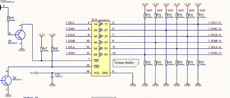
Schaltplan eines 74HC365PW Tristate Buffers
74AHC1G08GV,125,R58,10kOhm,Q5,BSS64AT116,GND,+3.3V,+3.3V,R47,10kOhm,R48,10kOhm,I INLC,2,1A,3,1Y,3,I INHC,5,2Y,5,I INLB,6,3A,7,I INHB,10,4A,9,I INLA,12,5A,11,I INHA,14,6A,13,I INHA O,1,OE1,IC11,74HC365PW,118,6Y,15,OE2,16,GND,VCC,R38,100Ohm,R39,100Ohm,R40,100Ohm,R54,100Ohm,R55,100Ohm,R56,100Ohm,I INLC O,I INHC O,I INLB O,I INHB O,I INLA O,I INHA O,Q6,BSS64AT116,GND,+3.3V,C52,100nF/50V,GND
in „AND Gate mit Shutdown Problem“ · Mikrocontroller und Digitale Elektronik · · Schaltpläne
-
PDF
mirkonet_tmp.pdf
8,736 17,472 Farnell LGA-14 N/A 3 Axis Accelerometer, SPI, I2C, +-8g: 80mg/digit, +-2g: 20mg/digit N-40/+85 +/-100ppm/K N/A 2,16 3,6 3,3 N/A 1435588 100 74LOGIC SN74LVC373APWR TEXAS 74LVC373 LATCH YES YES 0,173 0,208 20,760 Farnell TSSOP-20 N/A LATCH,373, Octal D-Type, Transparent N/A -40/+85 N/A N/A 1,65
in „Komplettverkauf Bauteile, was wert? - Tabelle“ · Markt ·
-
PDF
com_en.pdf
data traffic of the FSBUS to the PC and the yellow LED data traffic of the PC to the FSBUS. N3 N6 (74 HC04) are used for the reinforcements of the bus signal. N1, N2 form the ISP connection together with J8 to the Flash of the Microcontroller. The components providing an early Reset signal when switching
in „Hilfe bei Schaltung“ · Mikrocontroller und Digitale Elektronik ·
-
Datei
peps_avr_v10.bas
' 2014 Werner Römer [werner.roemer@t-online.de] ' ' letzte Änderung ' 15.04.2014 Treiber IC7 durch 74HC541 ersetzt (nichtinvertierend) ' Routine zum Füllen mit FFh hizugefügt (2732) ' Bildschirmmeldungen verbessert ' ' 12.04.2014 Auf Zielhardware mit Mega8 angepasst ' 11.04.2014 Datenübergabe an PEPS
in „Suche MOPPEL Projekt in Heft oder .PDF“ · Mikrocontroller und Digitale Elektronik ·
-
PDF
TEKTRONIX_Component_Service_Manual_TDS_520B_Mod_CM_Digitizing_Oscilloscope_070-9710-03.pdf
&R A12U4 156–5088–01 IC,DIGITAL:HCTCMOS,DECODER,1–OF–8,ACTIVE 01295 SN74HCT138DR LOW,74HCT138,SO16.150,16MMT&R A12U5 156–5458–01 IC,DIGITAL:HCMOS,LATCH,OCTAL 01295 SN74HC259DR ADDRESSABLE,74HC259,SO16.150,16MMT&R A12U6 156–5458–01 IC,DIGITAL:HCMOS,LATCH,OCTAL 01295 SN74HC259DR ADDRESSABLE,74HC259,SO16.150,16MMT&R A12U7 156–5458–01 IC,DIGITAL:HCMOS,LATCH,OCTAL 01295 SN74HC259DR ADDRESSABLE,74HC259,SO16.150,16MMT&R A12U8 156–5050–01 IC,MISC:HCMOS,ANALOG 04713 MC74HC4051D MUX,8–CHANNEL,74HC4051
in „Tektronix TDS744A Netzteil“ · Analoge Elektronik und Schaltungstechnik ·
-
PDF
488161_1_.pdf
´74, Morris Marina 1.3 1974 - 1977, Morris 1.3 HC 1975 - 78 4 41410 Austin 850 LC 1970 bis 73, Mini 1000 Automatic, 850 Kombi und Pritsche, Morris Marina 1.8 GT und HL 1976 - 78 B 41411 Mini 850 5 41412
in „Funktionsweise von analogen elektronischen Drehzahlmessern?“ · Analoge Elektronik und Schaltungstechnik ·
-
PDF
eine-ebene.pdf
GREEN P$2 GREEN P$2 G QH* 4 9 1 1 2 UDN2983A L BLUE P$1 L BLUE P$1 L BLUE P$1 L BLUE P$1 L BLUE P$1 74HC595N IC7 14 15 1 18 GREEN_E4 P$4 P$4 P$4 P$4 P$4 SER QA 1 2 I1 O1 17 GREEN_E5 RED RED RED RED RED 11 QB 2 3 I2 O2 16 GND P$3 GND P$3 GND P$3 GND P$3 GND P$3 SCK QC I3 O3 10 SCL QD 3 4 I4 O4 15 BLUE_E2
in „Cube Schaltung verifizieren“ · Mikrocontroller und Digitale Elektronik ·
-
PDF
155008-da-01-en-8X_DAC_AD7808BRZ_SO24W.pdf
any one time allowing V A access to eight channels in this thirty-two channel system. The 0.01mF OUT 74HC139 is used as a 2- to 4-line decoder to address any of the AD7805 PASS/ D9 FAIL DACs in the system. To prevent timing errors from occurring the enable input should be brought to its inactive state
in „DAC AD7808 wie register setzen“ · Mikrocontroller und Digitale Elektronik ·
-
PDF
155008-da-01-en-8X_DAC_AD7808BRZ_SO24W.pdf
any one time allowing V A access to eight channels in this thirty-two channel system. The 0.01mF OUT 74HC139 is used as a 2- to 4-line decoder to address any of the AD7805 PASS/ D9 FAIL DACs in the system. To prevent timing errors from occurring the enable input should be brought to its inactive state
in „DAC AD7808 Datenübertragung mit ATMega16 klappt nicht“ · Mikrocontroller und Digitale Elektronik ·
-
PDF
HausAutoTest.pdf
8C 11 3 D4 R27 B 6 CAN_GND QH 7 2 LED B J D 7 10k U18 9 2 1 HI CAN_H R18 9 1 S 8 CAN_L QH D5 P8 9 74HC595 GND P1 C40 1 2 C37 C39 GND 3 4 C38 GND GND GND V GND 100n 5 6 5 100n 100n 100n CAN 2 5 0 3V3 CON1 GND U15 1ULN2803 11 0 R 1 MAX3378 0 k MOSI0 14 15 1 18 10 1 2 1 VL VCC 14 9 DAT2 R 1 SER QA 1 2
in „Layout prüfen“ · Platinen ·
-
PDF
PA100D.pdf
12m/10m B G QH* A2982SLW 6m 74HC595D 1 RLY5-8 RN2 10k GND JP5 1 C 2 3 4 5 6 7 8 9 IC8 2 OPER/STBY V 14 SER QA 15 1 I1 O1 20 3 ANT1 QB 1 2 I2 O2 19 4 ANT2 11 SCK QC 2 3 I3 O3 18 10 SCL QD 3 4 I4 O4 17 RLY9-12 7 QE 4 5 I5 O5 16 D14
in „Schutzbeschaltung Analog-Eingänge / Durchsicht Schaltplan“ · Mikrocontroller und Digitale Elektronik ·
-
PDF
Multiplexer_Voltmeter_Logger.pdf
IC5P IC6P QB 1 7 I7 O7 10 DRV_RELAY_1-/2.5D D D D 14 SER QA 15 8 GND CD+ 9 8 G 8 G 8 G 5 ULN2003AN + 74HC595N 0V 13 G QH* 9 IC2 1 I1 O1 16 DRV_RELAY_7+/2.3E 0V 7 2 15 DRV_RELAY_6-/2.5E QH 6 3 I2 O2 14 12 QG 5 4 I3 O3 13 DRV_RELAY_6+/2.3E RCK QF I4 O4 DRV_RELAY_5-/2.5D QE 4 5 I5 O5 12 DRV_RELAY_5+/2.3D
in „PM2528 als Scannermultimeter mit GPIB“ · Mikrocontroller und Digitale Elektronik ·
-
PDF
Marantz_2245_Schematic_HiRes_ALL.pdf
4ì7 10k 100 15k 12k J564 BALUN CIRCUIT C110 C113 R105 C128 C124 1.35 100 6.3 10 1n 10n 220 10n 10n C40n C40n R249 C40n 1000 C40n R100 40n4 R100 40n5 100n J206 0 R511 R512 R563 C551 H551 12 C553 H552 0.06 J001 12.5 J203 100 C513 5k6 22k J560 100 15p 40n R101 R102 R115 J106 12.5 R247 200p 2.45 H554 0.56
-
PDF
SCD5580.PDF
DATA SCD DATA + F SD SD SCD CLK LOAD MASTER CLK LOAD SLAVE 22 F VCC 13 14 1 2 6 9 13 14 1 2 6 9 TAN 40 P3.0 10 V CC 18 P3.1 11 XTAL2 16 P3.6 P0.0 39 19 XTAL1 V U1 CC 8031 1 RST 9 P1.0 20 Figure 14. SCD558X Interface with Motorola 68HC05C4 Microprocessor (using SPI Port) V CC 28 27 23 20 19 16 15 28 27
in „[V] 2 St. Punktmatrix Displays SCD5583, 5x5, 8-stellig, grün“ · Markt ·
-
PDF
Teile_MiniLA_2009.pdf
495-2212-1-ND Digikey 0,25 € 1 0,25 € Induktivität PCD1089CT-ND Digikey 0,23 € 1 0,23 € Multiplexer 74HC4053D SO16 Strixner + Holzinger 0,36 € 1 0,36 € 7,51 € Grabber XKM-Grabber 1 Stück schwarz Digikey 2,68 € 3 8,04 € XKM-Grabber 10 Stück bunt Digikey 26,60 € 3 79,80 € IC-mini Testclip Westfalia 0,91
in „[S] Leute die einen Logic Analyzer (MiniLA) bauen wollen“ · Markt ·
