Suchergebnisse für "ESP8266"
#include <AceCRC.h> using namespace ace_crc::crc16ccitt_nibble; #define RF_PACKET_SIZE 16 // RF69 ESP 8266 connections: // CS/NSS pin: D8 // DIO0 pin: D1 // RESET pin: D3 // SCK D5 // MOSI D7 // MISO D6 RF69 radio1 = new Module(D8, D1, D3); volatile bool receivedFlag = false; // we make a structure for
in
„2-/3-fach kinetic switch an ESP8266 (Arduino)“
·
Haus & Smart Home
·
28.11.2023 09:02
Bild
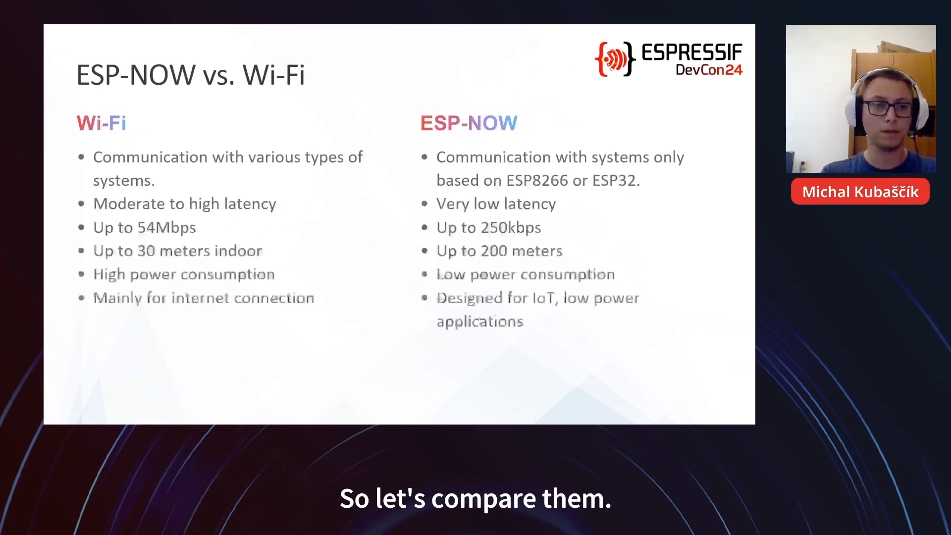
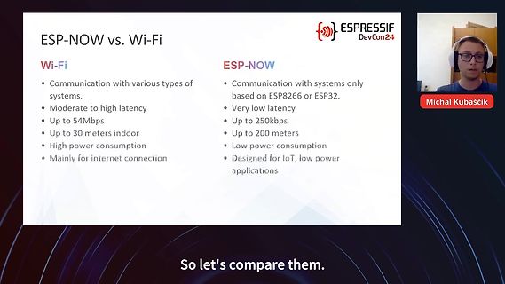
ESP -NOW vs. Wi-Fi
Wi-Fi
• Communication with various types of systems.
• Moderate to high latency
• Up to 54Mbps
• Up to 30 meters indoor
• High power consumption
• Mainly for internet connection
ESP -NOW
• Communication with systems only based on ESP 8266 or ESP 32.
• Very low latency
• Up to 250kbps
• Up to 200 meters
• Low power consumption
• Designed for IoT, low power applications
ESPRESSIF DevCon24
Michal Kubaščík
So let's compare them.
in
„Tag 3 der Espressif DevCon 2024 – von Drohne und Co“
·
Mikrocontroller und Digitale Elektronik
·
05.09.2024 23:44
·
Fotos
servonum = 0; void setup() { Serial.begin(9600); Serial.println("16 channel Servo test!"); #ifdef ESP 8266 Wire.pins(2, 14); // ESP 8266 can use any two pins, such as SDA to #2 and SCL to #14 #endif pwm.begin(); pwm.setPWMFreq(60); // Analog servos run at ~60 Hz updates yield(); } // you can use this
in
„Roboterarm mit Gestensteuerung HILFE I2C“
·
Mikrocontroller und Digitale Elektronik
·
29.12.2015 22:07
Serial.begin(115200); Serial.println("Roboterarm"); Wire.begin(0x41); Wire.onReceive(receiveEvent); #ifdef ESP 8266 Wire.pins(2, 14); // ESP 8266 can use any two pins, such as SDA to #2 and SCL to #14 #endif pwm.begin(); pwm.setPWMFreq(60); yield(); } void receiveEvent(int howMany) { if( Wire.available() ) { char
in
„Roboterarm mit Gestensteuerung HILFE I2C“
·
Mikrocontroller und Digitale Elektronik
·
30.12.2015 19:06
ABBILDUNG 1: Systemübersicht Nordic WLAN "Shockburst" 2.4 GHz \|/ \|/ | | +---------+ +-----------+ | ESP 8266 | | NRF24LE1E | +---------+ +-----------+ ^ ^ | | | +----------+ | +-----> | GD32F303 | <-----+ (B) +----------+ (C) ABBILDUNG 2: Innerer Aufbau "DTU" Nordic "Shockburst" NRF24LE1E 2.4 GHz +----
in
„Wechselrichter Hoymiles HM-xxxx 2,4 GhZ Nordic Protokoll?“
·
Mikrocontroller und Digitale Elektronik
·
16.03.2022 21:04
ABBILDUNG 1: Systemübersicht Nordic WLAN "Shockburst" 2.4 GHz \|/ \|/ | | +---------+ +-----------+ | ESP 8266 | | NRF24LE1E | +---------+ +-----------+ ^ ^ | | | +----------+ | +-----> | GD32F303 | <-----+ (B) +----------+ (C) ABBILDUNG 2: Innerer Aufbau "DTU" Nordic "Shockburst" NRF24LE1E 2.4 GHz +----
in
„Wechselrichter Hoymiles HM-xxxx 2,4 GhZ Nordic Protokoll?“
·
Mikrocontroller und Digitale Elektronik
·
16.03.2022 21:07
#include <ESP 8266 WiFi.h> #include <WiFiUdp.h> #include <TinyGPS++.h> #include <SoftwareSerial.h> // Set WiFi credentials #define WIFI_SSID "ESP 8266 " #define WIFI_PASS "12345678" // Set AP credentials #define AP_SSID
in
„NodeMCU-ESP8266-Board“
·
Mikrocontroller und Digitale Elektronik
·
24.01.2021 13:15
P$4 RC522QFN T1B 2N7002DWSOT363 GND GND 19.01.2018 11:14:52 f=0.94 C:\Users\gau2hi\Documents\eagle\ESP 8266 \esp 8266 player2.sch (Sheet: 1/1)
in
„Review Schaltung RC522“
·
HF, Funk und Felder
·
19.01.2018 11:17
// Wir laden die uns schon bekannte WiFi Bibliothek //ver 0.1 #include <ESP 8266 WiFi.h> #include <ESP 8266 WebServer.h> // Hier geben wir den WLAN Namen (SSID) und den Zugansschlüssel ein const char* ssid = "ssid"; const char* password = "pasword"; // Wir setzen den Webserver
in
„RadioButton auf einem 8266 auswerten“
·
Mikrocontroller und Digitale Elektronik
·
15.11.2020 20:57
#include <TinyGPS++.h> #include <ESP 8266 WiFi.h> #include <WiFiUdp.h> #include <SoftwareSerial.h> static const int TXPin = 4, RXPin = 5; static const uint32_t GPSBaud = 9600; unsigned int port = 2390; unsigned int port2 = 2400; long zeit1
in
„NodeMCU-ESP8266-Board“
·
Mikrocontroller und Digitale Elektronik
·
24.01.2021 13:16
..") else tmr.stop(1) print("Wifi ready, IP is "..wifi.sta.getip()) -- Send the email send_email( "ESP 8266 ", "ESP 8266 : " .. tmr.time()/60 .."min Uptime") -- never reached, deepsleep at the end of do_next() end end) -- The do_next() function is used to send the SMTP commands to the SMTP server -- in the
in
„ESP-01 Programmierung“
·
Mikrocontroller und Digitale Elektronik
·
13.04.2017 14:23
#include <ESP 8266 WiFi.h> #include <PubSubClient.h> /*--------------------------------------------*/ /* DEFAULT VALUES */ /*--------------------------------------------*/ #define WIFI_RECONNECT 5000 // Delay between
in
„SIEDLE HTA 711-0“
·
Haus & Smart Home
·
06.01.2019 14:55
#include "main.h" #include <ArduinoJson.h> #include <ESP 8266 WiFi.h> #include <pgmspace.h> #include <stdio.h> #include <String.h> #include <stdint.h> const String HFc = "2"; // Forecast = (Hfc-1) * 3h const int HFcN = 2; // Muss identisch sein mit dem String
in
„ESP8266: Mini Wetter-Station“
·
Projekte & Code
·
18.01.2019 11:58
this->_scl = _scl; } bool connect() { Wire.begin(this->_sda, this->_scl); // Let's use ~700khz if ESP 8266 is in 160Mhz mode // this will be limited to ~400khz if the ESP 8266 in 80Mhz mode. Wire.setClock(700000); return true; } void display(void) { #ifdef OLEDDISPLAY_DOUBLE_BUFFER uint8_t minBoundY =
in
„ESPEasy Sketch Kompilierungsfehler“
·
Mikrocontroller und Digitale Elektronik
·
14.12.2019 23:44
Bild
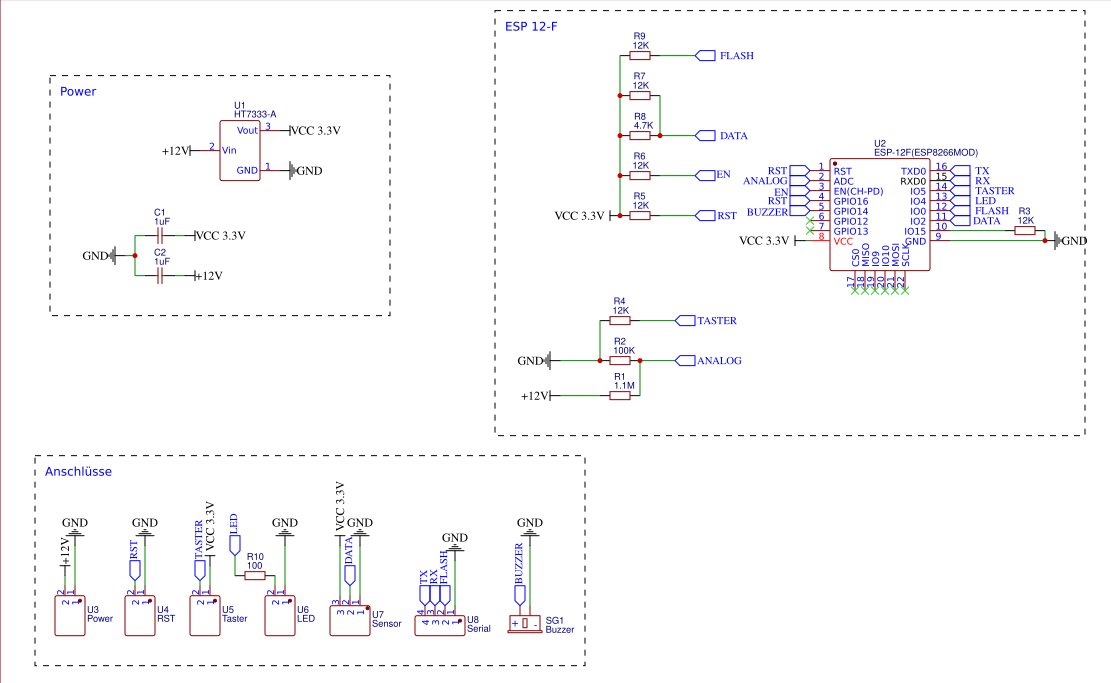
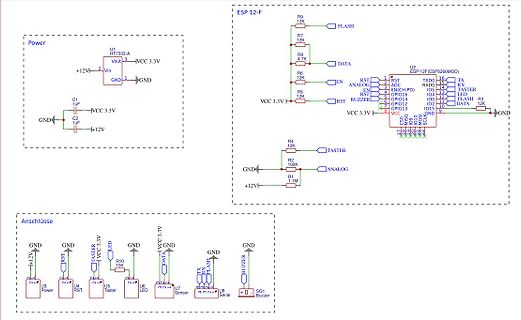
Power U1 HT7333-A Vout VCC 3.3V Vin GND C1 1uF C2 1uF GND +12V ESP 12-F R9 12K FLASH R7 12K R8 4.7K DATA R6 12K EN R5 12K ANALOG U2 ESP -12F(ESP 8266 MOD) RST GPIO16 TXD0 RXD0 TASTER IO4 LED IO0 FLASH R3 12K RST GPIO1 RST BUZZER GPIO12 IO2 GND VCC 3.3V IO15 GND R4 12K
in
„Layoutuntertstützung Platine / ESP + Tempsensor“
·
Platinen
·
10.12.2024 10:12
·
Schaltpläne
Version 1 der IO-Platine Noch ohne Netzteil, Relaiskontakte als Umschalter herausgeführt Stecker für ESP 8266 zweckentfremdet Version 1 der IO-Platine Version 2 der IO-Platine, jetzt mit Netzteil Ausgänge der Relais installationsfreundlicher: L-Klemme statt NC des Relais Version 2 der IO-Platine, jetzt
in
„Hutschienen Arduino“
·
Mikrocontroller und Digitale Elektronik
·
17.05.2017 07:53
lcd_port); // Initialize lcd // // and in the main program one updates display with // # if defined(ESP 8266 ) // ESP 8266 is special case because there is only one wire structure available // Although we can created multiple wire interfaces we still need to specify SDA and SCL // before each transmission
in
„PCF8574 I2c Adapter mit ASM ansteuern“
·
Mikrocontroller und Digitale Elektronik
·
04.08.2023 13:45
Bild
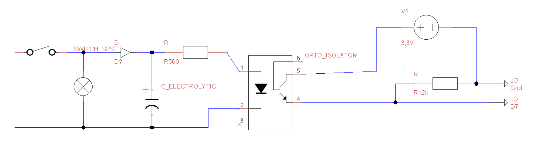
SWITCH_SPST, D, R, D?, R560, C_ELECTROLYTIC, OPTO_ISOLATOR, 6, 5, 3,3V, 1, 2, 4, R, R12k, JO Gnd, JO D7
in
„ESP-Easy mit ESP8266 - Eingang unregelmäßig falsch erkannt“
·
Mikrocontroller und Digitale Elektronik
·
19.02.2024 17:18
·
Schaltpläne
Bild
D D V D V 0 0 4 1 3 1 R M IC4A IC1C R M 1 C 1 C 1C 1 C C1DTR 13 12 9 8 R5 V C1 V C2 V V 1K0 JP3 IC1P IC2P IC3P C3 IC4P C4 JP2 74HC14D 74HC14D I2SO_DATA 1 D D D D 1 X1.1 X2.1X0_1 2 N N E N N 2 X4.1 RES_EXT RST ADC X1.2 RESET, RTS, PullUp TX0 (GPIO1) X2.2X0_3 X5.1 3 7 G 7 G 7 V 8G 7 G 3 X4.2 CH_PD X1.3 ADC RX0 (GPIO3) X2.3PIO_5 RX0_3 RX_EXT X5.2 4 4 X4.3 GPIO_16 X1.4 CH_PD GPIO5 / SCL¹ X2.4PIO_4 X5.3 5 5 X4.4 TMS_SCK_14 X1.5 GPIO16 GPIO4 / SDA¹ X2.5S1_CLK_0 X5.4 6 6 X4.5 TDI_MISO_12 X1.6 TMS² (GPIO14) boot_sel[1] (GPIO0, DTR) X2.6S0_TX1_2 X5.5 7 GND 7 X4.6 TCK_MOSI_13 X1.7 TDI² (GPIO12) TX1 (GPIO2
in
„ESP8266 Breakout, 4 x VCOM, JTAG-Debugger“
·
Mikrocontroller und Digitale Elektronik
·
17.08.2015 00:16
#include <ESP 8266 WiFi.h> #include <WiFiClient.h> #include <PubSubClient.h> #include <DHT.h> // Add your MQTT Broker IP address, example: const char* mqtt_server = "datahub.010102.de"; // Enter MQTT Server here const
in
„Monitoring Lösung / Backend für den Tüftler“
·
Offtopic
·
03.01.2021 15:10
#define Heizung 14 #define Pumpe 12 #define Ventil 13 //Blynk #define BLYNK_PRINT Serial #include <ESP 8266 WiFi.h> #include <BlynkSimpleEsp 8266 .h> char auth[] = "********"; char ssid[] = "********"; char pass[] = "********"; // Tasterabruf int Taster_Zustand; unsigned long Taster_Start; unsigned long
in
„Probleme mit Blynk und EEPROM bei ESP8266“
·
Mikrocontroller und Digitale Elektronik
·
26.10.2020 14:04
1 2 3 4 5 6 7 8 Programmer Spannungsregler Mikrocontroller - PIC16F18855 ESP 8266 +3V3 +3V3 VCC VCC VCC VCC +3V3 VCC VCC 1 IC* R1 1 ICSPDAT 2 ESP -01 10k TX 2 ICSPCLK 3 R2 VIN VOUT IC1 1 4 VCC GPIO0 6 RX 3 MCLR 4 10k 3V_SHDN C2 20 VDD RA0 2 71A 7-Segment 1 -A C R3 10k 2 CH_PD
in
„PICKIT3 - Target Halted nach Zuschaltung von Schaltregler“
·
Mikrocontroller und Digitale Elektronik
·
19.12.2017 22:13
''' CYD (Cheap Yellow Display) ESP 32 receiver showing remote BME280 values Communication Method: ESPNOW external libraries: https://github.com/rdagger/micropython-ili9341 2026-01-26 mchris ''' import network import espnow import struct
in
„Micropython Wetterstation“
·
Projekte & Code
·
26.01.2026 15:49
// #include <ESP 8266 WiFi.h> const char* ssid = "TEST"; // Setzt den Netzwerknamen, der später sichtbar ist const char* password = ""; // Setzt das Passwort, das später verwendet wird. Sollte kein Passwort gewünscht
in
„Frage zur Ansteuerung des ESP Relais“
·
Mikrocontroller und Digitale Elektronik
·
12.01.2019 19:37
/** * WLAN Monitor mit ESP -01 Modul. * * Kontrolliert die Erreichbarkeit eines Internet Servers * und zeigt den Status mit einer bunten LED an. * * Grün = Alles Ok * Blau = Verbindung ist langsam * Rot = Verbindung ist ausgefallen
in
„Quick&dirty - schnelle Problemlösungen selbst gebaut“
·
Projekte & Code
·
25.04.2017 21:48
Bild
/* web radio ESP 32 using sigma delta DAC Output: GPIO22 driver: https://github.com/earlephilhower/ESP 8266 Audio */ /* Zusammengekürzt auf das Notwendige um es selber zu verstehen... Nach dem Start wird die StreamURL
in
„Webradio basteln“
·
Mikrocontroller und Digitale Elektronik
·
13.05.2018 11:06
SW_I2C u8g2(U8G2_R0, /* clock=*/ SCL, /* data=*/ SDA, /* reset=*/ U8X8_PIN_NONE); // Adafruit Feather ESP 8266 /32u4 Boards + FeatherWing OLED //U8G2_SSD1306_128X32_UNIVISION_1_HW_I2C u8g2(U8G2_R0, /* reset=*/ U8X8_PIN_NONE); // Adafruit ESP 8266 /32u4/ARM Boards + FeatherWing OLED //U8G2_SSD1306_128X32_UNIVISION
in
„Fragen zu Waveshare e-paper 1.54"“
·
Mikrocontroller und Digitale Elektronik
·
08.01.2022 17:17
Bild
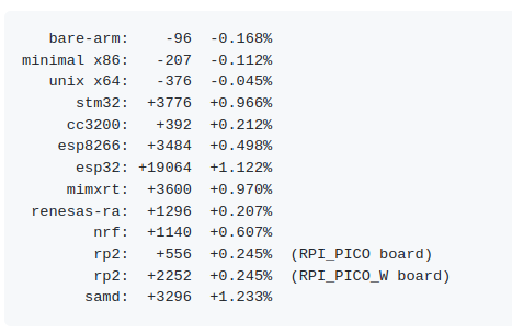
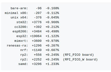
-0.168%
minimal x86: -207 -0.112%
unix x64: -376 -0.045%
stm32: +3776 +0.966%
cc3200: +392 +0.212%
esp 8266 : +3484 +0.498%
esp 32: +19064 +1.122%
mimxrt: +3600 +0.970%
renesas-ra: +1296 +0.207%
nrf: +1140 +0.607%
rp2: +556 +0.245% (RPI_PICO board)
rp2: +2252 +0.245% (RPI_PICO_W board)
samd: +3296 +1.233%
in
„MicroPython 1.26 mit I2C-Geräteemulator, Z-Wave und Matter am Vormarsch uvam“
·
Mikrocontroller und Digitale Elektronik
·
15.08.2025 00:17
·
Screenshots
Bild
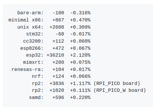
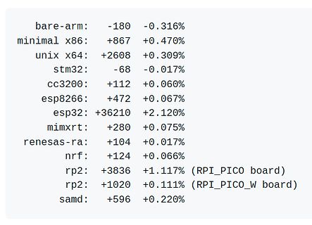
-0.316%
minimal x86: +867 +0.470%
unix x64: +2608 +0.309%
stm32: -68 -0.017%
cc3200: +112 +0.060%
esp 8266 : +472 +0.067%
esp 32: +36210 +2.120%
mimxrt: +280 +0.075%
renesas-ra: +104 +0.017%
nrf: +124 +0.066%
rp2: +3836 +1.117% (RPI_PICO board)
rp2: +1020 +0.111% (RPI_PICO_W board)
samd: +596 +0.220%
in
„MicroPython 1.27, Qt for Microcontrollers und andere Softwareupdates“
·
Mikrocontroller und Digitale Elektronik
·
18.12.2025 16:13
·
Screenshots
AN-37, P.10 VCC C13 2 IC6 100nF GND +3V GND NRF24L01+_Module 16 VCC TXD 2 TX GND 4 V3 RXD 3 RX X1 ESP _RST GND 5 GND RTS# 14 RTS# 4 13 DTR# T2 B ID 3 R14 22 5 DTR# 12 BC847C B D+ 2 R2 22 6 D+ DCD# 11 R3 DTR# D- 1 D- RI# I 10 Vbus +5V F F DSR# 9 R5 4.7k p 4 p 5 15 CTS# 47k 2 C 2 C R232 X0 8 FCI 10104111
in
„[V] ESP8266 Basisplatte mit 230V“
·
Markt
·
30.04.2019 12:13
Board • Zusammen 10€ #35 – FET Highside Switch • 2 Stück vorhanden • Von Pololu • Zusammen 6€ #36 – ESP 8266 • Diverse Module und Zubehör • Zusammen 5€ #37 – RAM • Überwiegend SO-DIMM für Notebooks • Überwiegend 1GB und 2GB Riegel • Zusammen 20€ #38 – MMR-70 FM-T ransmitter • 9 Stück vorhanden • Enthält
in
„[V] Kompletter Inhalt der Hobby-Werkstatt“
·
Markt
·
20.06.2023 11:58
Board • Zusammen 10€ #35 – FET Highside Switch • 2 Stück vorhanden • Von Pololu • Zusammen 6€ #36 – ESP 8266 • Diverse Module und Zubehör • Zusammen 5€ #37 – RAM • Überwiegend SO-DIMM für Notebooks • Überwiegend 1GB und 2GB Riegel • Zusammen 20€ #38 – MMR-70 FM-T ransmitter • 9 Stück vorhanden • Enthält
in
„[V] Kompletter Inhalt der Hobby-Werkstatt“
·
Markt
·
21.06.2023 07:59
Board • Zusammen 10€ #35 – FET Highside Switch • 2 Stück vorhanden • Von Pololu • Zusammen 6€ #36 – ESP 8266 • Diverse Module und Zubehör • Zusammen 5€ #37 – RAM • Überwiegend SO-DIMM für Notebooks • Überwiegend 1GB und 2GB Riegel • Zusammen 20€ #38 – MMR-70 FM-T ransmitter • 9 Stück vorhanden • Enthält
in
„[V] Kompletter Inhalt der Hobby-Werkstatt“
·
Markt
·
21.06.2023 13:24
Board • Zusammen 10€ #35 – FET Highside Switch • 2 Stück vorhanden • Von Pololu • Zusammen 6€ #36 – ESP 8266 • Diverse Module und Zubehör • Zusammen 5€ #37 – RAM • Überwiegend SO-DIMM für Notebooks • Überwiegend 1GB und 2GB Riegel • Zusammen 20€ #38 – MMR-70 FM-T ransmitter • 9 Stück vorhanden • Enthält
in
„[V] Kompletter Inhalt der Hobby-Werkstatt“
·
Markt
·
22.06.2023 07:41
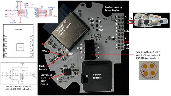
Bild
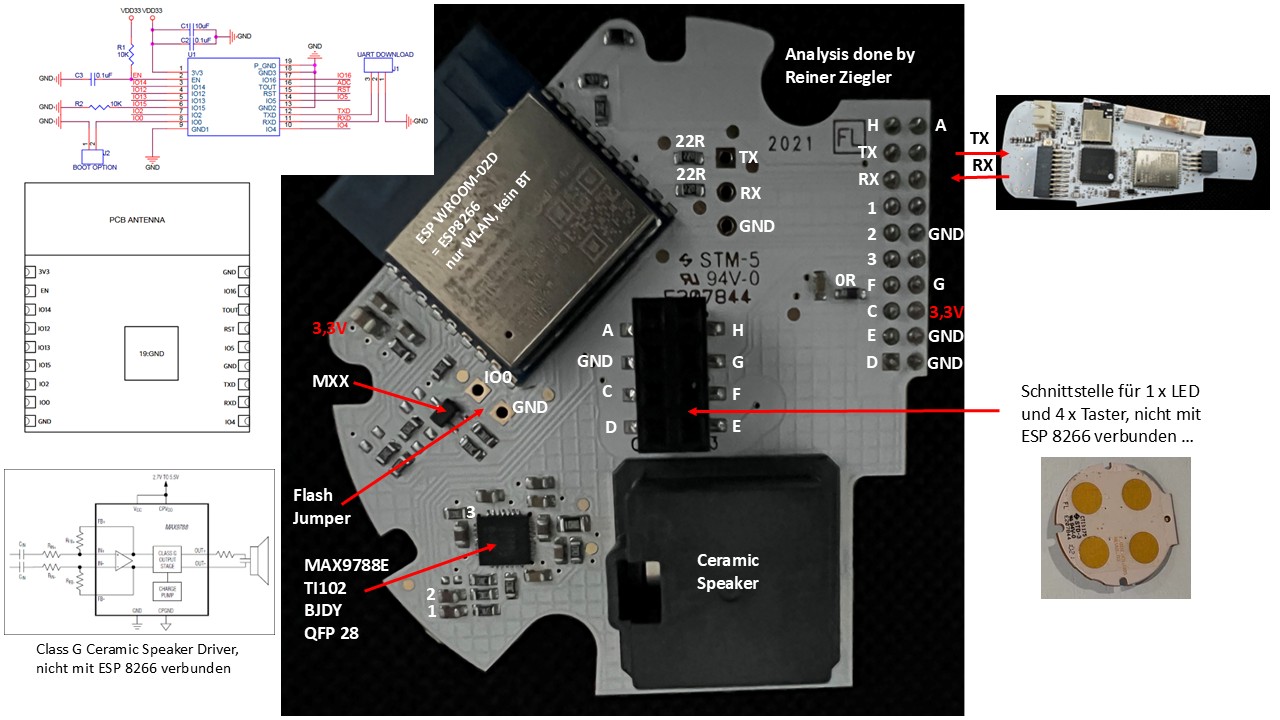
Analysis done by Reiner Ziegler ESP W:ROOM-02D = ESP 8266 nur WLAN, kein BT STM-5 94V-0 F207844 3,3V TX RX GND 1 2 3 4 5 6 7 8 G C E D A H B C D E F G H I J K L M N O P Q R S T U V W X Y Z 3,3V GND GND TX RX GND 22R 22R UART DOWNLOAD IO1
in
„erste Anlyse der Bosch Spexor Hardware“
·
Haus & Smart Home
·
31.10.2025 11:09
·
Fotos
#include <ESP 8266 WiFi.h> const char* ssid = "testserver"; const char* pass = "test4711"; const int Port = 80; IPAddress host(192,168,4,1); WiFiClient client; String req; void setup() { delay(1000); Serial.begin(9600
in
„ESP8266 Server-Client“
·
Mikrocontroller und Digitale Elektronik
·
07.12.2016 15:14
GND Version Size Page 1 Total 3 V1.0 A4 EasyEDA.com 1 ▯1 ▯2 ▯3 ▯4 ▯5 ▯6 ▯1 ▯2 ▯3 ▯4 ▯5 ▯6 SPI Memory ESP 8266 EX Chip 3V3 U4 SCS/CMD 1CS# VCC 8 GND GND SDO/SD0 2DO(IO1) HOLD# or RESET#(IO3) SHD/SD2 3V3 SWP/SD3 3WP#(IO2) CLK 6 SCK/CLK 4GND DI(IO0) SDI/SD1 ▯A 2 3 ▯A W25Q32JVSNIQ C12 X1 C13 C10 C11 18pF 40MHz
in
„ESP gesteuerter JBC T245 Lötkolben mit USB-C PD - Schematic review“
·
Mikrocontroller und Digitale Elektronik
·
08.02.2025 23:03
#include <espnow.h> #include <ESP 8266 WiFi.h> #include "ESPAsyncWebServer.h" #include "ESPAsyncTCP.h" #include <Arduino_JSON.h> // Replace with your network credentials (STATION) const char* ssid = "HD24-neu"; //FRITZ!Box 6591 Cable
in
„ESP 8266 ESP-NOW Webserver“
·
Mikrocontroller und Digitale Elektronik
·
30.06.2022 09:54
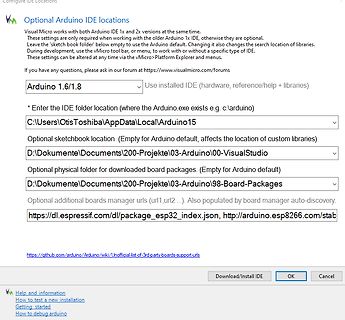
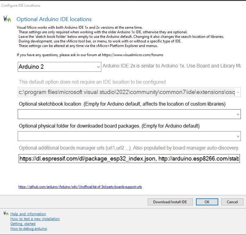
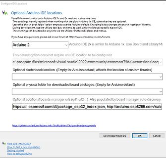
Bild
url1,url2...). Also populated by board manager auto-discovery.
https://dl.espressif.com/dl/package_esp 32_index.json, http://arduino.esp 8266 .com/stab
Download/Install IDE
OK
Cancel
Help and information
How to test a new installation
Getting started
How to debug arduino
in
„visual studio 2022 kein boardmanger zu installieren“
·
Mikrocontroller und Digitale Elektronik
·
14.02.2024 13:59
·
Screenshots
/*-------------------------------------------------- v1.0 MSoft 14.05.2016 ESP -01 - 1MBit-Flash Mno SPIFFS), QIO --------------------------------------------------*/ #include <ESP 8266 WiFi.h> #include <ArduinoOTA.h> #include <Ticker.h> #include <AsyncMqttClient.h> //#define DEBUG
in
„ESP Frage zu Setup-Code, mit reconnect, etc.“
·
Mikrocontroller und Digitale Elektronik
·
30.11.2019 09:59
/*-------------------------------------------------- v1.0 MSoft 14.05.2016 ESP -12 - 1MBit-Flash: 1Mno SPIFFS), QIO --------------------------------------------------*/ #include <ESP 8266 WiFi.h> #include <ArduinoOTA.h> #include <Ticker.h> #include <AsyncMqttClient.h> //#define DEBUG
in
„ESP8266 crash während updateWifi() - ist millis() das Problem?“
·
Mikrocontroller und Digitale Elektronik
·
30.09.2018 21:10
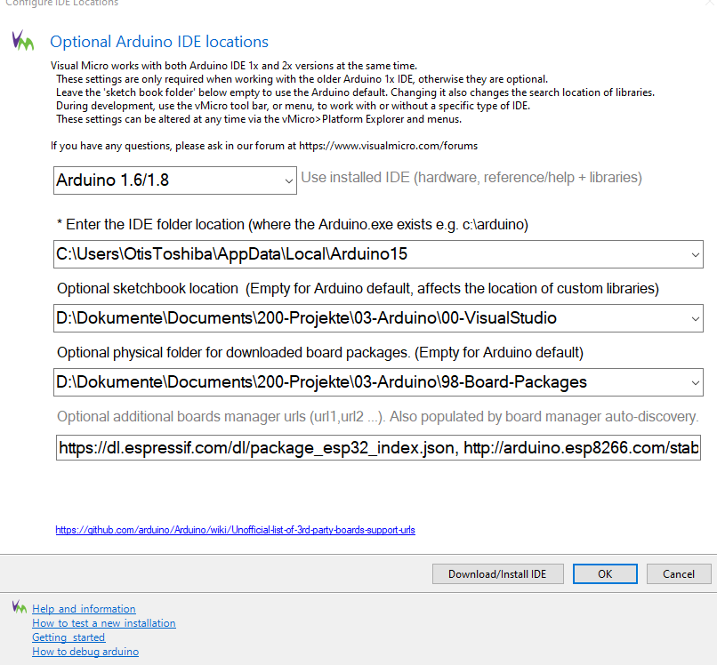
Bild
url1, url2 ...). Also populated by board manager auto-discovery.
https://dl.espressif.com/dl/package_esp 32_index.json, http://arduino.esp 8266 .com/stab
https://github.com/arduino/Arduino/wiki/Unofficial-list-of-3rd-party-boards-support-urls
Download/Install IDE
OK
Cancel
Help and information
How to test
in
„visual studio 2022 kein boardmanger zu installieren“
·
Mikrocontroller und Digitale Elektronik
·
14.02.2024 13:59
·
Screenshots
#include <Arduino.h> #include <pcf8574_esp .h> #include <PolledTimeout.h> #define PCF_INT_PIN D5 #define PCF_DEBOUNCE_MS 50 #define PCF_INPUT1 3 #define PCF_INPUT2 2 #define PCF_INPUT3 1 #define PCF_INPUT4 0 PCF857x pcf8574(0x20, &Wire); esp 8266
in
„ESP8266 mit PCF8574 und Taster - Interrupt vom PCF "spinnt"?“
·
Mikrocontroller und Digitale Elektronik
·
17.04.2020 10:19
#include <Arduino.h> #include <pcf8574_esp .h> #include <PolledTimeout.h> #define PCF_INT_PIN D5 #define PCF_DEBOUNCE_MS 50 #define PCF_INPUT1 3 #define PCF_INPUT2 2 #define PCF_INPUT3 1 #define PCF_INPUT4 0 PCF857x pcf8574(0x20, &Wire); esp 8266
in
„ESP8266 mit PCF8574 und Taster - Interrupt vom PCF "spinnt"?“
·
Mikrocontroller und Digitale Elektronik
·
17.04.2020 15:54
UNIVISION_SW_I2C u8x8(/* clock=*/ SCL, /* data=*/ SDA, /* reset=*/ U8X8_PIN_NONE); // Adafruit Feather ESP 8266 /32u4 Boards + FeatherWing OLED //U8X8_SSD1306_128X32_UNIVISION_SW_I2C u8x8(/* clock=*/ 21, /* data=*/ 20, /* reset=*/ U8X8_PIN_NONE); // Adafruit Feather M0 Basic Proto + FeatherWing OLED //U8X8_SSD1306_128X32_UNIVISION_HW_I2C u8x8(/* reset=*/ U8X8_PIN_NONE); // Adafruit ESP 8266 /32u4/ARM Boards + FeatherWing OLED //U8X8_SSD1306_128X32_UNIVISION_HW_I2C u8x8(/* reset=*/ U8X8_PIN_NONE, /* clock=*/ SCL, /* data=*/ SDA); // pin remapping with ESP 8266 HW I2C //U8X8_SSD1306_128X32
in
„Mini Display ansteuern“
·
Mikrocontroller und Digitale Elektronik
·
25.07.2023 14:41
/* Hardware setup for this Fuellstandmesser: 5110 LCD <--->ESP 8266 Vcc -- 3.3V GND -- GND SCE -- 15(D8) RST -- 0(D3) D/C -- 2(D4) Mosi -- 13(D7) Sclk -- 14(D5) LED -- 1k Ohm -- 3.3V VL53LXx Vin -- 3.3V GND -- GND SCL -- 5(D1) SDA -- 4(D2) by snowfly */ /** IotWebConf06MqttApp.ino -- IotWebConf is an ESP 8266 /ESP 32 non blocking WiFi/AP web configuration library for Arduino. https://github.com/prampec/IotWebConf Copyright (C) 2018 Balazs Kelemen <prampec+arduino@gmail.com> This software may be modified
in
„Der letzte Füllstandmesser“
·
Projekte & Code
·
10.06.2019 10:09
SWITCH_ALARMSTATUS A MIC521G-3.3YM5 2 ADC GPIO4 19 A þÿ4,7µF U2 20 CH_A2 REL1 2 100nF GPIO5 CH_GND GNDD 9 CS0 ESP -12E GPIO12 6 CH_GND GNDD CH_C5 10 7 CH_ALARM_BREAKE_A CH_D1D4D4 ALARMFROMESP 470nF MISO GPIO13 SWITCH_ALARMSTATUS Barrel_Jack_Switch 11 5 CH_A1D6 ALARM_CAM_DI GPIO9 GPIO14 ALARMFROMESP 1 CH_12V 12 GPIO10
in
„Zeigt her eure Kunstwerke (ab 2023)“
·
Projekte & Code
·
22.04.2026 21:52
PCF8574 { public: explicit PCF8574(const uint8_t deviceAddress, TwoWire *wire = &Wire); #if defined (ESP 8266 ) || defined(ESP 32) bool begin(uint8_t sda, uint8_t scl, uint8_t val = PCF8574_INITIAL_VALUE); #endif bool begin(uint8_t val = PCF8574_INITIAL_VALUE); bool isConnected(); uint8_t read8(); uint8_t
in
„Fehler bei PCF8574.h Bibliotheke“
·
Mikrocontroller und Digitale Elektronik
·
16.04.2021 20:17

 Bild
Bild
 Bild
Bild
 Bild
Bild

 Bild
Bild
 Bild
Bild
 Bild
Bild
 Bild
Bild
 Bild
Bild
 Bild
Bild
 Bild
Bild