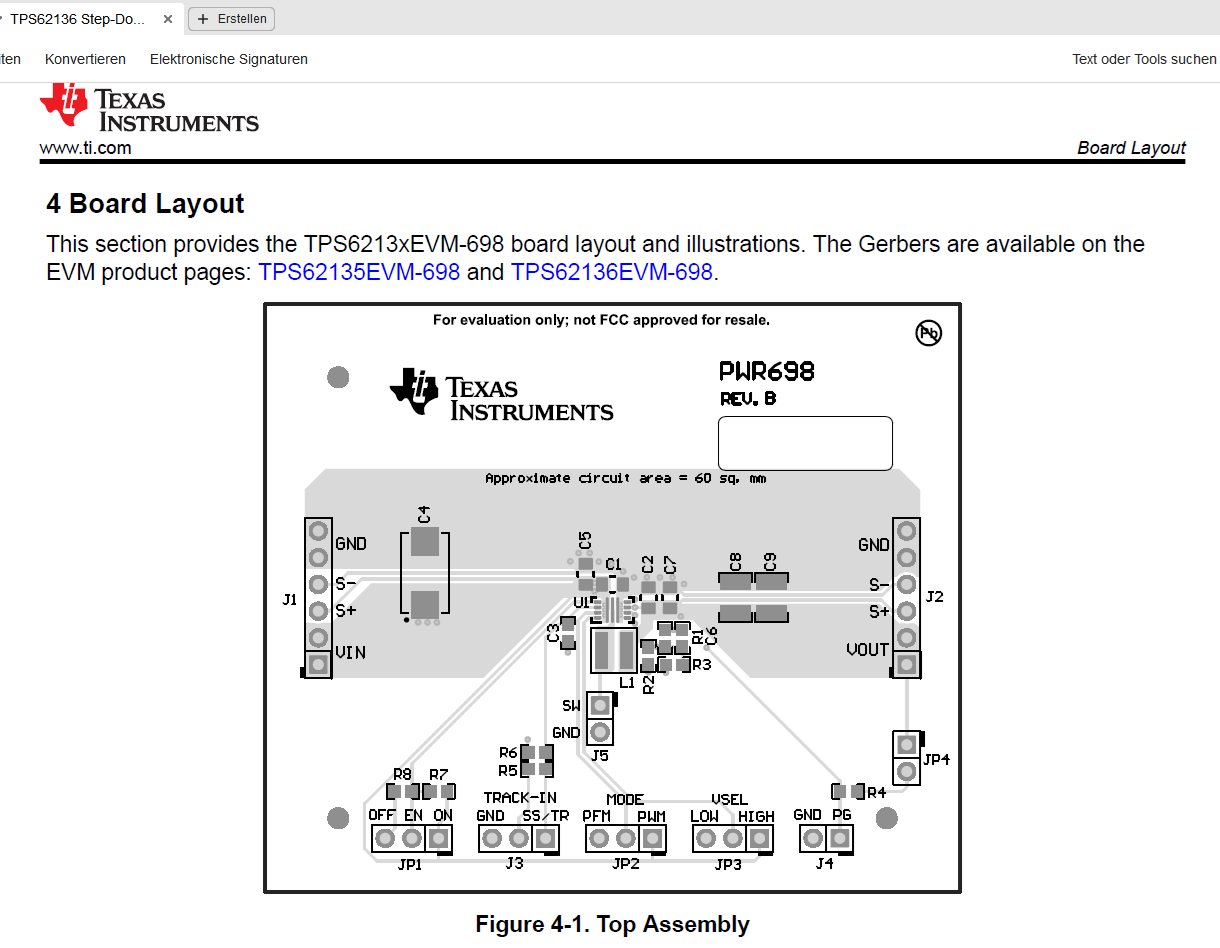
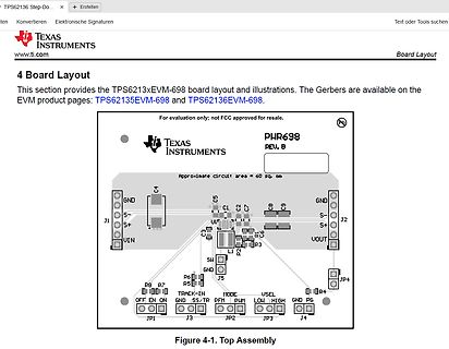
Specification Test Conditions MIN TYP MAX Unit Input voltage 3 17 V Output voltage setpoint VSEL = High 5 V VSEL = Low 3.3 V Output current 0 4 A 1.2 Modifications The printed-circuit board (PCB) for this EVM is designed to accommodate the adjustable voltage version of this integrated circuit (IC). On
FTR-K1 SERIES POWER RELAY 2 POLES - 5A LOW PROFILE TYPE FTR-F1 Series n FEATURES l Low profile (height: 16.5mm) l DPST/DPDT 5A, TV-3 rating available l High insulation (due to its reinforced insulation construction) Insulation Distance (between
https://ww1.microchip.com/downloads/aemDocuments/documents/APID/ProductDocuments/DataSheets/MIC5236-Low-Quiescent-Current-%C2%B5Cap-LDO-Regulator-20006574B.pdf 27k und 16k am ADJ-Pin ergibt 3.3 Volt und wegen aggressiver Stücklisten-Optimierung gibt es auch keine 1N4007 und keinen Schaltregler mit
Der MIC5236 wird durch einen ohne Enable ersetzt und ein anderer Spannungsregler wird durch einen High Side Switch ersetzt. Dann vertragen alle ICs am Akku -20 Volt, nur die OPs und ein MUX werden durch die Diode geschützt.
copper conductor integrated into the package making it Single 5V Supply Operation suitable for both high-side and low side bi-directional current Low power consumption (6.5mA typical) sensing. The high bandwidth of 1.5MHz (3dB) and low Zero-Current Reference Pin (Vref) phase delay makes it ideal for
Andrew T. schrieb im Beitrag #8040282: > Zu wenig Infos. > z.B. gewünschte Bandbreite, Höhe des high side Spannung, etc.
störungsfrei funktioniert, warum könnte man die > nicht einfach überall einsetzen? Warum nicht auch an der Low-Side? Low Side müsste die ja gar nicht Potentialfrei sein. Das Thema hatten wir schon, dass Messung sehr kleiner Ströme auf Low Side absolutes No-Go sind.
Reise > schicken und an der Empfangsseite ein 1kΩ Widerstand gegen Masse liegt, > dann wird der High-Pegel nur um ca. 3% gesenkt. Und die Serienterminierung wird zum Glück auch nur um 3% verfehlt. > Gleichzeitig geistert aber nicht jeder aufgefangene Störimpuls in > die ›Din‹ der ersten LED. Warum sollte ohne diesen 1k Widerstand irgendwas geistern können? Denn es werden ja beide Pegel (High und Low) niederimpedant aktiv getrieben. > Und bei gerade mal 800kHz sieht das Signal auch bei 12m noch prima aus. Wenn du die Signalform gemessen hast, dann passt das ja.
internal clock sources can be used as a reference to the internal PLL in order to generate even higher frequencies. The PLL is covered in the High-frequency PLL Option section. Ultra-low Power 32kHz RC Oscillator The Ultra-low Power 32kHz internal RC oscillator (ULP32K) is mainly used for system purposes
or of the external signal connected to EXT IN is too low for the frequency 8 Error of the programmable electronic counter. circuit tEMP. The generator is switched off due to overtemperature. Remark on error "1" and error "4" These errors cannot be removed
thermistors PTC resistance R PTC versus versus applied voltage (pulsed) PTC temperature T PTC (measured at low signal voltage) Switching time t Sersus switching current I S Residual current in high-ohmic state I resas (measured at 25 °C in still air) function of applied voltage V , typical PTC (measured at 25
Logikausgang, der die Hüllkurve der Amplitudenmodulation ausgibt. Die Sekundenpulse sind dann aktiv high oder low. Du kannst Dein Modul austauschen wenn die Betriebsspannung passt, also 1,8, 3,3 oder 5 V, und wenn die Polarität des Ausgangs passt.
LEDPIN, OUTPUT); } void loop() { // put your main code here, to run repeatedly: digitalWrite(LEDPIN,LOW); delay(1000); digitalWrite(LEDPIN,HIGH); delay(1000); }
läuft erst ab 8V, bevorzugt mit 12V, also sollte ein normaler MOSFET wie SUP60030E kein Problem sein, high side wird über high side Treiber angesteuert.
SUP60030E kein > Problem sein, Da wird man noch mehr finden, evtl sogar noch besser geeignete. > high side wird über high side Treiber angesteuert. Es gibt nur zwei Low-Side.
is activated every six oscillator periods except during external data memory access. PSEN remains high during internal program e x e c u t i o n . E A When held at a TIL high level, the 8051AH executes instructions from the i n t e r n a l Rw h e n t h PC is less t h a n 4096. W h e nheld at a TTL~-low
2O04 93]f03[3]CP PINNING D HEF 401748 DotoDs datainputs 7 MR Og Do Dy 0; -D2 O02 Vss5 _ _ clockinput (LOW toHIGH edgetriggered) : [6] 8] MR masterresetinput(activeLOW) Pinningdiagram OotoOg bufferedoutputs F U N C T I O N T A B L E lcelo [im | o J |H H H J L H L : L I X H no change X |X PL L i, H = HIGH
, IFC Also after ATN, the microcomputer reads the selected device address by making pin 10 of D605 low and input 19 of D604 high (high impedance). Then themicrocomputer startshandshaking thedeviceaddresson the bus. This iscontrolled viaP1 of the microcomputer. Ifthe device address on the bus isthe same
2i2 4th Generation # https://www.thomann.de/de/focusrite_scarlett_2i2_4th_generation.htm c) High-End - MOTU M2 # https://www.thomann.de/de/motu_m2.htm # https://motu.com/en-us/products/m-series/m2/ // Davon nutze ich selber das a) das Behringer UMC404HD mit 4x XLR Mic Eingängen für Podcasts
heute in meiner Wohnung aufgebaut: a) AKG C 1000 S MKIV mit 2x 1,5 V neuen Bat, 0 dB (Pad) und LowPass Filter aktiv. Mit standart Nieren Charakteristik b) Triton Audio FetHead - direkt am AKG C 1000 S angeschlossen c) König & Meyer 260/1 Mikrofonstativ mit the t.bone SSM 6 Spinne - zur Aufstellung
über I2C-Adresse und nicht per erstem übertragenen Byte, wie übliche Konvention * OQ0070 verträgt low-gezogenes SCL-Signal # Doku OQ0070-select-Trick * Start-condition: SDA fallende Flanke, während SCL high. * Stop-condition: SDA steigende Flane, während SCL high. * Select-Umschaltung: während SDA high, ändert SCL den Pegel. OQ0070 erkennen keine conditions. mfg mf
also have to * * consider the automatic use of the new units by system- level design tools, such as high-level language to hardware compilers [1]. In general, realizing all required multiply-add e f g + (MA) operations by very fast (low latency, high throughput) * * implementations is not efficient, as
k+1:n▯1;k:n▯1 ▯ 2v kv k k+1:n▯1;k:n▯1 ); /*Step 2 /* Virtex 5 show that both architectures have higher frequency 1.4 A 0:n▯1;k+1:n▯1 = and lower latency than all previous work. A 0:n▯1;k+1:n▯1 ▯ 2(A 0:n▯1;k+1:n▯1 k )v ▯; /*Step 3 /* k R EFERENCES [1] G. Lienhart, A. Kugel, and R. Manner, “Using floating-point
of adders to be used and the delay that our heavily pipelined (48 stages) FAAC design can obtain high clock frequencies (and subsequently high performance) of the whole accumulator. Figure 3 shows the two cases for k = 4 and k = 8. Notice that the number of adders is not while using a relatively small
at column inputs are transferred to the column drivers on the rising edge of each clock pulse. A high column input causes the LED to turn on. After the minimum hold time requirement has been satisfied, the column data inputs may change whether the clock is high or low. (1) 2 (16) (2) 3 ROW 4 (15) ANODES
nun ein update. Zur Info: Beim Motorcontroller handelt es sich um einen BLDC, es würde also drei high side Gatetreiber geben und drei low side. Ich hoffe, dass Diode1 den Spitzenstrom beim Aufladen des Elkos verträgt, habe den niederohmigen Widerstand beim Elko entfernt.
ja einfach hochohmiger und damit langsamer machen und eine entsprechende Totzeit beim Übergang von high-low-high programmieren. Im Anhang ein Vorschlag mit viel höherer Geschwindigkeit (~40ns Verzug, Schaltfrequenz jetzt 1MHz) und viel weniger Strom bzw. Verlustleistung. Die Schaltung kann man direkt
in Figure 4-30. In this measurement, an LED operated in a double-pulsed mode is used to provide higher and lower pulse amplitudes alternately. The higher and lower pulse amplitudes are fixed at a ratio of approximately 4:1. If the photomultiplier tube outputs in response to the higher and lower pulsed
computer and/or display, after a certain period of inactivity, shall reduce its power consumption to a lower level in one or more stages. The length of time to reactivate the computer shall be reasonable for the user. Labelled products must meet strict environmental demands, for example, in respect of the
Problem, dass er bei der Datenausgabe die Werte verschoben ausgibt.Es sollten für jede Achse 2 Bytes ( 1.Low /2.High) ausgegeben werden, d.h. xL-Achse = axis(0), xH =axis(1), yL = axis(2) usw. bis zH = axis(5) Tatsächlich wird aber xL =axis(1), xH =axis(2)...zH =axis(0) ausgegeben. Bei Spektrum Analyser
the power transistors and t window 2.60 μs−3.60 μs 1.90 μs−2.30 μs si the magnetic circuit leads to high voltage spikes that make Drive High & Low side Low side only this topology difficult to use for line voltage above 120 V. Intrinsic Galvanic no yes Isolation Additionally, it is not practical to dim
Push-Pull**-Ausgang ist (nötig für LEDs). 4. **`HAL_GPIO_TogglePin()`**: Schaltet den Pin zwischen High und Low. 5. **`HAL_Delay()`**: Das Standard-HAL-Verzögerungsbasiert auf dem Systick. `HAL_Delay(500)` wartet 500 Millisekunden. ### Empfehlung Da die Initialisierung (Clocks, Pins, Interrupts) bei den
protection and energy saving, high brightness, scattering angle is large, good consistency, low power, long life and other advantages. The control chip integrated in LED above becoming more simple circuit, small volume, convenient installation
, , 1 a 0 m ø , 2 1,0 All dimensions in mm typical APPLICATIONS DESCRIPTION IoT The MS1V-T1K is a low frequency surface mount technology Quartz Metering Crystal Unit that incorporates a tuning fork Quartz Crystal Resonator. It Wearables operates under vacuum in a hermetically sealed square-bodied metal Health Care can package. Consumer Electronics FEATURES High stability is guaranteed by hermetic sealing. High shock and vibration resistant. Proven surface mount technology package for reflow soldering. Excellent lead coplanarity for surface mounting. RoHS-compliant
than 4 diodes, and a rectification controller IC for use with an external FET, suitable for either high-side or low-side rectification. The RVS002 integrates two N-channel MOSFETs and two Schottky diodes in a DFN2*2 package to create a low-loss full bridge rectifier capable of handling up to 3W.
conversion applications. The rectification IC is self-powered from a single AC input allowing either high side or low side rectification. The controller supports both CCM and DCM operation and is compatible with both QR and active clamp flyback topologies. . . . The RVPWxxx series flyback power ICs
davorsetzt, dann wird es spannend. Denn wenn du den LED-Streifen mit 5V betreibst, reicht auch das High-Setzen des Din-Pins nicht mehr aus, weil 5V-3,3V mehr als die erlaubten 0,5V ergibt.
Danke Lothar. > Aber das müsste dann Softwaretechnisch gelöst werden? > Oder per Hardware? Higher als high geht nicht - auch nicht per Software. Du brauchst einen Pegewandler, der damit klar kommt. Oder einen herkömmlichen ein/aus Schalter, und den Transistor weglassen. Dann entfällt auch die Strombegrenzung
der speziell für Hi-Fi-Anwendungen entwickelt wurde. Er ist bekannt für seine geringen Verzerrungen (low distortion) und das niedrige Rauschen, was ihn zu einer beliebten Wahl für hochwertige Audioverstärker macht. -------------------------- Linearität bei niedrigen Frequenzen: Der TA2024 (speziell
z.b. mit Programmen wie REW mal einen LS oder Chassis zu messen. Ich habe keinen Anspruch auf High End oder Profi Level. https://www.roomeqwizard.com/ Bisher war es dieser kleine Kerl: https://www.amazon.de/Dayton-Audio-DTA-1-Battery-Amplifier/dp/B001PNOH2I Bzw. dessen Vorgänger, der
415wp-pv-modul-blackwhite-monokristallin.html Die Preise, die deutsche Hinterhof-Zubehörlieferer für ihren lowest tech Scheiss verlangen sind aberwitzig gegenüber dem was man für das Geld aus China für high tech bekommt. 4 Gehwegplatten, 4 Blechwinkel, 1m Aluprofil und ein paar Schrauben ist alles was man zum
415wp-pv-modul-blackwhite-monokristallin.html > > Die Preise, die deutsche Hinterhof-Zubehörlieferer für ihren lowest tech > Scheiss verlangen sind aberwitzig gegenüber dem was man für das Geld aus > China für high tech bekommt. > > 4 Gehwegplatten, 4 Blechwinkel, 1m Aluprofil und ein paar Schrauben ist >
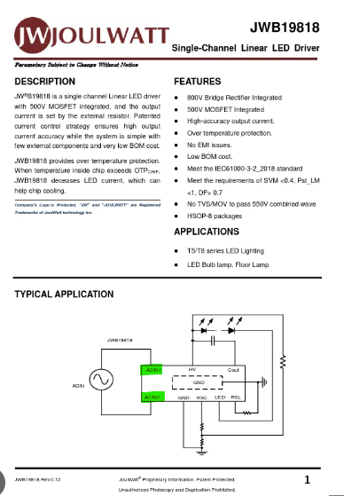
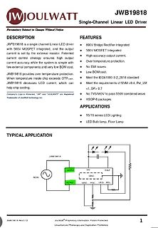
Subject to Change Without Notice FEATURES 800V Bridge Rectifier Integrated 500V MOSFET Integrated High-accuracy output current. Over temperature protection. No EMI issues. Low BOM cost. Meet the IEC61000-3-2_2018 standard Meet the requirements of SVM <0.4, Pst_LM > 0.7 APPLICATIONS T5/T8 series LED Lighting
#8035020: > Dafür kannst du die zur Not auch mit Kabel nach draußen legen. Das ist sicherlich, wenn Low-ESR gefordert ist, der ... "beste" Weg, genau das nicht zu erreichen.
Thomas S. schrieb im Beitrag #8047519: > Ich brauche keinen High-Turbo-super-tupper !! Das hat jeder kapiert, und auch, daß du mit einem schnarchlangsamer Rechner mehr als zufrieden bist. Das macht ja auch nix. Nur wird dadurch das Gerät trotzdem keine Rakete,
machen lassen will. Grundsätzliche Funktionen der Schaltung: - RPi ist aus (+3.3V Rail am RPi ist LOW, GPIO Ausgang ist LOW): Nach dem drücken des Tasters oder IR Fernbedienung fährt der RPi hoch (+3.3V Rail am RPi ist HIGH). Die Led blendet(fadet) hoch und runter bis ein Python Skript den GPIO Ausgang
nach Bedarf hoch oder > runterziehen. Es geht nicht darum, dass man die Portpins als Ausgang high oder low schalten kann, sondern ob man an einem Eingangs-Portpin einen Pullup zuschalten kann.
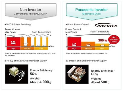
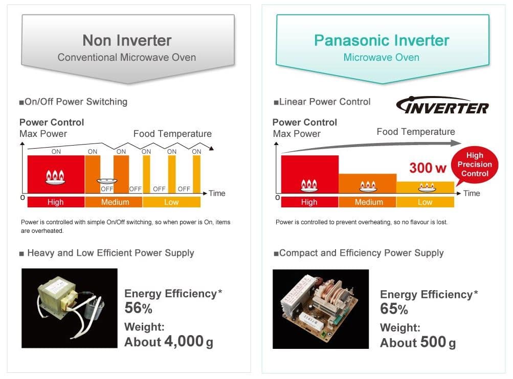
Microwave Oven
On/Off Power Switching
Power Control Max Power
Food Temperature
ON ON ON
OFF OFF OFF
High Medium Low
Time
Heavy and Low Efficient Power Supply
Energy Efficiency* 56%
Weight: About 4,000 g
Panasonic Inverter Microwave Oven
Linear Power Control
Power Control Max Power
Food Temperature
High
the „ESC Y W“ command. A maximumcurrentof10mAcanbeswitchedperline.Thisgivetheopportunity to drive a low power LED in direct way. To source higher current please use an external transistor. EXTENDEDOUTPUTS It is possible to connect 1 to 32 chips like 74HC4094 to the eDIP (OUT1...OUT3), this is why it is

 Bild
Bild
 Bild
Bild
 Bild
Bild