family of equations, Eqs. 2.5-3, shows that each contains a current or a voltage on the right-hand side. However, that parameter is defined in the next equation above. A continued substitution will eventually terminate at the input voltage which was defined.The result is (2.5-4) This method appears formidable
may have a vast range, depending on the used MOS-FET, e.g. down to 2 Volt at the “Lower voltage” side and up to 10 Volt or more at the “Higher voltage” side of the level shifter. An additional function of the level shifter is that it can isolate a powered-down section in a bus system, without obstructing
Bedienelemente usw. für alte Technik sucht... https://forum.zerspanungsbude.net/viewtopic.php?f=16&t=87577&sid=dc8b859c439ddefdc43b98cf005b4d22 Grüße Bernd
Client to initiate a transaction, A MODBUS Indication is the Request message received on the Server side, A MODBUS Response is the Response message sent by the Server, A MODBUS Confirmation is the Response Message received on the Client side The MODBUS messaging services (Client / Server Model) are used
panel or a PC, which implements an RS232 Data Terminal Equipment. ITr Physical bus Interface on Trunk side. IDv Physical bus Interface on Derivation (or tap or device drop) side. LT Line Termination. MODBUS Device a Device that implements MODBUS over Serial Line and respects this Technical Note. RS232 EIA
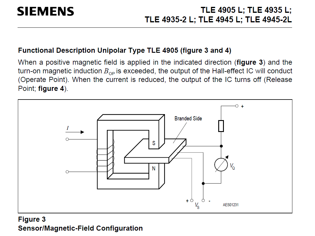
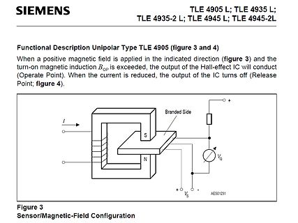
). When the current is reduced, the output of the IC turns off (Release Point; figure 4).
Branded Side
S
N
+
+
-
VO
VS
AES01231
Figure 3
Sensor/Magnetic-Field Configuration
ich zudem in jedem Mux Zyklus eben schnell eine Zeile Tasten abchecke bevor ich die nächste High-Side der "Spalte" aktiviere...augenscheinlich ist es wohl so geplant dass man ein Bit auf dem 8-Bit Bus durchlaufen lässt und dann jeweils bei Pin 13 (T1) schaut ob die Taste gedrückt ist...
insured with isolated interconnections. a second PIN photodiode (pins 5, 6) located on the output side These isolated interconnections commonly use isolation ampli- of the coupler.The output current, IP2, from this photodiode fiers. accurately tracks the photocurrent generated by the servo pho- todiode
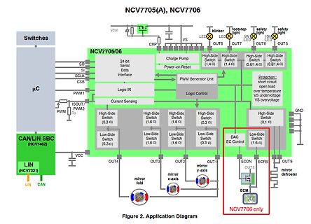
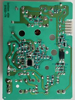
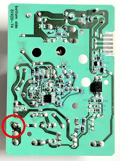
Da wird wohl der High-Side-Schalter durchlegiert sein. Das Modul scheint man ja öffnen zu können, evtl lässt sich der defekte Chip austauschen.
H. H. schrieb im Beitrag #7940138: > Da wird wohl der High-Side-Schalter durchlegiert sein. Das Modul scheint > man ja öffnen zu können, evtl lässt sich der defekte Chip austauschen. Wenn das so wäre, ist den der Effekt das der Schalter eine Masseverbindung
, sogar auf Ausnutzung von Bugs des SID > (Sounderzeugung durch Änderungen des Lautstärke-Registers). Mit SIDs kann man schon interessante Klänge erzeugen. Je mehr* SIDs, umso beeindruckender das Ergebnis. Es können auch /emulierte
. Der Hüllkurvenformer (aka ADSR+VCA) ist ein Added-Bonus. Genauso der VCF. Die emulierten SIDs sind nichts anderes als /gesamplete/ SIDs (PAL/NTSC/SID-Derivate) und einer GigaSampler-Engine unten drunter. Als Einzelstimme ist gegenüber einem SID auch /kein/ Unterschied auszumachen. Sie ist
AND DIMENSIONS APPLY SOLDER MASK TO AREAS THAT ARE NOT SOLDERED 4.00 ±0.10 R = 0.115 0.40 ± 0.10 (2 SIDES) TYP 7 12 R = 0.05 TYP 3.30 ±0.10 3.00 ±0.10 PIN 1 (2 SIDES) 1.70 ± 0.10 TOP MARK PIN 1 NOTCH (NOTE 6) R = 0.20 OR 0.35 × 45° (UE12/DE12) DFN 0806 REV D 6 1 0.200 REF 0.75 ±0.05 0.25 ± 0.05 0.50 BSC
operation. The weight of the sensor is approx. 0.6 g. Figure 3: Sensor package dimensions of SCD4x: top, side and bottom view (left to right, projection method 1). All dimensions in millimeters. 4.2 Land Pattern Recommendation Recommended land pattern, solder paste, and solder mask are shown in Figure 4. The
single-ended amplifier configura- In order to reduce power consumption while not in use, the tion where one side of its load is connected to ground. LM9022 contains a shutdown pin to externally turn off the A bridge amplifier design has a few distinct advantages over amplifier’s bias circuitry. This shutdown feature
peak-detection genutzt habe fehlt aus Lizenzgründen. Kannst du aber mit browserify in ein browser-side slayer.js umwandeln wie ich es gemacht habe). Das kannst du dann mit allen chrome basierten browser (Chrome, Chromium, Edge, Brave, ...) öffnen (musst eigentlich nur das index.html im browser öffnen
Proceeding: REAR MOLD PANEL (1) Remove the screws. ↑Shooting direction: A↑ View from the bottom 15 2. SIDE PANEL Proceeding: REAR MOLD PANEL → SIDE PANEL (1) Remove the screws. Front side STEP1 STEP1 STEP2 STEP2 TOP SIDE TOP SIDE View from the bottom 3. TOP PANEL ASSY Proceeding: REAR MOLD PANEL → SIDE PANEL
installing a battery in a device, make sure that the positive terminal is facing up, or at least to the side. As this battery uses Battery Battery liquid thionyl chloride as the positive active material, placing the positive terminal at the bottom will cause the thionyl chloride to become maldistributed, which
defined, C programs can use names like <tt>PORTA</tt> directly in C expressions (also on the left side of assignment operators) and GCC will do the right thing (use short I/O instructions if possible). The \c __SFR_OFFSET definition is not used in any way in this case. Define \c _SFR_ASM_COMPAT as 1
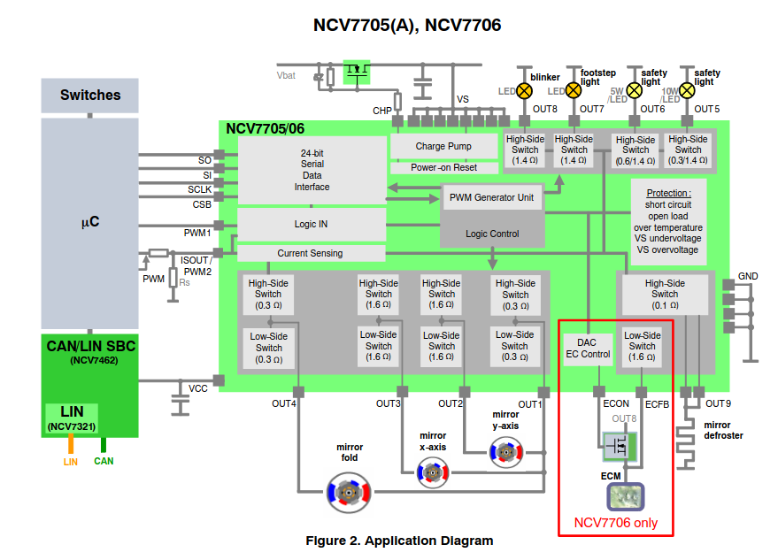
der zu erwarten ist. Bei Einspritzungen ohne den falschen Peak fällt die Spannung auf der Low-Side Leitung e-förmig ab wie zu erwarten. Gemessen hab ich beide Leitungen gegen Masse und dann im Oszilloskop Low-Side von High-Side abgezogen. Strom mit Stromtastkopf. Gemessen hab ich bei Leerlauf
Bilder angehängt. Einmal Spannung mit regulärem Verlauf, einmal Spannung mit Peak. Blau ist High-Side, Rot Low Side, Violett die Differenz und damit die am injektor anliegende Spannung, sowie Grün der Strom durch den Injektor. Darüber hinaus sind nochmal die Ströme einzeln aufgezeichnet. Die Frage
hier z.B einen doppelten Switch: https://www.reichelt.de/de/de/shop/produkt/power_switch_high_side_usb_active_low_so-8-386821 Keine Ahnung ob die auch einen einzelnen haben. Musst du halt selber mal suchen. Vanye
nennt sie Load > switch. In Zeiten der Halbleiterkrise mußte ich leider merken, daß bei High-Side Treibern jeder Hersteller sein eigenes Süppchen kocht, bezüglich Verhalten, Pinbelegung und Footprint. Es gibt keinen Standard. Ich bin daher wieder auf einzelne MOSFETs zurück. SOT-23 bleibt eben
firm. ● When climbing up the ladder, keep your body stable and your center of gravity between the side rails, and do not overreach to the sides. ● When a step ladder is used, ensure that the pull ropes are secured. ● If a single ladder is used, the recommended angle for the ladder against the floor is
FIPS PUB 197/180/180-2/180-4 and NIST SP 800-38A, as well as a hardware key store to protect against side-channel and fault injection attacks. In terms of secure boot mechanism, the upgraded M2354 supports the Root of Trust architecture based on DICE, implemented in Mask ROM, and supports ECDSA P-521. This
value increment is 35ps. If you use XO2 devices, you can instantiate either a “DELAYE” element (all sides) in the HDL to add a user-specified amount of delay, or a “DELAYD” element (bottom side) in the HDL to add a dynamic delay. For example: component DELAYE generic(DEL_MODE: in String; DEL_VALUE: in
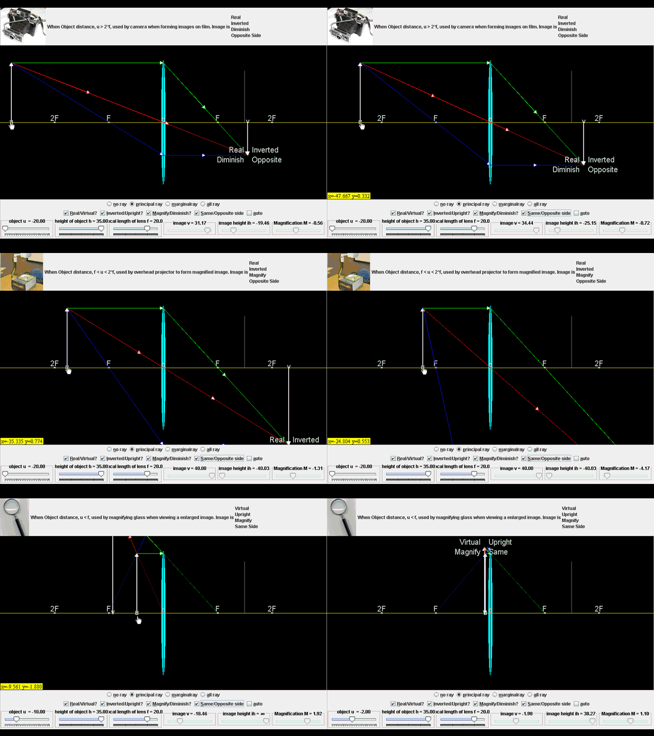
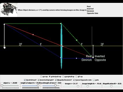
f, used by magnifying glass when viewing an enlarged image. Image is Virtual Upright Magnify Same Side 2F F F 2F Virtual Upright Magnify Same no ray principal ray marginalray all ray Real/Virtual? Inverted/Upright? Magnify/Diminish? Same/Opposite side auto object u = -2.00 height of object h = 35.00
Datenblatt in eine Dauerschleife. zum Preis: https://shop.agilsense.com/products/hb100?_pos=1&_sid=1d6a24d0d&_ss=r HB100 $16.20 SGD (Singapore-Dollar 1€=1,5SGD) Das dürfte das Datenblatt sein: https://antennatestlab.com/wp-content/uploads/2019/07/HB100-Spec-Sheet-Radar-Sensor-Application-Note-Data-Sheet.pdf
indispensable common-mode voltages within 1.3 V of the positiverail.The for servo loops with a high-side input range ADA4807-1/ADA4807-2/ADA4807-4arefabricatedusingthe TheADA4807-1/ADA4807-2/ADA4807-4inputoperates200mV AnalogDevices,Inc., third generation, extra fast complementary beyondeitherrail.Internalprotectioncircuitrypreventsthe
only, it can make use of audio interfaces, too. If either for the originating or the terminating side (or even both sides) an audio interface is selected, the call control is simply skipped for this particular interface, and the audio interface is immediately set to the connected state. Using the audio
Coil EMC suppression Timer accessories 86 series FOR UL H ORSEPOWER AND PILOD UTY RATINGS Copper side view Copper side view Copper side view S EE“General technical information” page V Contact specification Contact configuration 1 CO (SPDT) 1 CO (SPDT) 2 CO (DPDT) Rated current/Maximum peak current A
scanning or copying on areas outside the actual page con‐ tent (e.g. dark areas between the left-hand-side and the right-hand-side of a double- sided book-page scan). The program also tries to detect misaligned centering and rotation of pages and will automatically straighten each page by rotating it to
. Wenn ein höherer Strom als 6mA geschaltet werden soll, dann gibt es auch fertige Bausteine: Low-Side-Schalter: Die TPIC6x595-Bausteine von TI, die zwischen 100mA und über 1A dauernd "sinken" können, weil es Open-Drain-Ausgänge sind, die Lasten bis 33V/50V (je nach IC) gegen Masse schalten. MICREL bietet hier seine MIC584x-Serie, die allerdings etwas "preisempfindlicher" sind. High-Side-Schalter: Der MIC5891 von Micrel kann je Ausgang bis zu 500mA bei 35V liefern (aber nicht alle Ausgänge gleichzeitig). Alternativen Aus der CMOS-Serie 4000 ist der Typ 4094 zum 74HC595 vergleichbar,
syngo Virtual Cockpit remote assistance directly into your workplace. Benefit from an expert at your side when you need it. MAGNETOM Free.Max · Magnetic Resonance 13 Services Connected scanner While you focus on caring for your patients, we stay connected to care for your MRI. Through innovative service
is referenced to the +ve output, it is convenient to consider the regulated output as the negative side. To help reading the circuit diagrams the two connectors between the power and control pcbs join as follows. PJ14 to PJ18 and PJ20 to PJ19. Power Pcb The main windings are connected either in series
saturation. Voltage Feedback Loop The voltage feedback signal is provided from the TL431 at the secondary side through the photo-coupler to the COMP pin of the LD7536R. Similar to UC3842, the LD7536R would carry a diode voltage offset at the stage to feed the voltage divider at the ratio of RA and RB, that is

 Bild
 Bild
 Bild
 Bild
 Bild
 Bild
 Bild
 Bild
 Bild
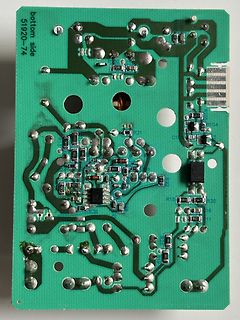
 Bild
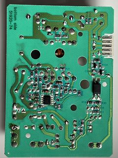
 Bild
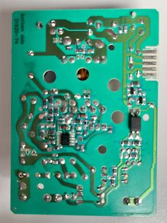
 Bild
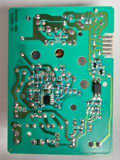
 Bild
 Bild
 Bild
 Bild