-
Datei
pic16f877a.h
OUT OF THE USE OF * THIS SOFTWARE, EVEN IF ADVISED OF THE POSSIBILITY OF SUCH DAMAGE. */ #ifndef _PIC16F877A_H_ #define _PIC16F877A_H_ /* * C Header file for the Microchip PIC Microcontroller * PIC16F877A */ #ifndef __XC8 #warning Header file pic16f877a.h included directly. Use #include <xc.h> instead.
in „HEX-Datei erstellen“ · Mikrocontroller und Digitale Elektronik ·
-
PDF
SC16A_User_s_Manual.pdf
to control particular servo motor. j. Please follow step from b to f. k. Sample source code for PIC16F877A is compatible for PIC16F876A. Cytron Technologies developed based on PIC16F877A is because PICC Lite does not support PIC16F876A. Created by Cytron Technologies Sdn. Bhd. – All Rights Reserved 20
in „Servomotor Steuerung per PIC“ · Mikrocontroller und Digitale Elektronik ·
-
 Bild
Bild
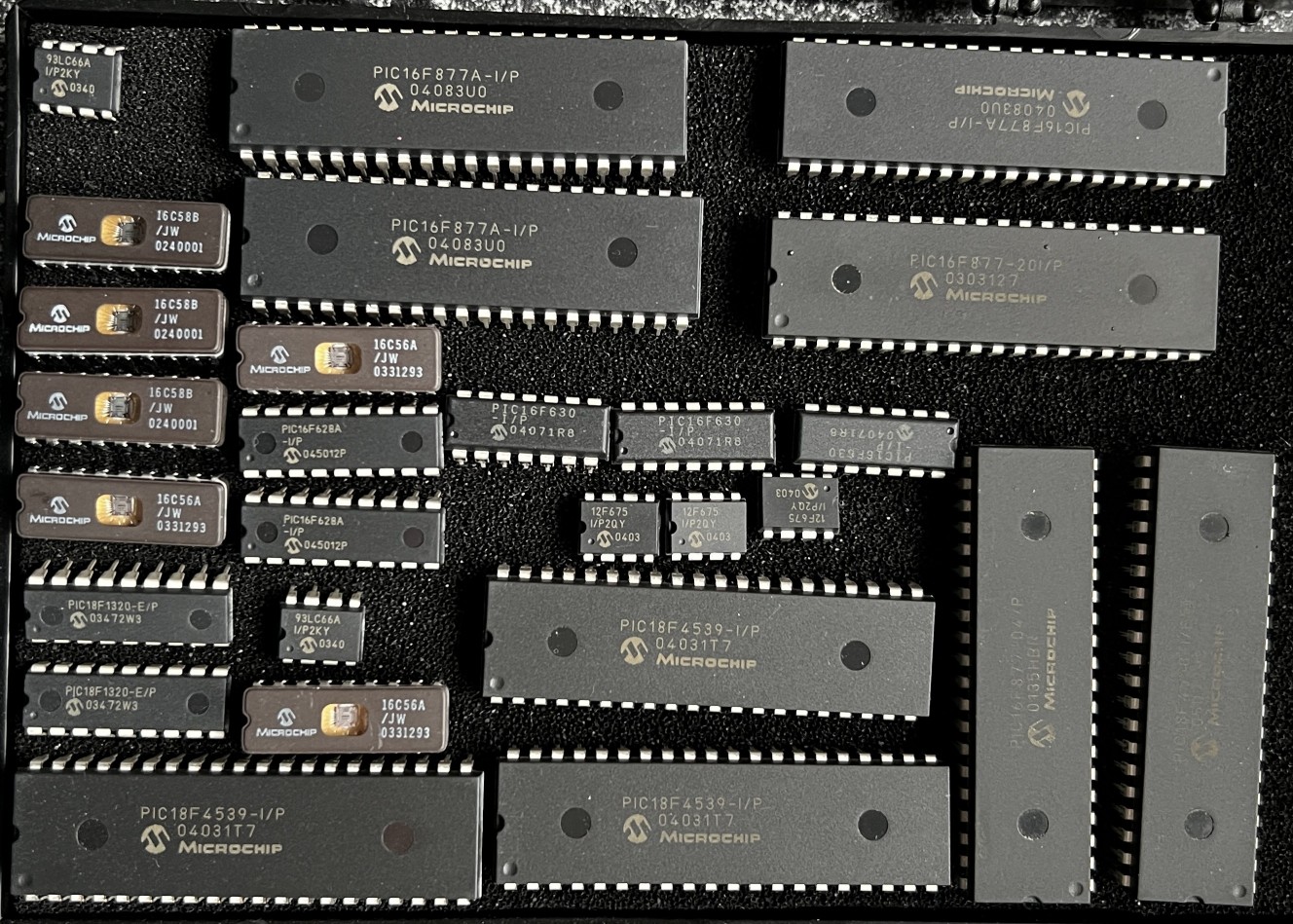
Verschiedene Microchip-Mikrocontroller in DIP-Gehäusen
PIC16F877A-I/P, PIC16F877-20I/P, PIC16C58B, PIC16C56A, PIC16F630, PIC16F628A, PIC18F1320-E/P, PIC18F4539-I/P, MICROCHIP
in „[VS]: Schachtel voll PICs“ · Markt · · Fotos
-
Datei
16F877A.H
// HEADER FILE #if !defined ICD_DEBUG && !defined ICD2_DEBUG #pragma chip PIC16F877A, core 14, code 8192, ram 32 : 0x1FF #elif defined ICD2_DEBUG #pragma chip PIC16F877A, core 14, code 0x1F00, ram 32 : 0x1FF // last 256 locations are reserved for debugging //RESERVED RAM LOCATIONS
in „Servomotor Steuerung per PIC“ · Mikrocontroller und Digitale Elektronik ·
-
PDF
ACB_Datasheet_premininary.pdf
is primarily designed for the PIC18F4550 USB Controller. Other controllers as the pin compatible PIC16F877, PIC18F452, PIC18F458 can also be used with related hardware assembling. 3.2 Power supply Power supply is supported on board but can also provided directly from external power supply. 3.3 Oscillator
in „interessiert an einem PIC18 USB controller board?“ · Markt ·
-
PDF
ACB_Datasheet_premininary.pdf
is primarily designed for the PIC18F4550 USB Controller. Other controllers as the pin compatible PIC16F877, PIC18F452, PIC18F458 can also be used with related hardware assembling. 3.2 Power supply Power supply is supported on board but can also provided directly from external power supply. 3.3 Oscillator
in „interessiert an einem PIC18 USB controller board?“ · Markt ·
-
Datei
AnaltogDigitalConverter.asm
*********************************************************************** list p=16f877 ;Typ-Wahl PIC16F877 #include <p16f877.INC> ;Bezeichnungen von PIC16F877 verwenden ;Errorlevel -302 ;***************************************************************************** ;Konfiguration festlegen __CONFIG 0xA82
in „Analog Digital Converter kleines Problem (PIC)“ · Mikrocontroller und Digitale Elektronik ·
-
PDF
C_fuer_PIC.pdf
*********** Pragma-Anweisungen **************************************************/ #pragma chip PIC16F877 // PICmicro Device /****************** Externe Register ***************************************************/ extern bank0 uns16 tmp_uebergabe_uns16; extern bank0 uns16 sollwert; extern bank0 uns16
in „cc5x und PIC 16F628 / 88 problem“ · Mikrocontroller und Digitale Elektronik ·
-
PDF
Overview.pdf
PIC16F871 PIC16F876 offers cost-effective in-circuit FLASH programming and debugging from the PIC16F872 PIC16F877 graphical user interface of the MPLAB Integrated Development Environment (IDE). PIC16F873 A designer can develop and debug source code by watching variables, setting Contact Microchip Technology’
in „Microchip Programmer Firmware und Updates“ · Mikrocontroller und Digitale Elektronik ·
-
PDF
compactflashOnPicArticle.pdf
for the microcontroller, I chose a you'relookingtocreatea storage, I was both delighted and de- PIC16F877, one of Microchip’s newer digitalpictureframeoran spondent. Delighted because this seemed to end the apparent MP3player, for example, new format indicated its obso- theCFcardcandoit.With lescence
in „COMPACT FLASH-Card“ · Mikrocontroller und Digitale Elektronik ·
-
PDF
compactflashOnPicArticle.pdf
for the microcontroller, I chose a you'relookingtocreatea storage, I was both delighted and de- PIC16F877, one of Microchip’s newer digitalpictureframeoran spondent. Delighted because this seemed to end the apparent MP3player, for example, new format indicated its obso- theCFcardcandoit.With lescence
in „Indentify Drive bei CF-Karte“ · Mikrocontroller und Digitale Elektronik ·
-
Datei
RSKurzeAuswertung.asm
--------------------------------------- ;-----------------------------------Belegung des PICs (PIC 16F877)------------------------- ; ; ________________ ; MCLR 5V--------1| |-------Rel 16 RB7 ; RA0 Kanalsw1------2| |-------Rel 15 RB6 ; RA1 Kanalsw2------3| |-------Rel 14 RB5 ; RA2 Kanalsw3------4| |-
in „PIC nach ändern von Code undefiniertes herumwüten des uC“ · Mikrocontroller und Digitale Elektronik ·
-
Datei
RSKurzeAuswertung.asm
--------------------------------------- ;-----------------------------------Belegung des PICs (PIC 16F877)------------------------- ; ; ________________ ; MCLR 5V--------1| |-------Rel 16 RB7 ; RA0 Kanalsw1------2| |-------Rel 15 RB6 ; RA1 Kanalsw2------3| |-------Rel 14 RB5 ; RA2 Kanalsw3------4| |-
in „PIC nach ändern von Code undefiniertes herumwüten des uC“ · Mikrocontroller und Digitale Elektronik ·
-
PDF
CC5X_Erkenntnisse.pdf
*********** Pragma-Anweisungen **************************************************/ #pragma chip PIC16F877 // PICmicro Device /****************** Externe Register ***************************************************/ extern bank0 uns16 tmp_uebergabe_uns16; extern bank0 uns16 istwert;; /****************
in „PIC 16F877 EEPROM / CC5X“ · Mikrocontroller und Digitale Elektronik ·
-
PDF
Artikel_EN.pdf
ESRismorethan100Ω.AnESRofthis change consists of rewriting the code magnitude makes a capacitor com- for thePIC16F877. pletely unusable in switch-mode cir- thechargingtime. Theresultsaredis- cuits and hardly usable for any other played on a two-line alphanumeric typeof application. Measurement principle LCDmodule
in „ESR Kondensatortester; nur welchen der beiden!“ · Mikrocontroller und Digitale Elektronik ·
-
Datei
16F877A.h
//////// Standard Header file for the PIC16F877A device //////////////// #device PIC16F877A #nolist //////// Program memory: 8192x14 Data RAM: 367 Stack: 8 //////// I/O: 33 Analog Pins: 8 //////// Data EEPROM: 256 //////// C Scratch area: 77 ID
in „HEX-Datei erstellen“ · Mikrocontroller und Digitale Elektronik ·
-
Datei
ProgChangeTest.asm
--------------------------------------- ;-----------------------------------Belegung des PICs (PIC 16F877)------------------------- ; ; ________________ ; MCLR 5V--------1| |40-------Rel 16 RB7 ; RA0 Kanalsw1------2| |39-------Rel 15 RB6 ; RA1 Tast.Up/Kanalsw2------3| |38-------Rel 14 RB5 ; RA2 Tast.Dn
in „trotz org-befehl funktioniert programm-counter tabelle nicht“ · Mikrocontroller und Digitale Elektronik ·
-
 Bild
Bild
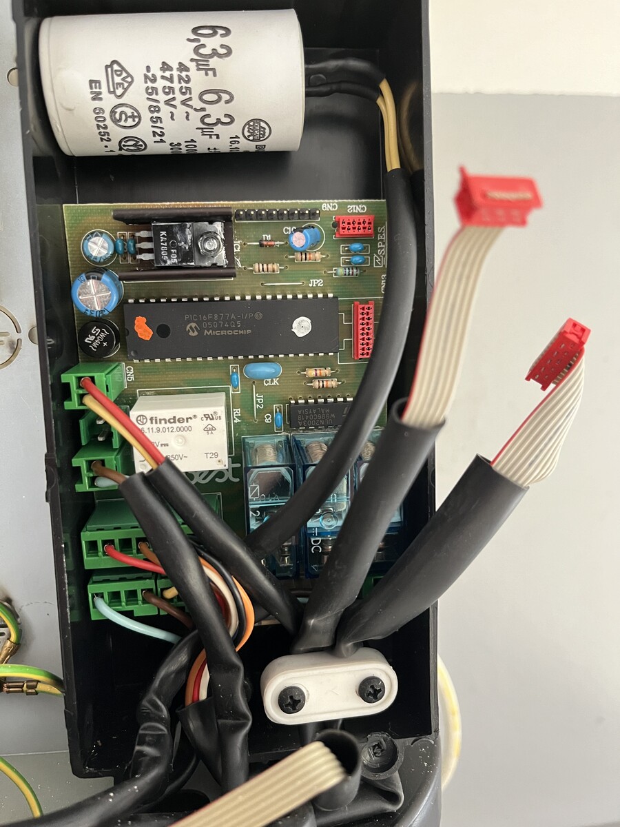
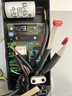
Offenes Elektronikgerät mit Leiterplatte und Elektrolytkondensator
6,3µF 425V~ 475V~ EN 60283-1 PIC16F877A-I/P MICROCHIP finder 11.9.012.0000 T29
in „BEST Dunstabzugshaube - kennt jemand die Platine und hat Unterlagen?“ · Haus & Smart Home · · Platinenfotos
-
Datei
PIC_test.c
#include <PIC16F877.h> void pause() { OPTION = 3; TMR0 = 99; while (TMR0); } void main() { TRISB = 0b.1111.1110; bit out @ PORTB.0; for(;;) { out = 1; for(char i = 0; i < 1000; i++) { pause(); } out = 0; for(char i
in „PIC16F877 geht nicht!“ · Mikrocontroller und Digitale Elektronik ·
-
Datei
led.c
/******************************************************************/ /*LED Demo for PIC16F877 by MH */ /******************************************************************/ void delay(uns8 ms) // Unterprogramm zum Abwarten einer { // angegebenen Anzahl von Millisekunden while(ms){ // Schleife
-
PDF
i2c.pdf
show you a code example to demonstrate I C on the PICmicro device. This example uses a Microchip PIC16F877 device connected to a 24x01x I C EEPROM. We happened to use a 24C01C, but many different devices could be used. These items were chosen since the PICDEM-2 will support the PIC16F877 and it comes
in „PIC16F877 über I2C mit zweitem PIC16F877 verbinden- wie Funktioniert das?“ · Mikrocontroller und Digitale Elektronik ·
-
Datei
printtest.txt
**************************************** Project: PRINT USART Filename: PRINTTEST.c Prozessor: PIC 16F877 Compiler: HI-TECH v8.01PL3 Demoprogramm ***********************************************************************************/ #define __16F877 #include <pic.h> #include <stdio.h> #include "printtest.h
in „Usart + Printf()“ · Mikrocontroller und Digitale Elektronik ·
-
 Bild
Bild
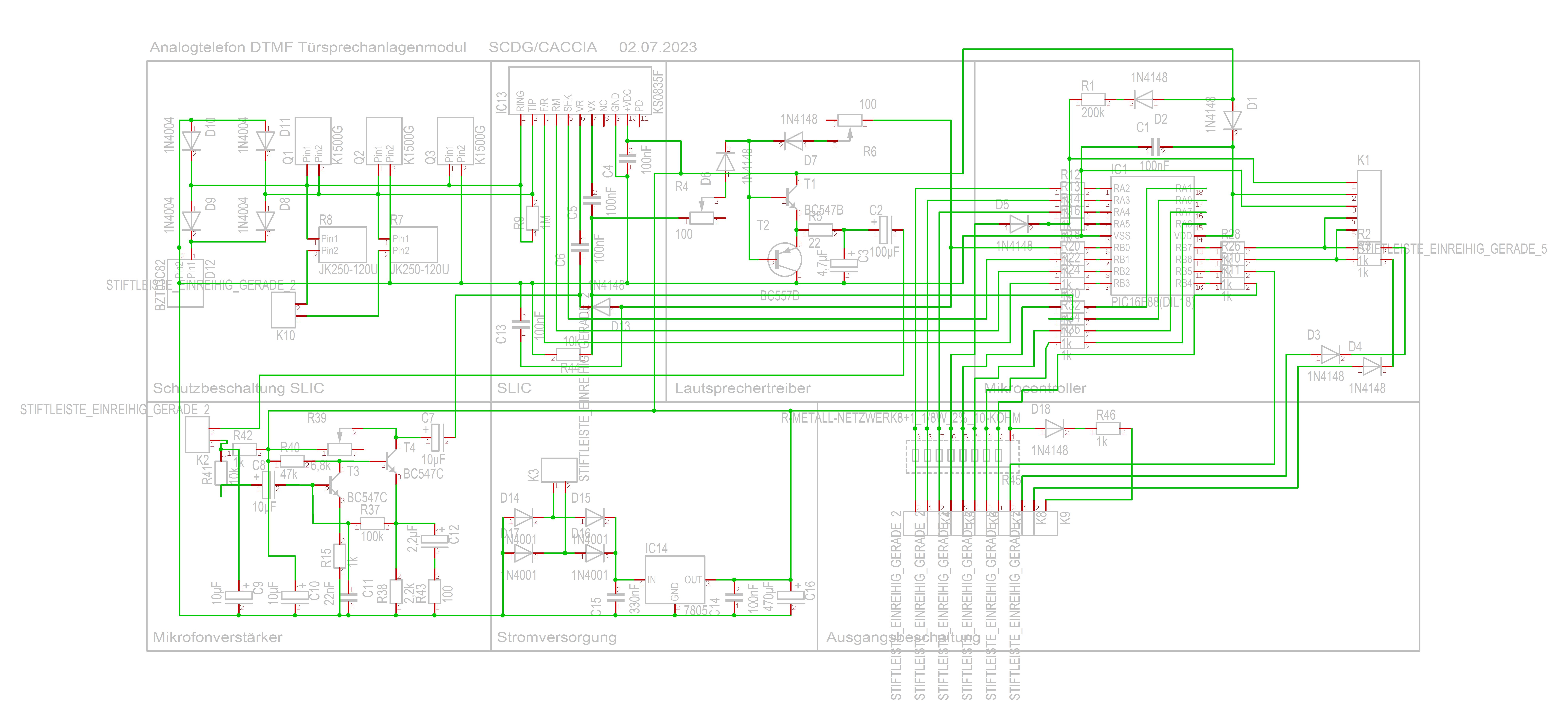
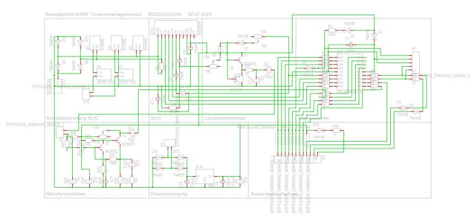
Schaltplan eines Analogtelefon DTMF Sprechanlagenmoduls
100k 1M 10uF 100uF 1nF 10nF 100nF 1uF 10uF 100uF 470uF 10k 100k 1M 1N4001 1N4148 BC547C BC547B PIC16F877A SLIC STIFTLEISTE EINREIHIG GERADE 2 Lautsprechertreiber Mikrofonverstärker Stromversorgung Ausgabeschaltung
in „DTMF Türsprechmodul mit PIC16F8x - Prüfung und Programmierung“ · Mikrocontroller und Digitale Elektronik · · Schaltpläne
-
Datei
main.c
************/ /* i.e. uint8_t <variable_name>; */ //PROGRAMM FOR BLINKING LED // // PROCESSOR : PIC16F877A #include <pic.h> #pragma config FOSC = INTRC_NOCLKOUT// Oscillator Selection bits (INTOSCIO oscillator: I/O function on RA6/OSC2/CLKOUT pin, I/O function on RA7/OSC1/CLKIN) #pragma config WDTE =
in „PIC Anfängerproblem“ · Mikrocontroller und Digitale Elektronik ·
-
PDF
test_40pin.pdf
CCP1 SDO/RC5 24 18 RC3/SCK SDI/RC4 23 19 RD0/PSP0 RD3/PSP3 22 20 RD1/PSP1 RD2/PSP2 21 VSS 1 2 3 1 PIC16F877P 4 1 9 8 7 6 5 4 3 2 1 1 9 8 7 6 5 4 3 2 1 C 1 6 V C 100nF V V + F S S n Port E Port E 1C0nF1 1 9 8 7 6 5 4 3 2 1 1 9 8 7 6 5 4 3 2 1 1 9 8 7 6 5 4 3 2 1 1 9 8 7 6 5 4 3 2 1 S2 1 5 4 1 S S S S IN
in „PIC Assemblerprogramm- Problem“ · Mikrocontroller und Digitale Elektronik ·
-
Datei
Lauflicht_Test.asm
Author: xyz ;********************************************************************** ; Hardware: PIC 16F877 ; Quarzosz. 4MHz ; 8xLED an PORTB RB7:0 ;********************************************************************** ; Projekt: 1 LED an PORTB von RB7 nch RB0 durchlaufen lassen ; nach Erreichen von RB0
in „Lauflicht Pic 16f877“ · Mikrocontroller und Digitale Elektronik ·
-
Datei
Bemerkungen.txt
Sk-Rel-_Rv/_Lv) ohne PIC 4) 1 Modul: AHSS-ESTP-2Ri (Hauptmodul für Haltestellensteuerung) (MASTER-PIC 16F877) 5) 1 Modul: 8-fach Encoder-ESTB (I2C-Verbindung mit Interface --> PC) 6) 2 Module: Div. Led-Lichtsignale mit/ohne VS am Mast-_Rv+_Lv (SLAVE- PIC 16F684) 7) 4 Module: jew. 2*2 Stellpult-Anzeigen
in „HO-Eisenbahn-Schaltmodule“ · Mikrocontroller und Digitale Elektronik ·
-
Datei
1wire.c
zurück a)fM--> b)--> a). 3) 'sStp' (8 bit Datenfluß bidirektional von a)--> c) und zurück. a) PIC 16F877 (Hauptmodul 'AHSS-') - MASTER - b) PIC 16F684 (Schienenschalter-Modul 'Sk/Gbm/Hs') - SLAVE - c) PIC 16F684 (diverse Signal-Module) - SLAVE - d) PIC 12F683 (Anzeige-Module 'SiAn' und RiAn') - SLAVES
in „Serielle Verbindung 2-er PICs“ · Mikrocontroller und Digitale Elektronik ·
-
Datei
RS232_Segmenttest.asm
--------------------------------------- ;-----------------------------------Belegung des PICs (PIC 16F877)------------------------- ; ; ________________ ; MCLR 5V--------1| |-------Rel 16 RB7 ; RA0 Kanalsw1------2| |-------Rel 15 RB6 ; RA1 Kanalsw2------3| |-------Rel 14 RB5 ; RA2 Kanalsw3------4| |-
in „RS232->PIC USART“ · Mikrocontroller und Digitale Elektronik ·
-
PDF
semicon.pdf
Devoices AD7524 JR SO20 100 LM3914 DIP18 99 IC Toshiba TMP91PW12F uC TQFP100 3300 IC Microchip PIC16F877 04/PT LQFP44 354 IC Microchip PIC16F877 20/L LQFP44 20 IC Atmel AT90S4414 4AI LQFP44 640 IC NEC uPD70F3007GC 25 TQFP100 360 IC Xilinx XCS30XL 5TQ 144C TQFP 144 50 IC Sharp LH28F160BJE TTL90 Flash
in „4" TFT für 7,97€“ · Markt ·
-
Datei
RS232_Segmenttest.asm
--------------------------------------- ;-----------------------------------Belegung des PICs (PIC 16F877)------------------------- ; ; ________________ ; MCLR 5V--------1| |-------Rel 16 RB7 ; RA0 Kanalsw1------2| |-------Rel 15 RB6 ; RA1 Kanalsw2------3| |-------Rel 14 RB5 ; RA2 Kanalsw3------4| |-
in „PIC nach ändern von Code undefiniertes herumwüten des uC“ · Mikrocontroller und Digitale Elektronik ·
-
Datei
switch.c
//NCSOS 0.0.1 //operating system for the HomeAutomation Switch //using a PIC 16F877A #include <16F877A.h> #fuses HS,NOWDT,NOPROTECT,PUT,NOLVP,NODEBUG,NOBROWNOUT,NOCPD,NOWRT //switch running at 20Mhz #use delay(clock=20000000) //defination of the standard output interface #use rs232
in „RS232 - ( PIC 16f877a )“ · Mikrocontroller und Digitale Elektronik ·
-
Datei
bootldra.asm
;--start email from Herman Aartsen-- ;Dear Shane, ; ;Although I'm still very positive about the PIC16F877 boatloader I have ;recently expierenced a very nasty side effect I think others should know about ;it before they start using it for their rocket detonators, breathing devices ;etc. ; ;At the research
in „PIC16f876A bootloader frage“ · Mikrocontroller und Digitale Elektronik ·
-
Datei
PICkit_3_Programmer_Application_ReadMe.txt
PIC16F87# PIC16F88# PIC16F818# PIC16F819# PIC16F870 PIC16F871 PIC16F872 PIC16F873 PIC16F874 PIC16F876 PIC16F877 PIC16F873A PIC16F874A PIC16F876A PIC16F877A PIC16F882# PIC16F883# PIC16F884# PIC16F886# PIC16F887# PIC16F913# PIC16F914# PIC16F916# PIC16F917# PIC16F946# Midrange/1.8V Min Devices ---------------
in „PICkit3 und Windows 11“ · Mikrocontroller und Digitale Elektronik ·
-
Datei
Bootldr.txt
implement a long jump. Below is a typical memory map with the bootloader installed. Microchip PIC 16F877 memory map with the bootloader installed Address 0 ---------------------------- | Jump to bootloader | <--- Bootloader uses 1st 4 words (0-3H) 4 |--------------------------| | | | | | | | | | | |
-
Datei
8bit.asm
Projekt : Ansteuerung Display 8 Bit ;* ;* Autor : T. Bührer ;* Datum : 3.8.2009 ;* ;* Controller : PIC 16F877A ; ;* Oszillator : 4 MHz (XT) ;* ;* Beschreibung : ;* ;* ;* ;*************************************************************** ; list p=16f877, st=OFF, x=OFF, n=0 errorlevel -302 #include <p16f877.
in „LCD-Ansteuerung funktioniert nicht“ · Mikrocontroller und Digitale Elektronik ·
-
Datei
RS232_Segmenttest.asm
--------------------------------------- ;-----------------------------------Belegung des PICs (PIC 16F877)------------------------- ; ; ________________ ; MCLR 5V--------1| |-------Rel 16 RB7 ; RA0 Kanalsw1------2| |-------Rel 15 RB6 ; RA1 Kanalsw2------3| |-------Rel 14 RB5 ; RA2 Kanalsw3------4| |-
in „Verständnisfrage PIC-Stack“ · Mikrocontroller und Digitale Elektronik ·
-
Datei
RS232_Segmenttest.asm
--------------------------------------- ;-----------------------------------Belegung des PICs (PIC 16F877)------------------------- ; ; ________________ ; MCLR 5V--------1| |-------Rel 16 RB7 ; RA0 Kanalsw1------2| |-------Rel 15 RB6 ; RA1 Kanalsw2------3| |-------Rel 14 RB5 ; RA2 Kanalsw3------4| |-
in „Verständnisfrage PIC-Stack“ · Mikrocontroller und Digitale Elektronik ·
-
Datei
i2c.c
- vorgänge bereits implementiert und müssen nicht gesondert aufgeführt werden. Die verwendeten PIC 16F877 und 16F690 haben ge- nannte 'MSSP-Module', der andere verwendete PIC muß entsprechend geändert bearbeitet werden. */ void i2c_Stop(void) { SDA_LOW(); // SDA=0 SCL_HIGH(); // SCL=1 DelayUs(I2C_TM_DATA_SU
in „Serielle Verbindung 2-er PICs“ · Mikrocontroller und Digitale Elektronik ·
-
PDF
300W-Inverter.pdf
FREI7 39 RD1/PSP1 RD2/PSP2 40 FREI8 X2-13 DISP12 VSS R42 R37 R73 1k 9 6 PIC-OUT U4_5 X2-14 DISP13 2 PIC16F877 10k 510 1k 6 k C21 3 0 C20 R 2 R 3 GND GND GND 300W Inverter V + 3 U6A VR1 k 5 1 10k 4 R 2 3 1 U4_6 U4_7 R28 R1 LM358D 2 PIC/AN1 PIC/AN0 BATTERY_FUSED 390k 470k 6 0 C4 P C9 6 k R 2 E T k 3 R 6 T
in „$40 GDI inverter, neuerdings qualitätsprobleme?“ · Haus & Smart Home ·
-
PDF
300W-Inverter.pdf
FREI7 39 RD1/PSP1 RD2/PSP2 40 FREI8 X2-13 DISP12 VSS R42 R37 R73 1k 9 6 PIC-OUT U4_5 X2-14 DISP13 2 PIC16F877 10k 510 1k 6 k C21 3 0 C20 R 2 R 3 GND GND GND 300W Inverter V + 3 U6A VR1 k 5 1 10k 4 R 2 3 1 U4_6 U4_7 R28 R1 LM358D 2 PIC/AN1 PIC/AN0 BATTERY_FUSED 390k 470k 6 0 C4 P C9 6 k R 2 E T k 3 R 6 T
in „Wie ist ein billiger Grid Tie Inverter aufgebaut ?“ · Analoge Elektronik und Schaltungstechnik ·
-
Datei
DKW.c
/*-------- Programm 'DKW.c' -- 12.01.2011. MASTER (PIC 16F877) hat einen MSSP-Modul (I2C) /*die diesem Programm zugrunde liegenden Anweisungen stammen aus dem HI-TECH-Compiler (PICCLITE) (i2c.c, usw.) Funktionsweise dieses Modules, siehe 'DKW-Text.text' PIC
in „HO-Eisenbahn-Weichenmodul“ · Mikrocontroller und Digitale Elektronik ·
-
PDF
PIC_K150_Manual.pdf
PIC16F871 PIC16F872 PIC16F873 PIC16F873APIC16LF873APIC16F874 PIC16F874APIC16F876 PIC16F876APIC16F877 PIC16F877A 18 系列: PIC18F242 PIC18F248 PIC18F252 PIC18F258 PIC18F442 PIC18F448 PIC18F452 PIC18F458 PIC18F1220 PIC18F1320 PIC18F2220 PIC18F2320 PIC18F2321 PIC18F4210 PIC18F2331 PIC18F2450 PIC18F2455 PIC18F2480
in „Anfänger Problem Programmer für PIC“ · Mikrocontroller und Digitale Elektronik ·
-
PDF
illustrated_assembly_manual_k8048_rev4.pdf
PIC16F870, PIC16F871, PIC16F872, PIC16F873, PIC16F873A, PIC16F874, PIC16F874A, PIC16F876, PIC16F876A, PIC16F877(A)(ICSP only) PIC16F627, PIC16F627A, PIC16F628, PIC16F628A, PIC16F648A PICF630, PIC16F676 PIC16F818, PIC16F819 Dimensions: 145 x 100mm (5.75" x 4") Minimum system requirements: IBM Compatible PC,
in „Spannungspegel am RS232 zu niedrig! MAX232?“ · Analoge Elektronik und Schaltungstechnik ·
-
PDF
illustrated_assembly_manual_k8048_rev3.pdf
PIC16F870, PIC16F871, PIC16F872, PIC16F873, PIC16F873A, PIC16F874, PIC16F874A, PIC16F876, PIC16F876A, PIC16F877(A)(ICSP only) PIC16F627, PIC16F627A, PIC16F628, PIC16F628A, PIC16F648A PICF630, PIC16F676 PIC16F818, PIC16F819 Dimensions: 145 x 100mm (5.75" x 4") Minimum system requirements: IBM Compatible PC,
in „Velleman K8048: ERROR! K8048 not found in COM1“ · Mikrocontroller und Digitale Elektronik ·
-
Datei
Quelle.htm
Programme, Atmel, AVR,PIC16F870, PIC16F871,PIC16F872,PIC16F873,PIC16F874,PIC16F876, PIC16F877,PIC16F84,PIC16F84A" name=keywords> <META content=2003-05-12 name=date> <STYLE>P.MsoNormal { FONT-SIZE: 10pt; MARGIN: 0cm 0cm 0pt; FONT-FAMILY: "Times New Roman"; mso-style-parent: ""; mso-pagination
in „Dateizuordnungstabelle in FAT16“ · Mikrocontroller und Digitale Elektronik ·
-
PDF
top2008.pdf
PIC16CR84, PIC16F84, PIC16F84A, PIC16F870, PIC16F871, PIC16F872, PIC16F873, PIC16F874, PIC16F876, PIC16F877, PIC16F873A, PIC16F874A, PIC16F876A, PIC16F877A, PIC16F818, PIC16F819, PIC16F882, PIC16F883, PIC16F886, PIC16F884, PIC16F887, PIC16F913, PIC16F916, PIC16F914, PIC16F917, PIC16F722, PIC16F723, PIC16F726
in „[V] Top 853 Universal Programmer + 74er Tester“ · Markt ·
-
Datei
glipict2_bas.htm
application for use with a T6963C (or compatible) 'graphic LCD controller connected to a Microchip(TM) PIC 16F877 'Written in MELabs PicBasicPro(TM) Ver 3.32 'Beta version 0.8.0 'SHARP LCD used: 240x64 graphic LCD (EL backlight) '================== NOT FOR COMMERICIAL USE ============================= ' ' Author
in „T6963c Display Problem“ · Mikrocontroller und Digitale Elektronik ·
-
Datei
Values.txt
REICHELT_VFI353 2 RECTIFIER-B40S 2 r9 2 PWR 2 PV8251 2 PR1003 2 Power Out 2 POWER 2 PIN3F061.120 2 PIC16F877P 2 PIC16F874P 2 PG203J 2 PCA82C250 2 P6KE200A 2 OPA2333 2 OPA1632 2 OP11P 2 Netz 2 NE567 2 NE555N 2 NE5532 2 MT48LC8M16A2 2 MSTBV3 2 MOSFET-P-4D-FDC604P 2 MOC3021 2 ML10 2 MEGA8L-P 2 MEGA323-A 2
in „[KiCad] Bibliotheksaufbau - Konzeptideen gesucht“ · Platinen ·
-
Datei
Devices.txt
2.54-SMD 2 PINHD-2X10 2 PINHD-1X7 2 PINHD-1X2/90 2 PINHD-1X1_2.54 2 PINHD-1X12 2 PIN3F061.120 2 PIC16F877P 2 PIC16F874P 2 PG203J 2 PCA82C250 2 PC817 2 OSZILLATOR 2 OPA2333 2 OPA1632 2 OP11P 2 NPN-TRANSISTOR_SOT23W 2 -NPN-TO92-ECB 2 -NPN-TO225AA 2 NPNSOT89 2 NPNSOT323 2 N-MOSFET-SO8 2 NE567 2 NE555N 2
in „[KiCad] Bibliotheksaufbau - Konzeptideen gesucht“ · Platinen ·