Mf a / ___ dl 8 14/9 3/7 l<— — O l £ Ol - A n BF®f2 ■ KfrOTe RüK M ? 2$ CVr ER E s-m i - & ' CI " c 4 \ 01 b 2 fe: i l^iiT kl Br % ‘-b%‘ RüVr ü § v I SK * -O - i C5 ,.C8 ^ -7 Z Z -c 1 FspG StrVG 65 V—(1) o o- <4/9 fZ/9 51 ± i ■iB 65 V—(2) o o <3/7 JJ M Bild 3: Antennenkomplex der Hamburger BK-Anlage
Microchip PolarFire Family FPGA Security User Guide: https://onlinedocs.microchip.com/oxy/GUID-DF33D7C4-5604-4C6B-92AF-8C864323C016-en-US-14/index.html Von dem was ich bisher in die Finger bekommen habe, ist das der FPGA mit den weitreichensten Security Features. Er kann z. B. ein X509 Zertifikat zurückliefern
gerade eben eine Heizungssteuerung aus den 90ern zu quasi-OpenSource (vom Binary zu recompilierbarem C-Code).
time at 12 MHz programmable Baudrate-Generators – 666 ns instruction cycle time at 18 MHz l Fully upward compatible with SAB 80C515, – 256 directly addressable bits SAB 80C517, SAB 80C515A – Boolean processor
Serial PROM AT24C08A NONE No Need WSPROM V6.06 ATMEL Serial PROM AT24C1024 NONE No Need WSPROM V6.06 ATMEL Serial PROM AT24C128 NONE No Need WSPROM V6.06 ATMEL Serial PROM AT24C16/AT24C164 NONE No Need WSPROM V6.06 ATMEL Serial PROM AT24C16A NONE No Need WSPROM V6.06 ATMEL Serial PROM AT24C21 NONE No Need WSPROM V6.06 ATMEL Serial PROM AT24C256 NONE No Need WSPROM V6.06 ATMEL Serial PROM AT24C32 NONE No Need WSPROM V6.06 ATMEL Serial
mit AT89C2051, AT89C4051 oder AVR AT90S2313, CPU-Board mit Atmel AT90S8535, Experimentierplatine mit ATmega103, Programmer für AT89C2051/AT89C4051, 32-Kanal-Logik-Analysator bis 40 MHz (Entwurf von David L.
Steuerung von Videorekordern oder Camcordern über das Control-L (LANC) Protokoll mit Hilfe eines AT89C2051. Microcontroller-Starterkits Starter-Kits für verschiedene Microcontroller (D) preisgünstige Platinen (ab 12,95 Euro für AT89S8252). Beim uC-Dualboard : Das Board ist nutzbar mit AVR-Controllern
provides power ratings from 0.5 W to 6 W at 70°C. The series supports tolerances to 0.1%, TCR as low as 25 ppm/°C, a 50 ohm to 30.1 kilohm resistance range, and operation from -55°C to +155°C. Performance testing reinforces its suitability for long service life: resistance shift is specified at ±1% after 1000 hours of endurance, ±0.4% after 1000 hours of damp heat with load, and ±0.2% after 100 thermal-shock cycles from -55°C to +150°C. [/c] 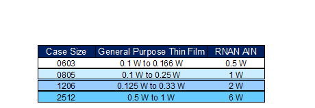 Bildquelle: Stackpole
LED video or irregular screen. VDD feet when under 24V power supply. l Gray level 256 can be adjusted and scan freque ncy not less than 400Hz/s. l Built in signal reshaping circuit,after wave resha- ping to the next driver, ensure wave-form distor- tion
das Adapterboard STEVAL-MKI258KA für die ISM6HGK256X werden bis November 2026 im eSTore und über Distributoren verfügbar sein. Die LSM6DSK320X für Consumer-Anwendungen arbeitet über einen breiten Temperaturbereich von -40 °C bis +85 °C. Die industrietaugliche ISM6HGK256X beherrscht Temperaturen von -40 °C bis +105 °C und ist Teil des 10-Jahres-Langzeitverfügbarkeitsprogramms von ST, das die langfristige Verfügbarkeit von Komponenten sicherstellt. Die IMUs sind in
Carsten-Peter C. schrieb im Beitrag #8098439: > Moin, > warum kann man mit einem Byte keine 256 Byte SRAM adressieren? Wenn man bei Adresse 0 anfängt ja, sonst nicht.
die zu SP gehörige 16-Bit RAM Adresse als [c]addr = SPL + 256 * (SPL < 0x60) // 1[/c] oder als [c]addr = 0x60 + SPL // 2[/c] zu berechnen wäre. Weder das eine noch das andere ist der Fall. Zumindest gab's die letzten 25 Jahre keinen entsprechenden
switches and a dedicated host power switch • 256 byte SRAM for data logging • Three channel ADC with battery monitoring • 32 bit timer and alarm • Watchdog and event counter • Operating temperature range of −40°C to +85°C • Power aware operation
offers a high slew rate of 180V/μs, excellent distortion (spurious-free dynamic range (SFDR) of −100dBc at 1MHz), extremely high common-mode rejection ratio (CMRR) of −100dB, and a low input offset voltage of 3mV maximum under warmed up conditions. [/c]
manual of your µC. #define USB_IRQ_NUMBER 20 // Buffer for sending characters, txLen must be 4, 8, 16, 32, 64, 128, 256, 512, 1024, 2048, ... #define USB_TXLEN 256 // Buffer for received characters, rxLen must be 128,
PANASONIC bei https://www.reichelt.de/de/de/shop/produkt/elko_radial_1000_f_25v_105_c_low_esr_aec-q200-376206?PROVID=2788&gad_source=1&gad_campaignid=1622074784&gclid=EAIaIQobChMIjbL6_Ki-lgMV489EBx1u8AT4EAQYASABEgIWpvD_BwE
welcher Zeit? Egal? Stunden? Sekunden? Blick ins DaBla zeigt: Leakage Current I <= 3 * sqrt(C * V) (in μA) (After 5 minutes' application of rated voltage at 20°C) [C : Rated Capacitance (μF) V : Voltage (V)] Wie passt das jetzt mit der Anzeige deines Gerätes zusammen? Alles was das 10 €
Für fast alle Wettersensoren gibt's ebenfalls Libraries und Module. Ein SHT35 kümmert sich um °C und %rF, der BMP280 kann mmHg, beide passen zusammen an einen I²C-Port. Ein FRAM mit MB85RC256 passt ebenfalls noch mit an den I²C und hat 32kByte Platz. Achtung: je nach Arduino brauchts einen Pegelwandler
Datensatz geschrieben, dann sind dies 31gb im Monat. Die Annahme bezieht sich auf zwei Lichtschranken, 24bit Datensatz und zwei Durchgänge je Sekunde, sowie weiteren 3minuten Datensätzen. Mit zusätzlichem i2c EEPROM und einer zweiten SD Karte sollte die Daten einfach alle 10tage abgeholt werden. Dies sehe
0 0 0 X X X Offset Register Character Code (00~FF) Cell scan line (lower 5-bits only) set by T6963C For example to load up the character pattern for the pound #i” to character code 0FH in the CG-RAM area starting at 1C00H. The Address Pointer should be set to 1C78H by the Address Pointer Set command
The hardware interrupt occurs during the address calculation period (at the end of each line). If a MSB = 0 command is sent to the T6963C during this period, the T6963C enters Wait status. If a status check is not carried out in this state before the next command is sent
data[0], (int16_t)data[1], (int16_t)data[2]); BME280_CalculateTemperature (RawTemp, &FineTemp, &DegC100Temp); /* ** Do the compensation computation as of Bosch documentation page 25. ** Computes the pressure in unsigned 32 bit integer in Q24.8 format (24 integer bit, 8 fractional bits). ** Example:
R5/C1 nicht bestückt und stattdessen R15 (NucleoShield) bzw R16 (MiniDevShield) mit 100k bestückt. WS2812. Bei der WordClock24h wird eine 16x18-Matrix verwendet plus eine Status LED, bei der WordClock12h
--O--+ | | | | | O--O--O--O--O--O--O--O--O--O--O--O--O--O--O--O-- | 37 38 .... | | | Status-LED | µC Data -----------------------------O-------------------------------+ Auch für die WC24h gilt: Beim (für die WC24 primär empfohlenen) Nucleo-Board und beim (ebenfalls für die WC24h nutzbaren) BluePill
Keil8051 (teuer). Ach ja, und mir fehlt die passende Anwendung für die alten Dinger. Habe noch 65 Stck. At89C52ED2, die waren mir vor 15 Jahren Gold wert aber heute?
LED Strom in SOP20/SOP28. und bis 12V auch an den Eingängen/Ausgängen arbeiten Micronas HVC22xyA HVC24xyA und Infineon TLE7810G und Holteks HT66F2730 hat einen Spannungsregler drin Oder bis 300 GradC arbeitende https://www.blikai.com/productdetail/honeywell-aerospace-ht83c51-2046731
was already automatic 6. Clear out any manual entries → no entries were present 7. Restart Pi [c] AT+QCFG="usbnet" +QCFG: "usbnet",1 AT+QNETDEVCTL? +QNETDEVCTL: 3,1,1,1 AT+QNETDEVCTL=3,1 OK AT+QNETDEVCTL? +QNETDEVCTL: 3,1,0,1 user@chupi:~ $ systemctl status NetworkManager ● NetworkManager.service
560 VDC DC Voltage Capacitance Range 0.010 – 10 µF Capacitance Values E6 series (IEC 60063) measured at 1 kHz and +20±1°C Capacitance Tolerance ±10%, ±20% Operating Temperature Range −40°C to +110°C Rated Temperature +110°C Climatic Category 40/110/56 IEC 60068-1 Storage time: ≤ 24 months from the date
following compression directives c.lbu/c.lhu/c.sb/c.sh/c.lbusp/c.lhusp/c.sbsp/c.shsp,usebasedontheMRScompilerorthetoolchainitprovides. 1.2 Register set RV32E is a subset of RV32I, which has only half of its registers. That is, there are
Rev 1.2 Time base and Watchdog Timer (WDT) The time base generator and WDT share the same divided (/256) counter. TIMERDIS/EN/CLR, WDT DIS/EN/CLR and IRQ EN/DIS are independent from each other. Once the WDT time-out occurs, the IRQ pin will remain at logic low level until the CLR WDT oIRQhe DIS command
from the exact same halted state (`*_run2.bin`) and compare. All three pairs are byte-identical (SHA-256): ``` nrf51_flash.bin 65C3295826B331CDB87B13042698878C66C7FD241FBD87CE1878F8E44123A470 nrf51_ram.bin 36EF8B35EDC1158F4BAFBDECB8BBD628B1CF91F219B08067028156E92164D69C nrf51_uicr.bin 3D6876A0146DE8576EB2395A858DE1213D1B92C65B779DF3A331CFD5A4584546
at 0x35C00 Has its own valid vector table (SP `0x20003498`, Reset `0x35d29`) with handler addresses self-referential to the `0x35C00` region, so it is linked to execute there — not a staged copy of the
Logarithmisches 100k Digitalpoti, her damit. Ein logarithmisches Digitalpoti mit 32 kΩ wäre bspw. das X9C303 von Renesas https://www.renesas.com/en/document/dst/x9c303-datasheet?r=502681 Von Dallas gab es 100 kΩ "pseudo-logarithmisch" das DS1666S-100, zwar nicht logarithmisch, aber mit abschnittsweise
Rainer W. schrieb im Beitrag #8070077: > Ein logarithmisches Digitalpoti mit 32 kΩ wäre bspw. das X9C303 von > Renesas > https://www.renesas.com/en/document/dst/x9c303-datasheet?r=502681 Gar nicht schlecht für ein verfugbares Teil, simuliert einen 10k NTC von knapp 0 bis 100 GradC, wegen bis zu
MHz maximum internal clock frequency ■ Oscillator supervisor ■ Fully static operation HiQUAD64 ■ -40°C to + 150°C temperature range ■ User EPROM/OTP: 16 Kbytes ■ Data RAM: 256 bytes ■ 10-bit analog-to-digital converter ■ Data EEPROM: 128 bytes ■ Software watchdog for system integrity ■ 64 pin HiQUAD64
89 up to 128 up to 156 Single supply voltage 2.7 - 5.5 V 2.7 - 5.5 V Ambient Operation Temperature aT ) -40 C to +105 C / +125 C -40 C to +105 C / +125 C Flash 128 KB 256 KB 256 KB 512 KB 1 MB 2 MB 2 Error Correcting Code (ECC) System RAM (including FlexRAM and MTB) 17 KB 25 KB 32 KB 64 KB 128 KB 256
D904 T 65 106 C315 B 131 58 C703 T 175 24 C839 T 41 69 C1001 T 90 40 D905 T 63 106 L805 T 40 36 R211 B 87 66 R627 T 43 20 C316 B 132 60 C704 T 176 24 C840 T 182 14 C1002 T 89 41 D906 T 62 106 L806 T 40 47 R212 B 86
0F65 C 4 0 0 LDI 00 0FA45 3 F XPPC 3 0 F 2 6 C417 LDI17 3 1 XPAL 1 C 0 0 F LD HOURS 0 F 2 8 33 XPAL3 0F67 C 0 4 A LD SEC 0 F 2 9 C40F LDI 0F 0F6A 0 2 CCL 0FA87 0 3 2 4 SCL 24 0 F 2 B 37 XPAH 3 B E C 0 1 DAI
is optimized for use in many AT24C01A industrial and commercial applications where low power and low voltage operation are essential. The AT24C01A/02/04/08/16 is available in space saving 8-pin PDIP, AT24C02 (AT24C01A/02 /0 4/08 /1 6), 8-Pin MSOP (AT24C01A/02), 8-Pin TSSOP (AT24C01A/02/04/08/16), and 8-Pin and 14-Pin JEDEC SOIC (AT24C01A/02/04/08/16) packages and is accessed via a 2-wire serial interface. In AT24C04 addition, the entire family is
a single XML file Web Server, ZeroConf, Auto-IP, Messenger, IPv4/IPv6, … Questions: FRDM-K64F (ab 24 Euro). Ethernetbuchse eingebaut ARM® Cortex™-M4 Core with Floating point unit and DSP 120MHz, 256KB RAM, 1MB FLASH SPI (3) I2C (3) I2S UART (5) USB OTG / Host / Device USB regulator PWM ADC (2x 16bit
Uno (ca. 24 EUR) mit Ethernet Shield (ca. 35 EUR) oder Arduino Ethernet (ca. 48 EUR) private Projekte. avrETH1. winzige Maße: 32mm x 47.8mm x ~20mm (BxLxH) Microchip ENC28J60 Ethernetcontroller Atmel Atmega32 uC
M27C2001 2 Mbit (256Kb x 8) UV EPROM and OTP EPROM Features ■Access time: 55nsoltage in R32d operat32n ■– Active Current 30mA at 5MHz FDIP32W (FPDIP32 (B) – Standby Current 100µA c ts ■Programming time: 100µs
ADC0805 ± 1 LSB www.national.com 2 A D Absolute Maximum Ratings (Notes 1, 2) Infrared (15 seconds) 220˚C C 8 If Military/Aerospace specified devices are required, Storage Temperature Range −65˚C to +150˚C 0 please contact the National Semiconductor Sales Office/ Package Dissipation at T25˚C 875 mW / A A
hängt eine zu steuernde LED. Der kommt aber vorallem beim faden der Glühbirnensimulation mit seiner 256 Kanal PWM an seine Grenzen. Die Stufen sind vorallem beim auf oder nachglimmen eindeutig erkennbar. Das ist so nicht akzeptabel. Je Platine sind maximal 14 Leds zu treiben. Angesteuert von einem AtMega328P
allerdings speziell mit der Arduinowelt zu tun hat, ist irgendwie nicht klar. Der wird ganz normal per I²C gesteuert. Oder an welchen Arduino dachtest du, der die Fast-mode Plus Version des I²C-Interface unterstützt, falls man die wegen der Updategeschwindigkeit nutzen möchte/muss? Nico schrieb im Beitrag
