Loco M. schrieb im Beitrag #8090013: > Wenn auf dem Bild Hall_Sensor_Platine_back das Teil rechts neben > dem mittleren Kondensator ein Lötzinnüberrest ist, dann fehlt nicht viel > bis zum Kurzschluss
BirnKichler 🧐 S. schrieb im Beitrag #8095486: > ist da ein mc verbaut? M9S8AC16C0 VoRNI XNCJ1312 Oder ähnlich. Kann man auf den Fotos sehen
die „neueste“ Version des auch immer populärer werdenden Protokolls unterstützt: [c] The Summit™ M616 PCIe Protocol Analyzer/Exerciser platform is now PCI Express 7.0-ready, giving engineering teams a clear upgrade path for PCI Express 7.0 validation and debug. Utilizing a new modular approach, Summit M616 users can extend their system to support PCIe 7.0 development workflows as the ecosystem advances toward 128 GT/s operation. [/c] ### Microchip CSAC-SA65 – „nuklearer“ Zeitgeber für die Satelliten-Elektronik
23 22 21 20 19 18 17 16 R E E E E E E E E e e R W R W R W R W r S U r S W 7 7 6 6 5 5 4 4 s 3 3 s 2 M M M M M M M M e M M e M R R Reset 0 0 0 0 0 0 0 0 0 1 1 0 0 0 0 1 Bits 15 14 13 12 11 10 9 8 7 6 5 4 3 2 1 0 R M M E M M E M M 2 U 1 1 U 0 0 U W M M M M M M M M Reset 1 1 1 1 0 1 1 1 1 1 0 1 1 1 1 1
der richtigen (Isolations-) Abstände abhängig von der Einsatzhöhe geht würde ich gleich die für 4000 m ü.NN wählen. Die sind nicht übermäßig härter als die fürs deutsche Flachland aber ermöglichen auch eine bedenkenarmen Einsatz in Kolumbien, Tibet, ... Braucht man praktisch eher selten, aber Abstände
wird üblicherweise auch auf eine effektive Höhe von 10.000 Fuß, d.h. die besagten 3050 m eingestellt. Gerade bei kleinen, portablen, batteriegespeisten Geräten sollte man also durchaus beachten, dass sie sich an Board solch eines Flugzeugs befinden können und (unbeabsichtigt) eingeschaltet
SUPPORT Dissipation factor 7 For complete Curve Computation, visit: (for information only) 8.5 mW/K www.vishay.com/resistors-non-linear/curve-computation-list/ (for 25-value 680 ) Maximum power dissipation 500 mW MARKING at 55 °C Climatic category The thermistors are marked with colored bands
low voltage V IL V V CC= 2.2 to 3.6 V –0.3 — 0.15VCC 2, 3 Output high voltage (1) V OH1 V IOH= –0.1 mA 0.75VCC — — 2 (DB0-15 pins) Output low voltage (1) V CC= 2.2 to 2.4 V, — — 0.2 VCC 2 (DB0-15 pins) I = 0.1 mA V OL1 V OL VCC = 2.4 to 3.6 V, — — 0.15VCC 2 IOL= 0.1 mA Driver ON resistance R SEG kΩ ±Id = 0.05 mA, — 0.35 3 4 (SEG pins) V LCD= 3 V Driver ON resistance R COM kΩ ±Id = 0.05 mA, — 0.90 3 4 (COM pins) V CH - VCL 44 V I/O leakage current ILi µA Vin = 0 to CC –1 — 1 5 Current consumption IOP µA R-C
SUPPORT Dissipation factor 7 For complete Curve Computation, visit: (for information only) 8.5 mW/K www.vishay.com/resistors-non-linear/curve-computation-list/ (for 25-value 680 ) Maximum power dissipation 500 mW MARKING at 55 °C Climatic category The thermistors are marked with colored bands
400Hz/s. Cascading port transmission signal by single line. Any two point the distance more than 5m transmission signal without any increase circuit. When the refresh rate is 30fps, cascade number are not less than1024 points. Send data at speeds of 800Kbps. The color of the light were highly
348 BC 349 BC 382 BC 383 BC 384 BC 407 BC 408 BC 409 - BC413 - BC 414 - - BC 437 BC 438 BC 439 BC 467 BC 468 BC 469 BC 547 BC 548 BC 549 Noch gängig in Bastlerkreisen BC 582 BC 583 BC 584 == PNP == Allgemein. (Tabelle mit Klick auf Überschrift sortierbar) Bezeichnung Package U CE /V I C /A (Beta) P
ULN2802 ULN2803 ULN2804 DIL18 SO18 50 0,35 1 kHz 8x Low-Side NPN-Darlington, Freilaufdiode, max 500mA insgesamt Rei, Far, alle alldatasheet.com 0,35 - 0,50 UDN2981 DIL18 SO18 50 0,35 1 kHz 8x High-Side NPN-Darlington, Freilaufdiode, max 500mA insgesamt, obsolete, Ersatz: Micrel MIC2981 Rei, Far Allegro
P D V 1 R _ N _ S M M WE# PROGRAM/ERASE STATE I N N N N U T M M I I M I B _ _ _ _ T I T _ 9 9 3 L 3 D D D A A A A P P C C D A N S S S S M M P A _ _ P P P P P P P P _ 3 _ T W 1 _ 1 _ _ _ 64 M-bit Serial flash memory with
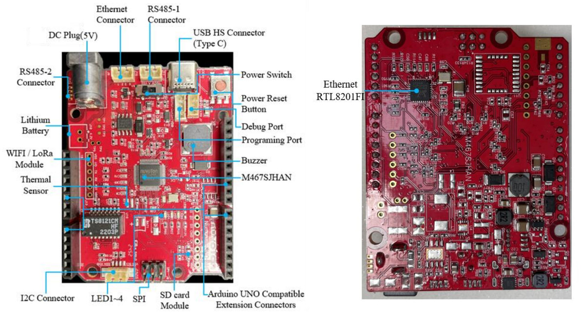
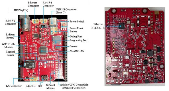
beworben wird. 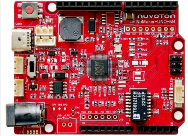 Bildquelle: Nuvoton. Der auf einem Cortex M4 basierende Chip ist unter Anderem deshalb interessant, weil er ein Ethernetinterface zur Verfügung stellt. Der im Allgemeinen gut informierte Branchennewsdienst bietet hierzu die in der Abbildung gezeigte
.jpg) Bildquelle: https://www.cnx-software.com/2025/07/14/industrial-iot-board-based-on-numicro-m467-ethernet-mcu-follows-arduino-uno-r4-form-factor/ ### PolyMaker Fiberon™ PA612-ESD - ESD-sicheres Filament für 3D-Drucker. Wer seine 3D-gedruckten Elemente in ESD-empfindlichen Umgebungen einsetzt
buffer location, and channel with prefix. G7 Reading, buffer location, and channel without prefix. SRQ M0 Disable M1 Reading overflow M2 Data store full M4 Data store half full M8 Reading done M16 Ready M32 Error EOI and bus hold- K0 Enable EOI and bus hold-off on X off K1 Disable EOI, enable bus hold-off
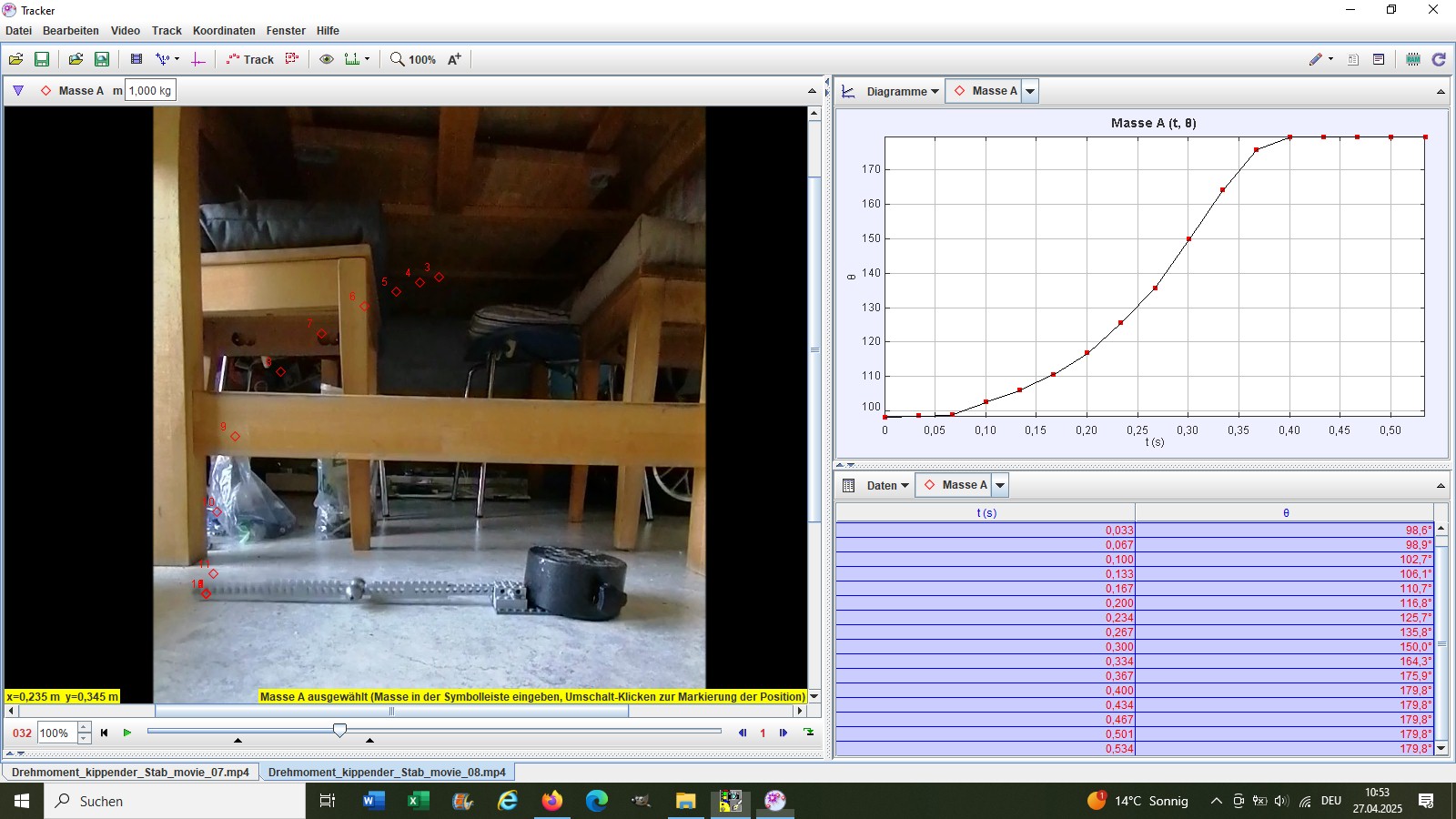
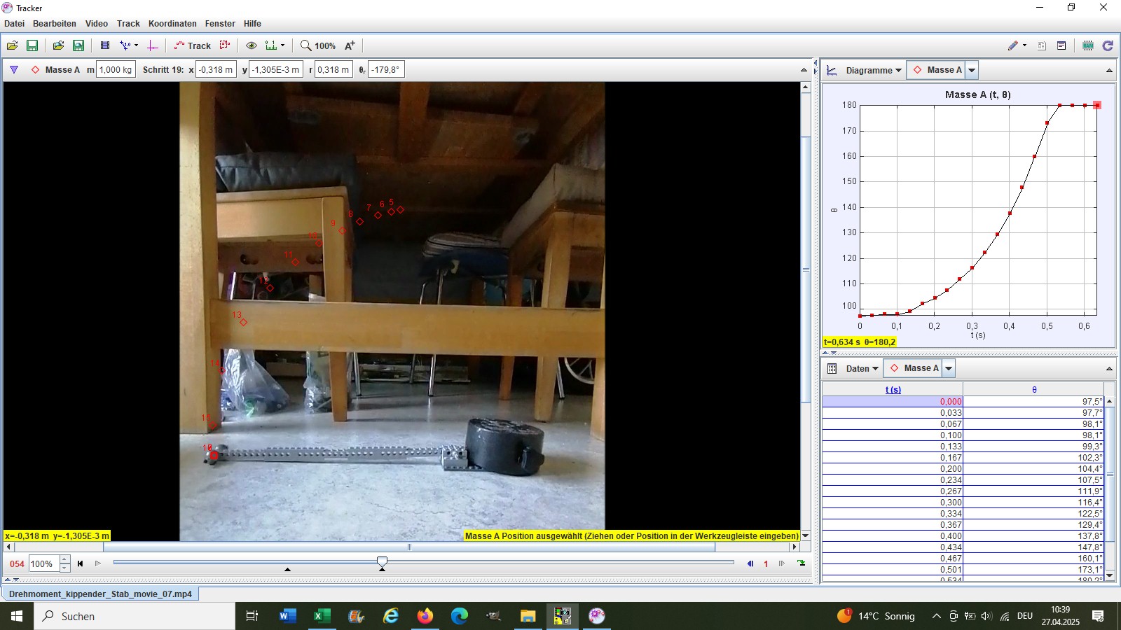
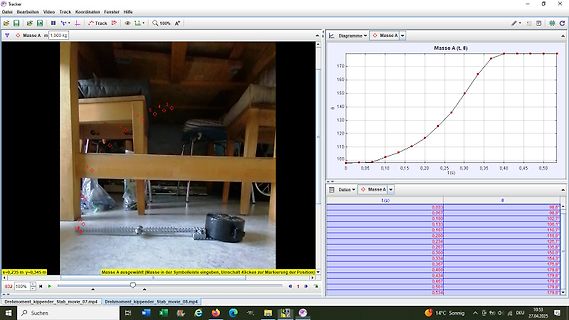
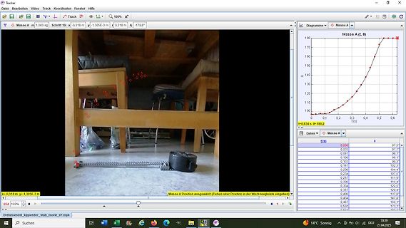
Tracker Datei Bearbeiten Video Track Koordinaten Fenster Hilfe Masse A m 1.000 kg Schritt 19: x -0,318 m y -1,305E-3 m r 0,318 m -179,8° 180 170 160 150 140 130 120 110 100 0 0,1 0,2 0,3 0,4 0,5 0,6 t (s) Masse A (t, θ) t=0,634 s θ=180,2° Daten t (s) θ Masse A Position ausgewählt
selbstklebende Folie als Frintschutz ist schon > klar, aber wie klebst du das Papier auf die Gerätefront ? 3M 467MP Transfer-Klebeband wäre eine Option. Damit hab ich früher Protoypen für Frontfolien von Industrie-Geräten gemacht
rückseitig eine selbstklebende Beschichtung haben, z.B.: https://www.bueromarkt-ag.de/laminierfolien,m-ausfuehrung:selbstklebend.html Das bedruckte Blatt erhält also beidseitig eine Folie, wobei die hintere Seite selbstklebend ist Mit meinem Ausdruck bin ich zu einer Werbeagentur gegangen und habe das
Beta Wert 25/85 K 3976 Toleranz des Betawertes 25/85 % +/- 0.5 Dissipationskonstante in Luft (still) mW/°C 2 Arbeitstemperaturbereich °C -40 bis +125 Epoxy Wärmeleitfähigkeit W/(m.K) 1,7 Abemessungen in mm 11.73 max. L = 240 mm +/- 5 mm L 5 mm +/- 1 mm 4 mm +/- 0.1 mm A A = M4 Loch 2 0 2 s e u r p e _
M 5110 Zangenmessgerät ISO 56,70 6761 Metrawatt M 6001 Oszilloskop ISO 111,00 6762 Metrawatt M 6003 Oszilloskop ISO 91,70 6763 Metrawatt M 6011 Oszilloskop ISO 111,00 6764 Metrawatt M 6014 Oszilloskop
Wallbox, und der AG hat auch mehrere 22 kW Ladesäulen. Die Dinger sind z.T. recht teuer, lohnt sich m.M.n. nur wenn man z.B. häufig da laden kann wo CEE Steckdosen vorhanden sind.
Michael M. schrieb im Beitrag #7825526: > 11kW Ladeleisung und verlege ein 5-adriges 6qmm Oh, nur 6qmm? Warum nicht gleich 16?
production protection voltage current voltage Temperature • Conform to EN 61558 115V/230V Reference V mA V °C Approval under process mA UI 39 x 8 10 VA • UL 506 approved 125/63 45037 2 x 6 2 x 833 2 x 8,2 T 50 B 125/63 45038 2 x 9 2 x 555 2 x 12,3 T 50 B 125/63 45039 2 x 12 2 x 416 2 x 16,4 T 50 B 125/
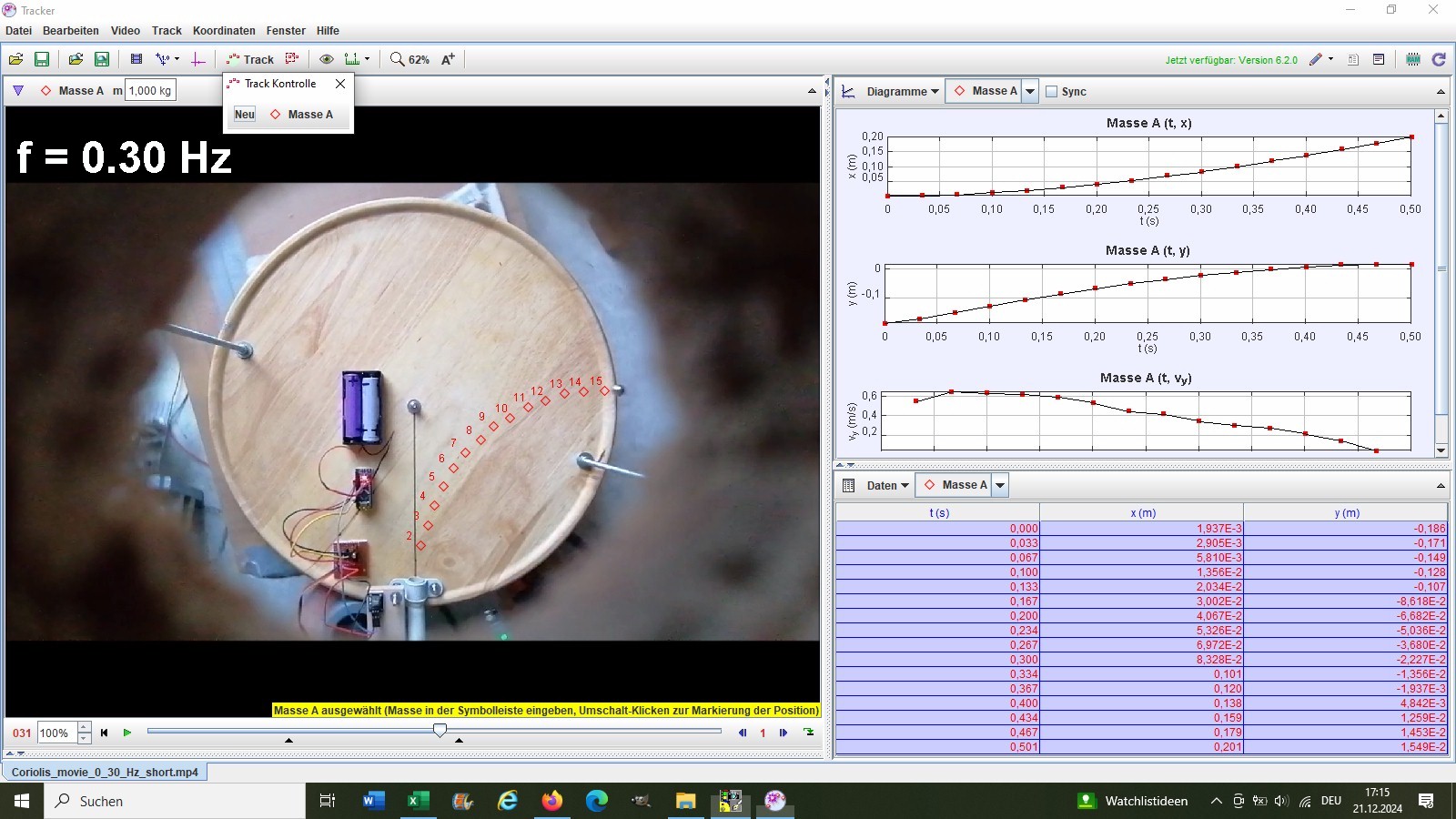
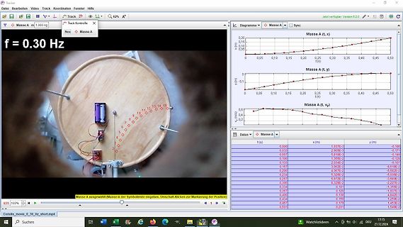
Tracker Datei Bearbeiten Video Track Koordinaten Fenster Hilfe Masse A m 1,000 kg Track Kontrolle Neu Masse A f = 0.30 Hz Masse A (t, x) x (m) t (s) Masse A (t, y) y (m) t (s) Masse A (t, vy) vy (m/s) t (s) Daten t (s) x (m) y (m) 0,000 1,937E-3 -0,186 0,033 2,905E-3 -0,171
model for varying gaps ATaylor series expansion of the aboveexpression for C(t) yields: C(t) = EA I41_-M jWeO +M t .. _ eJe(2Mtjt + ..... do do do do Thecurrent from a differential vibrating capacitor structure similar to Figure 2.7 is: A(t)M j(o M +2os)Vsej(sI +)t + dM ej(s +2M )t+ dM ej( s+3dM)t j 1 (t)= do do 22 d 4 +A dM 2jo)Me 2Mt2V + 2d V° EA d M ej(2oM)t+ dM j(4oM)t+ d do dt d do do o o From this expression, it is evident that the nonlinearities of the capacitor maps the differential-mode signal to odd harmonics of
Matthias M. schrieb im Beitrag #7777635: > Auf dem Router eine Route für Netz 192.168.1.0/24 eingetragen? Wie würde das konkret aussehen? Sollte das hier sein oder? 192.168.1.0/24 dev enp1s0 proto kernel
Mario M. schrieb im Beitrag #7777785: > Oder Du richtest auf Rechner 2 die > Internetverbindungsfreigabe ein, dann muss kein weiteres Gerät angefasst > werden. Dahinter steckt NAT, was im angefragten Szenario
Seitenwandprofil 2 HE Seitenwandprofil 3 HE A 19.5 A 19.5 . . . 4 8 7 5 2 5 Z 2 1 9 . 9 1 1 9 4 Z Y 3 15 M4 N x 15 = B ø 8.5 3 15 M4 Y N x 15 = B Y Z 4 4 ø 8.5 M ø 4.6 Y Z 4 4 M ø 4.6 02004057 02004058 Seitenwandprofil 4 HE Seitenwandprofil 6 HE A 19.5 A 19.5 5 2 1 9. 4 1 1 9 4 4 7 6 4 9 4 1 1 1 9 Z 6 2 . . 95 3 2 9 4 1 1 Z 3 15 M4 Y N x 15 = B ø 8.5 Y 3 15 M4 Y Z N x 15 = B . ø 8.5 4 4 Y Z ø 4.6 M . 4 4 ø 4.6 M 02004059 02004060 Maßtabelle Für Gehäusetiefe Einbautiefe max. Abmessungen mm mm A in mm B in mm 271 250 231 15 × 15

 Bild
Bild
 Bild
Bild
 Bild
Bild
 Bild
Bild
 Bild
Bild
 Bild
Bild

 Bild
Bild