-
Datei
3-Port_Sinus-Demo.c
// Software-PWM by PoWl - 23.10.08 // webmaster@the-powl.de // ATmega8 @ 8Mhz #include <avr/io.h> #include <avr/interrupt.h> #include <util/delay.h> #include <stdbool.h> // Sinustabelle für Demo const uint8_t sinetable[] = { 128, 131, 134, 137, 140, 143, 146, 149, 152, 155, 158, 162, 165, 167, 170, 173, 176, 179, 182, 185, 188, 190, 193, 196, 198, 201, 203, 206, 208, 211, 213, 215, 218, 220, 222, 224, 226, 228, 230, 232, 234, 235, 237, 238, 240, 241, 243, 244, 245, 246, 248, 249, 250, 250, 251, 252, 253, 253, 254, 254, 254, 255, 255, 255, 255, 255, 255, 255, 254, 254, 254, 253, 253, 252, 251,
in „8-Bit Software PWM für mehr als 8 Kanäle“ · Projekte & Code ·
-
Datei
3-Port_Sinus-Demo.c
// Software-PWM by PoWl - 25.10.08 // webmaster@the-powl.de // ATmega8 @ 8Mhz #include <avr/io.h> #include <avr/interrupt.h> #include <util/delay.h> #include <stdbool.h> // Sinustabelle für Demo const uint8_t sinetable[] = { 128, 131, 134, 137, 140, 143, 146, 149, 152, 155, 158, 162, 165, 167, 170, 173, 176, 179, 182, 185, 188, 190, 193, 196, 198, 201, 203, 206, 208, 211, 213, 215, 218, 220, 222, 224, 226, 228, 230, 232, 234, 235, 237, 238, 240, 241, 243, 244, 245, 246, 248, 249, 250, 250, 251, 252, 253, 253, 254, 254, 254, 255, 255, 255, 255, 255, 255, 255, 254, 254, 254, 253, 253, 252, 251,
in „Software-PWM stockt bei unpassender Updatefrequenz“ · Mikrocontroller und Digitale Elektronik ·
-
Datei
Sd2PinMap.h
pin_map_t digitalPinMap[] = { {&DDRE, &PINE, &PORTE, 0}, // E0 0 {&DDRE, &PINE, &PORTE, 1}, // E1 1 {&DDRE, &PINE, &PORTE, 4}, // E4 2 {&DDRE, &PINE, &PORTE, 5}, // E5 3 {&DDRG, &PING, &PORTG, 5}, // G5
in „SD Karte an AVR 328 Arduino UNO welche Pins ?“ · Mikrocontroller und Digitale Elektronik ·
-
 Bild
Bild
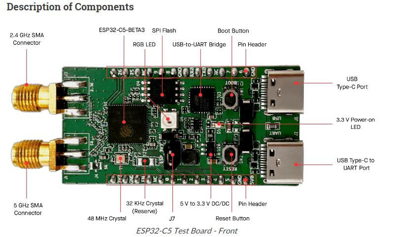
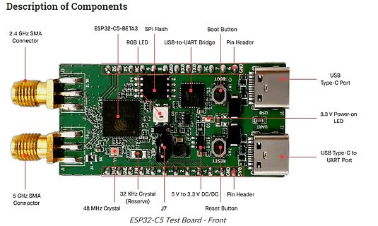
Beschriftete ESP32-C5 Testplatine
Description of Components 2.4 GHz SMA Connector ESP32-C5-BETA3 SPI Flash Boot Button RGB LED USB-to-UART Bridge Pin Header 5 GHz SMA Connector 32 KHz Crystal (Reserve) 5 V to 3.3 V DC/DC Pin Header 48 MHz Crystal J7 Reset Button USB Type-C Port 3.3 V Power-on LED USB Type-C to UART Port ESP32-C5 Test Board - Front
in „Devboard zu ESP32-C5 leakt, Orange Pi-Entwicklersymposion und neue RISC/V-Mikrocontroller“ · Mikrocontroller und Digitale Elektronik · · Platinenfotos
-
Datei
pins.h
NOK_BL 11 // D12(MISO) PB4 // D13(SCK) PB5 (LED) // ANALOG // A0 (ADC0) PC0 // A1 (ADC1) PC1 // A2 (ADC2) PC2 // A3 (ADC3) PC3 // ----------------- I2C ----------------- // A4 (ADC4/SDAglb) PC4 #define PIN_SDA 4 //PC4 -> A4 // A5 (ADC5/SCLgrn
in „ATmega328P mit mehr Pins“ · Mikrocontroller und Digitale Elektronik ·
-
Datei
Test5.c
// //Digital Ausgänge zuweisen //////////////////////////////////////////////////////////////// //Port zuweisen------------------------------------ #define R1_Aussenbeleuchtung PORTC #define R2_Regensensor PORTC #define R3_Helligkeitssensor PORTC #define R4_Sicherheitsstop PORTC //TWI PORT C4 & C5 /*
in „MyAVR Port Expander Ansteuerung“ · Mikrocontroller und Digitale Elektronik ·
-
Datei
encoder5.c
AUSGANG_PORT &= ~(SD2IEC); // SD2IEC-PIN = LO _delay_ms(DELAY_RESET); // Warten AUSGANG_DDR &= ~(SD2IEC); // SD2IEC-PIN = Eingang } // C64 und SD2IEC Reset durchführen // ----------------------------------------------------------------------- void reset_all() { AUSGANG_DDR |= (C64); // C64-PIN = Ausgang AUSGANG_PORT &= ~(C64); // C64-PIN = LO AUSGANG_DDR |= (SD2IEC); // SD2IEC-PIN = Ausgang AUSGANG_PORT &= ~(SD2IEC); // SD2IEC-PIN = LO _delay_ms(DELAY_RESET); // Warten AUSGANG_DDR
in „2 Timer parallel laufen lassen“ · Mikrocontroller und Digitale Elektronik ·
-
PDF
AT90PWM2_2B_3_3B__2_.pdf
. Port C is not available on 24 pins package. Port C also serves the functions of special features of the AT90PWM2/2B/3/3B as listed on page 72. 8 AT90PWM2/3/2B/3B 4317I–AVR–01/08 AT90PWM2/3/2B/3B 4.2.5 Port
in „Interrupt bem Flankenwechsel beim AVR“ · Mikrocontroller und Digitale Elektronik ·
-
Datei
Port_IO.c
#include <avr/io.h> #define LCD_PORT PORTC /* hier Port festlegen */ #define CS_PIN PIN0 /* hier LCD Leitungen festlegen */ #define RESET_PIN PIN1 #define RS_PIN PIN2 #define WR_PIN PIN3 #define RD_PIN PIN4 /* hier Macro fuer jede Leitung low/high */ #define CS_LOW LCD_PORT &= ~(1<<CS_PIN); //sbit _CS = P3^4; #define CS_HIGH LCD_PORT |= (1<<CS_PIN); #define RESET_LOW LCD_PORT &= ~(1<<RESET_PIN); //sbit _RES = P3^5; #define RESET_HIGH LCD_PORT |= (1<<RESET_PIN); #define RS_LOW LCD_PORT &= ~(1<<RS_PIN); //sbit _RS = P3^6; #define RS_HIGH LCD_PORT |= (1<<RS_PIN); #define WR_LOW LCD_PORT &= ~(1<<WR_PIN
in „Benörige Hilfe bei Grafikdisplay LM240120“ · Mikrocontroller und Digitale Elektronik ·
-
Datei
Pin.h
return PIND & (1 << PD##n); }; \ int8_t isLow() const { return !(PIND & (1 << PD##n)); }; \ } class PortA { public: PinA(0); PinA(1); PinA(2); PinA(3); PinA(4); PinA(5); PinA(6); PinA(7); }; class PortB { public: PinB(0); PinB(1); PinB(2); PinB(3); PinB(4); PinB(5); PinB(6); PinB(7); }; class PortC { public: PinC(0); PinC(1); PinC(2); PinC(3); PinC(4); PinC(5); PinC(6); PinC(7); }; class PortD { public: PinD(0); PinD(1); PinD(2); PinD(3); PinD(4); PinD(5); PinD(6); PinD(7); }; }; #endif
in „AVR und C++ - ein Versuch“ · Mikrocontroller und Digitale Elektronik ·
-
PDF
AVRDUDE-doc-5.5.pdf
. 5. The Windows directory. 6. The directories that are listed in the PATH environment variable. A.2.3 Port Names A.2.3.1 Serial Ports When you select a serial port (i.e. when using an STK500) use the Windows
in „USB-ISP PRogrammer unter Ubuntu“ · PC Hard- und Software ·
-
Datei
LPH8731-3C.c
,LCD_PORT_CLK,LCD_PIN_CLK,6); SPI_BIT(dta,6,LCD_PORT_DATA,LCD_PIN_DATA,LCD_PORT_CLK,LCD_PIN_CLK,5); SPI_BIT(dta,5,LCD_PORT_DATA,LCD_PIN_DATA,LCD_PORT_CLK,LCD_PIN_CLK,4); SPI_BIT(dta,4,LCD_PORT_DATA,LCD_PIN_DATA,LCD_PORT_CLK,LCD_PIN_CLK,3); SPI_BIT(dta,3,LCD_PORT_DATA,LCD_PIN_DATA,LCD_PORT_CLK,LCD_PIN_CLK,2); SPI_BIT(dta,2,LCD_PORT_DATA,LCD_PIN_DATA,LCD_PORT_CLK,LCD_PIN_CLK,1); SPI_BIT(dta,1,LCD_PORT_DATA,LCD_PIN_DATA
in „LCD LPH8731-3C aus Siemens-Handys, Treiber“ · Mikrocontroller und Digitale Elektronik ·
-
Datei
pins_arduino.h
PA , // Digital31 ** PA 7 ** DIP 33 ** USABLE }; const uint8_t PROGMEM digital_pin_to_bit_mask_PGM[] = { _BV(0), /* 0, port D BV = BitvValue, _BV(a) entspricht (1 << a) */ _BV(1), _BV(2), _BV(3), _BV(4), _BV(5), _BV(6), _BV(7), _BV(0), /* 8, port B */ _BV(1), _BV(2), _BV(3), _BV(4), _BV(5), _BV(6), _BV(7), _BV(0), /* 16, port C */ _BV(1), _BV(2), _BV(3), _BV(4), _BV(5), _BV(6), _BV(7), _BV(0), /* 24, port A */ _BV(1), _BV(2), _BV(3), _BV(4), _BV(5), _BV(6), _BV(7), }; const uint8_t PROGMEM
in „Atmega32 (16PU) mit Arduino IDE 1.0 ?“ · Mikrocontroller und Digitale Elektronik ·
-
PDF
970DE3U3S3.pdf
(PORT 2), Black) 38 Clear CMOS Jumper (CLRCMOS1) 12 1.4 I/O Panel 1 2 3 4 5 10 9 8 7 6 1 PS/2 Mouse Port (Green) 6 USB 2.0 Ports (USB01) * 2 LAN RJ-45 Port 7 USB 3.0 Port (USB01) 3 Line In (Light Blue) 8
-
Datei
IoPort.h
bei 3 struct {unsigned b50:5, b553:3;} _AP_; // 5erBits, beginnen bei 0 struct {unsigned b501:1, b51:5, b562:2;} _AP_; // 5erBits, beginnen bei 1 struct {unsigned b502:2, b52:5, b571:1;} _AP_; // 5erBits, beginnen bei 2 struct {unsigned b503:3, b53:5;} _AP_; // 5erBits, beginnen bei 3 struct {unsigned b60:6, b662:2;} _AP_; // 6erBits, beginnen bei 0 struct {unsigned b601:1, b61:6, b671:1;} _AP_; // 6erBits, beginnen
in „Präprozessor“ · Mikrocontroller und Digitale Elektronik ·
-
Datei
IoPort.h
bei 3 struct {unsigned b50:5, b553:3;} _AP_; // 5erBits, beginnen bei 0 struct {unsigned b501:1, b51:5, b562:2;} _AP_; // 5erBits, beginnen bei 1 struct {unsigned b502:2, b52:5, b571:1;} _AP_; // 5erBits, beginnen bei 2 struct {unsigned b503:3, b53:5;} _AP_; // 5erBits, beginnen bei 3 struct {unsigned b60:6, b662:2;} _AP_; // 6erBits, beginnen bei 0 struct {unsigned b601:1, b61:6, b671:1;} _AP_; // 6erBits, beginnen
in „Data-Direction-Adresse immer eine Adresse höher als Port-Ausgabeadresse?“ · Mikrocontroller und Digitale Elektronik ·
-
PDF
test_40pin.pdf
Port A Port A Port B Port B 8 1 3 9 S S S S 1 2 3 4 5 6 7 8 9 0 1 2 3 4 5 6 7 8 9 0 1 2 3 4 5 6 7 8 9 0 1 2 3 4 5 6 7 8 9 0 1 1 1 1 5 + IC1 2 3 1 1 k 3 1 4 2 R 1 VDD MCLR#/THV 40 S1 2 PGD/RB7 39 3 RA0/AN0 PGC/RB6 38 4 RA1/AN1 RB5 37 5 4 3 2 1 5 RA2/AN2 RB4 36 S 6 RA3/AN3 PGM/RB3 35 GND IC 7 RA4/T0CKI RB2 34 0 8 RE0/RD#/AN5 INT/RB0 33 8 9 RE1/WR#/AN6 C6 15pF 1 ST 10 RE2/CS#/AN7 PSP7/RD7 30 1 2 Q C PSP6/RD6 29 3 4 13 OSC1/CLKIN PSP5/RD5 28 5 6 14 OSC2/CLKOUT PSP4/RD4 27 C8 15pF 15 RC0/T1OSO RX/RC7 26 SV2 16 RC1/T1OSI TX/RC6 25 17 RC2/CCP1 SDO/RC5 24 18 RC3/SCK SDI/RC4 23 19 RD0/PSP0 RD3/PSP3 22 20
in „PIC Assemblerprogramm- Problem“ · Mikrocontroller und Digitale Elektronik ·
-
Datei
servo2.c
[2] = PD2; servo_pin[3] = PD3; servo_pin[4] = PD4; servo_pin[5] = PD5; servo_pin[6] = PD6; servo_pin[7] = PD7; #endif SERVO_0to1_DDR |= (1 << servo_pin[0]) | (1 << servo_pin[1]); #ifndef POLLIN SERVO_2to7_DDR |= (1 << servo_pin[2]) | (1 << servo_pin[3]) | (1 << servo_pin[4]) | (1 << servo_pin[5]) | (1 << servo_pin[6]) | (1 << servo_pin[7]); #endif #if defined(__AVR_ATmega48__) ||defined(__AVR_ATmega88__) // 8Bit-Timer initialisieren
in „Servo dreht nur 90Grad“ · Mikrocontroller und Digitale Elektronik ·
-
Datei
lcd2.c
<LCD_E_PIN); // Enable auf 1 setzen LCD_DATA_PORT = 0x30; //Set PA4 und PA5 high LCD_CTRL_PORT &= ~(1<<LCD_E_PIN); // Enable auf 0 setzen _delay_ms(2000); //Function Set 3 LCD_CTRL_PORT |= (1<<LCD_E_PIN); // Enable auf 1 setzen LCD_DATA_PORT = 0x30; //Set PA4 und PA5 high LCD_CTRL_PORT &= ~(1<<LCD_E_PIN); // Enable auf 0 setzen _delay_ms(2000); out_stat_reg(0x3c); //set Display lines out_stat_reg(0x08); //Display off out_stat_reg(0x01);
in „Ansteuern eines LCD über ATmega16“ · Mikrocontroller und Digitale Elektronik ·
-
Datei
TLC5940_3.c
XLAT_DDR DDRB #define XLAT_PORT PORTB #define XLAT_PIN PB2 #define DCPRG_DDR DDRB #define DCPRG_PORT PORTB #define DCPRG_PIN PB4 #define S_IN_DDR DDRB #define S_IN_PORT PORTB #define S_IN_PIN PB5 #define S_OUT_DDR DDRB #define S_OUT_PORT
in „16 TLC5940 an ca. 80RGB LED´s via timer und spi angesprochen“ · Analoge Elektronik und Schaltungstechnik ·
-
Datei
iotn5.h
_SFR_IO8(0x3C) #define CCP0 0 #define CCP1 1 #define CCP2 2 #define CCP3 3 #define CCP4 4 #define CCP5 5 #define CCP6 6 #define CCP7 7 /* Interrupt vectors */ /* Vector 0 is the reset vector */ #define INT0_vect_num
in „direkt in ein Register des Tiny5 schreiben“ · Mikrocontroller und Digitale Elektronik ·
-
Datei
rc5decoder.c
/************************************************************************/ /* */ /* RC5 Remote Receiver */ /* */ /* Author: Peter Dannegger */ /* danni@specs.de */ /* */ /* Modified by Malte Marwedel 2014-10-01: */ /* Version for XMEGA timer, tested with internal 2MHz RC. */ /* Stopping the timer and using the pin isr for wakeup */ /* allows stopping the resonator while no signal gets */ /* received. This saves power. Note that only pin two of */ /* each port has full ISR port while not clocked. */ /* */ /************************************************************************/ #include <avr/io.h
-
Datei
m8a_Pin-Test2.c
/* * ATmega8A Pin Cycling Test * Version 2: Array in RAM * * Cycles through PB0–PB5, PC0–PC5, PD0–PD7. * Every 200 ms: one pin is driven low, then returned to input with pull-up, * then the next pin is selected. * * Same as version 1, but lookup table loaded to RAM on startup. */ #include <avr/io.h> #include <avr/interrupt.h> #include <avr/sleep.h> #include <stdint.h> #include <util/delay.h> typedef struct { uint16_t ddrAddr; uint16_t portAddr; uint8_t mask; } PinDesc; // --- Array of test pins in flash (PROGMEM) --- // Use addresses cast to uint16_t PinDesc testPins[] = { { (uint16_t)&DDRB, (
in „Atmega8A: loop über Ports/Pins funktioniert nicht“ · Mikrocontroller und Digitale Elektronik ·
-
PDF
V2Pro_Board_User_Guide_2_2.pdf
Pro FPGA JTAG Port XC2VP4 Differential (FG456) Clock Input Parallel Cable IV (SMA) JTAG Port CPU Debug Port RS232 Port CPU TRACE Port LCD Panel User 1.5V 2.5V 3.3V 2.5V Switches Regulator Regulator Regulator Rocket I/
-
 Bild
Bild
Ausschnitt aus einem Lattice MachXO2 Datenblatt
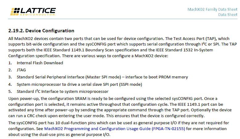
are various ways to configure a MachXO2 device: 1. Internal Flash Download 2. JTAG 3. Standard Serial Peripheral Interface (Master SPI mode) – interface to boot PROM memory 4. System microprocessor to drive a serial slave SPI port (SSPI mode) 5. Standard I2C Interface to system microprocessor Upon power-up, the configuration SRAM is ready to be configured using the selected sysCONFIG port. Once a configuration port is selected, it remains active
in „JTAG boundary scan komisches verhalten“ · FPGA, VHDL & Co. · · Screenshots
-
Datei
Xmega_test_5_debounce.c
/************************************************************************/ /* */ /* Debouncing 8 Keys */ /* Sampling 4 Times */ /* With Repeat Function */ /* */ /* Author: Peter Dannegger */ /* danni@specs.de */ /* */ /************************************************************************/ #include <stdint.h> #include <avr/io.h> #include <avr/interrupt.h> #ifndef F_CPU #define F_CPU 32000000 // processor clock frequency #warning kein F_CPU definiert #endif #define KEY_DDR PORTA_DIR #define KEY_PORT PORTA #define KEY_PIN PORTA_IN #define KEY0 0 #define KEY1 1 #define KEY2 2 #define ALL_KEYS (1
in „Peter Dannegger's Debounce Routine für Xmega“ · Mikrocontroller und Digitale Elektronik ·
-
PDF
_MatchPort_UG.pdf
would connect to 129.1.2.3 and port 7.) You may also use a different ending for the connection string. For example, C50.1/23 would connect you to 129.1.50.1 and port 23. Table 5-8. Manual Connection Address Example Command String Result if remote IP is 129.1.2.3 and remote port is 1234 C121.2.4.5/1 Complete override; connection is started with host 121.2.4.5, port 1 C5 Connects to 129.1.2.5, port 1234 C28.10/12 Connects to 129.1.28.10, port 12 C0.0.0.0/0 Enters
in „Matchport b/g mit PC verbinden“ · PC Hard- und Software ·
-
Datei
Xmega_test_5_debounce.c
/************************************************************************/ /* */ /* Debouncing 8 Keys */ /* Sampling 4 Times */ /* With Repeat Function */ /* */ /* Author: Peter Dannegger */ /* danni@specs.de */ /* */ /************************************************************************/ #include <stdint.h> #include <avr/io.h> #include <avr/interrupt.h> #ifndef F_CPU #define F_CPU 32000000 // processor clock frequency #warning kein F_CPU definiert #endif #define KEY_DDR PORTA_DIR #define KEY_PORT PORTA #define KEY_PIN PORTA_IN #define KEY0 0 #define KEY1 1 #define KEY2 2 #define ALL_KEYS (1
in „Peter Dannegger's Debounce Routine für Xmega“ · Mikrocontroller und Digitale Elektronik ·
-
Datei
Temperaturausgabe5.txt
UBR11 = 0x00; // UMCTL1 = 0x4A; // Modulation UCTL1 &= ~SWRST; // Initialize USART state machine P2SEL|=0x00; // Port2 als input output benutzten P1DIR|=0xFF; // Port1 sind die 8 LEDs P2DIR|=0xFF; //Port2 sind die Latschsignale für 7-Segment decoder P3SEL |= 0x0a; // Assign I2C pins to module P3OUT |= 0x05; //am Port3 Pin 1+3 auf High setzen (Latch Pins) P1OUT = 0x00; U0CTL |= I2C + SYNC; // Switch USART0 to I2C mode U0CTL &= ~I2CEN; // Recommended I2C init procedure I2CTCTL = I2CSSEL_2; // SMCLK I2CPSC = 0x06;
in „LM75 mit MSP430F1611“ · Mikrocontroller und Digitale Elektronik ·
-
Datei
m8a_Pin-Test2.c
/* * ATmega8A Pin Cycling Test * Version 2: Array in RAM * * Cycles through PB0–PB5, PC0–PC5, PD0–PD7. * Every 200 ms: one pin is driven low, then returned to input with pull-up, * then the next pin is selected. * * Same as version 1, but lookup table loaded to RAM on startup. */ #include <avr/io.h> #include <avr/interrupt.h> #include <avr/sleep.h> #include <stdint.h> #ifndef F_CPU # define F_CPU 1E6 #endif #include <util/delay.h> typedef struct { volatile uint8_t *ddrAddr; volatile uint8_t *portAddr; uint8_t mask; } PinDesc; // --- Array of test pins in flash (PROGMEM) --- // Use addresses cast
in „Atmega8A: loop über Ports/Pins funktioniert nicht“ · Mikrocontroller und Digitale Elektronik ·
-
PDF
MatchPort_IntegrationGuide.pdf
-CP8 Low Level Output Current 4.4 7.1 8.5 mA @VOL 0.4V TXDx, RTSx IOH -3.2 -6.4 -10.0 mA High Level Output Current @ VOH 2.4V CP1-CP8 IOH -3.2 -6.4 -10.0 mA High Level Output Current @ VOH 2.4V * For UART and CP pins MatchPort b/g™ Integration
in „Wlan Modul Spannung“ · Mikrocontroller und Digitale Elektronik ·
-
Datei
ATB_Menue_2.c
/* ATB_Menue_2.c Created: 13.03.2016 17:54:24 Author : AS */ // ori Teile P30 und P64 und D2 + NT // P64 Tastenboard Belegung Buchsenleiste // Pin 1-frei Pin 2-Servo Pin 3-LED // Pin 4-T1 Pin 5-T2 Pin 6-T3 // Pin 7-T4 Pin 8-T5 // P30 Board 1 Prozessor Port A-Buchsenleiste // PA 0-Pin 1-frei PA 1-Pin 2-Servo // PA 2-Pin 3-LED PA 3-Pin 4-T1 // PA 4-Pin 5-T2 PA 5-Pin 6-T3 // PA 6-Pin 7-T4 PA 7-Pin 8-T5 // T1-hoch, T3-enter
in „Einfaches Menue mit I2C Bus in C“ · Mikrocontroller und Digitale Elektronik ·
-
Datei
93AA86C_SPI_3.c
Lesen erfordert einen extra Takt, der bei abgeschaltettem SPI gegeben werden muß. Das EEPROM 93AA46C erfordert anderen Code, geht mit diesem nicht direkt. EPROM am Mega162 CS, Pin1 PC0, Pin21 <<<<<-----<<<<--- CLK, Pin2 PB7, Pin8 Din, Pin3 MOSI, PB5, Pin6 Dout, Pin4 MISO, PB6, Pin7 Pin5 = GND ORG immer
in „Ansteuerung EEPROM 93AA96C funktioniert nicht richtig“ · Mikrocontroller und Digitale Elektronik ·
-
Datei
LPH8731-3C.h
| ------------------------------------ | | | ------------------------------------------------ LCD pins (1,2,3,4,5 -> CS,RES,RS,CLK,DATA ) mapped to ATMega (in software SPI mode) 1 CS - D5 2 RES - D6 3 RS - D7 4 CLK - B0 ( CLK/DATA must be connected to the same port (!) ) 5 DATA - B1 other pins of module
in „LCD LPH8731-3C aus Siemens-Handys, Treiber“ · Mikrocontroller und Digitale Elektronik ·
-
Datei
dogm_spi_3.3V.c
, // booster off, contrast C5, set C4 0b01101001, // set voltage follower gain (5V) #endif 0b01010101, // 3,3V settings: booster off 0b01101101, // set voltage follower gain (3,3V) 0b01110100, //01110100, // set contrast C3,C2,C1
in „EA DOGM162 mit STM32 reagiert nicht mit SPI“ · Mikrocontroller und Digitale Elektronik ·
-
PDF
cyc_c5v1-1299412.pdf
array array 4 4 CLK0 PLL1 PLL2 CLK2 CLK1 (3) (2) CLK3 (3) 2 4 4 2 DPCLK0 DPCLK5 DPCLK7 DPCLK6 Notes to Figure 2–22: (1) The EP1C3 device in the 100-pin TQFP package has five DPCLK pins (DPCLK2, DPCLK3, DPCLK4, DPCLK6, and DPCLK7).
in „BMW Nightvision (FLIR PathfindIR) "Wärmebildkamera"“ · Mikrocontroller und Digitale Elektronik ·
-
PDF
BGScript_developer_guide_v3.3.pdf
_______________________________________________________________ 21 5.2.1 ADC ______________________________________________________________________ 21 5.2.2 I2C _______________________________________________________________________ 23 5.2.3 IO _______________________
in „BLE112 wer kennt sich mit dem UART aus ?“ · Mikrocontroller und Digitale Elektronik ·
-
Datei
GSM-CONTROLLER2.3.c
#define Time_isr 0x4C01 // Die Start und stop Zeit in min (max. 30min.) void ISR_T1(void); enum {Standby, Pump} state; //State-Event Definition /* EasyCODE ( 2 void enter_pin(void) */ /* EasyCODE F */ void enter_pin(void)
in „Serielle Schnittstelle?????“ · Mikrocontroller und Digitale Elektronik ·
-
Datei
93AA86C_SPI_2.c
tatsächlich diese Abfrage auf Ready/busy erfolgen. weiter siehe eeprom_1/SPI_EEPROM_Write_Read_Alphabet_8.c EPROM am Mega162 CS, Pin1 PC0, Pin21 <<<<<-----<<<<--- CLK, Pin2 PB7, Pin8 Din, Pin3 MOSI, PB5, Pin6 Dout, Pin4 MISO, PB6, Pin7 Pin5 = GND ORG immer an GND PE immer an + Pin8 +5V Table 1 - 4 8-bit modus
in „Ansteuerung EEPROM 93AA96C funktioniert nicht richtig“ · Mikrocontroller und Digitale Elektronik ·
-
PDF
ATxMEGA_128_Board_3.pdf
serielle Schnittstelle (X2) Seite 4 von 14 Datenblatt ATxMegaBoard 3 17. Juli 2011 I²C Schnittstelle Belegung Pin Gnd 1 SDA 2 SCL 3 3,3 V 4 Tabelle 5: Belegung I²C (JP4) EBI Schnittstelle Belegung Pin Pin Belegung 3,3V 1 2 3,3
-
Datei
MP3Example.c
ISR(USARTF0_RXC_vect) { VS_Buffer_write(VSBuffer, USART.DATA); } void init_USART() { PORTF.DIRSET = PIN3_bm; // Pin3 = (TXD0) PORTF.DIRCLR = PIN2_bm; // Pin2 = (RXD0) USART.CTRLC = USART_CHSIZE_8BIT_gc | USART_PMODE_DISABLED_gc; USART.CTRLA = (USART.CTRLA & ~USART_RXCINTLVL_gm) | USART_RXCINTLVL_HI_gc
in „FIFO lösung für 1MBaud zu 0,32MBaud Problem“ · Mikrocontroller und Digitale Elektronik ·
-
Datei
i2c-slave.c
__) | \ defined(__AVR_ATmega649__) | defined(__AVR_ATmega6490__) #define USI_DDR DDRE #define USI_PORT PORTE #define USI_PIN PINE #define USI_SDA PE5 #define USI_SCL PE4 #elif defined(__AVR_ATmega169__) #define USI_DDR DDRE #define USI_PORT PORTE #define USI_PIN PINE #define USI_SDA PE5 #define USI_SCL
in „LCD ueber i2c mit ATMega88PA“ · Mikrocontroller und Digitale Elektronik ·
-
Datei
PPS5330_V1.5.c
PD5 #define SOFT_SPI_CLK_BIT PD6 #define SOFT_SPI_MISO_PIN PD5 #define ADC_AD0 PC0 // (A0) #define ADC_AD1 PC1 // (A1) #define ADC_AD2 PC2 // (A2) #define ADC_ADW PD2 // (INT0) #define Standby PC4 // (A5
in „PPS5330 Labor-Netzteil hack“ · Mikrocontroller und Digitale Elektronik ·
-
PDF
OV528_DS_1.3.pdf
16 D ATASHEET Pin # Name I/O Function F5 DVDD PWR Digital 3.3V power F6, DVSS GND Digital ground F7 DVDD PWR Digital 3.3V power F8 P2[0] I/O Internal MC port 2 bit 0 G1 Y[7] I Camera Y/C /C input bit 7 b r G2 PLL_SEL
-
Datei
r5f2136cy.h
PORT PORT_0 #define ADC_CH1_PIN 6 #define ADC_CH1_NUM 0x01 #define ADC_CH1_REG AD1 #define ADC_CH2_PORT PORT_0 #define ADC_CH2_PIN 5 #define ADC_CH2_NUM 0x02 #define ADC_CH2_REG AD2 #define ADC_CH3_PORT
in „Universelle Mikrocontroller Toolchain (Linux)“ · Mikrocontroller und Digitale Elektronik ·
-
PDF
ATxMEGA_128_Board_2.pdf
ADC DAC ATxMEGA Block Diagramm Abbildung 1 Block Diagramm des ATxMEGA Stiftleistenbelegungen I/O Ports (Port A, B, C, D, F) Belegung Pin Pin Belegung PORTx0 1 2 PORTx1 PORTx2 3 4 PORTx3 PORTx4 5 6 PORTx5 PORTx6 7 8 PORTx7 3,3 V 9 10 Gnd Tabelle 1: Belegung PORTx Hinweis: Das „x“ dient als Platzhalter
-
Datei
r5f2136cy.inc
, PORT_1 .equ UART0_RXD_PIN , 5 .equ UART0_TXD_PIN , 4 .equ UART2 , 1 .equ UART2_PORT , PORT_6 .equ UART2_RXD_PIN , 4 .equ UART2_TXD_PIN , 3 .equ EXTINT0 , 1 .equ EINT0_PORT , PORT_4 .equ EINT0_PIN , 5 .equ
in „Universelle Mikrocontroller Toolchain (Linux)“ · Mikrocontroller und Digitale Elektronik ·
-
Datei
prog.c
edges // Pin2 Inverted: Off // Pin2 Slew Rate Limitation: Off PORTB.PIN2CTRL=PORT_OPC_TOTEM_gc | PORT_ISC_BOTHEDGES_gc; // Pin3 Output/Pull configuration: Totempole/No // Pin3 Input/Sense configuration: Sense both
in „Codevision CodeWizardAVR TWI Probleme“ · Mikrocontroller und Digitale Elektronik ·
-
PDF
PI4IOE5V9555.pdf
PI4IOE5V9555 16-Bit I2C-Bus and SMBus I/O Port with Interrupt Features Description 2 Operation Power Supply Voltage from 2.3V to 5.5V The PI4IOE5V9555 is an I C-bus I/O expander that provides 16-bit I/O
in „Schachbrettposition Erkennung“ · Mikrocontroller und Digitale Elektronik ·
-
PDF
ts3dv642.pdf
+B CEC 15 24 D2–B SEL1 16 23 D3+B 8 9 0 1 SEL2 17 1 1 2 2 22 D3–B Not to scale _ _ _ _ C D C D C H C H Pin Functions PIN TYPE DESCRIPTION NAME NO. VCC 1 Power Supply Voltage SEL1 16 I Select Input 1 SEL2 17 I Select
in „HDMI Probleme“ · Mikrocontroller und Digitale Elektronik ·