-
 Bild
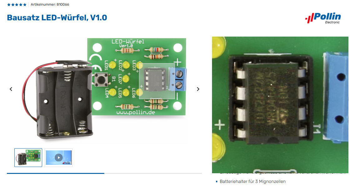
Bausatz LED-Würfel mit Leiterplatte und Batteriefach
Bausatz LED-Würfel, V1.0, Pollin Electronic, LED1 bis LED6, B1, www.pollin.de, Batteriehalter für 3 Mignonzellen
in „NE555 wird heiß“ · Mikrocontroller und Digitale Elektronik · · Platinenfotos

-
 Bild
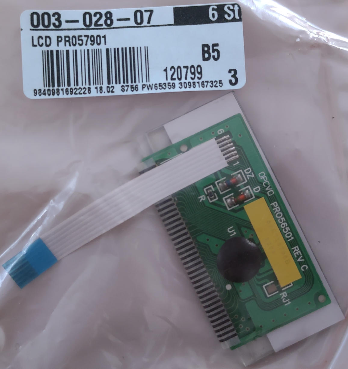
Leiterplatte mit Flexkabel und Etikett
003-028-07 6 St LCD PR057901 B5 120799 3 9840981692228 18.02 $756 PW65359 3098167325 DZ D D OPCVD PR056501 REV C U1 RJ1
in „Infos/Dtenblatt zum Pollin Display PR057901 (PRO5650 Rev.C) gesucht“ · Offtopic · · Platinenfotos

-
 Bild
Ausschnitt eines Etiketts einer digitalen Küchenwaage
007-133-03 1 St. Digitale Küchenwaage, SKWS 5 A1. weiß A3 03.08 S722 695182 4 9841457884581 PW17784 3145786074
in „Abschaltautomatik Waage überbrücken“ · Analoge Elektronik und Schaltungstechnik · · Sonstiges

-
PDF
Pollin_Fehlerbehebung.pdf
Fehlerbehebung Atmel Evaluations-Bausatz Art. Nr. 810 022 1 . Bestückungsseite: Bitte mit einem geeigneten Bohrer, an der gekennzeichneten Stelle das Lötauge anbohren, so dass keine Verbindung zur Leiterbahn besteht. 2 . Lötseite: Bitte hier die gekennzeichnete Leiterbahn auftrennen und mit Hilfe eines Brückendrahtes die eingezeichneten Verbindungen herstellen. Die mit Lötstoplack bedeckten den Verbindungsstellen, mit Hilfe eines Glasfaserstiftes oder eines feinen Schleifpapiers, freigelegt werden) Bitte beachten Sie: In der Stückliste der Montageanleitung wurden 3 . die Dioden D1 und D3 vertauscht
in „Einstieg in die programmierung“ · Mikrocontroller und Digitale Elektronik ·
-
PDF
Pollin_Board.pdf
Atmel Evaluations-Board Version 2.0 Best.Nr. 810 038 3. Auflage Pollin Electronic GmbH Tel. (08403) 920-920 www.pollin.de Stand 26.02.2007, inhouse, #web, hk Wichtiger Hinweis! Lesen Sie diese Gebrauchsanleitung, bevor Sie diesen Bausatz in Betrieb nehmen. Bewahren Sie
in „AVR: UART Pollin Board“ · Mikrocontroller und Digitale Elektronik ·
-
Datei
PollinEncoder.asm
;************************************************************************ ;* Pollin Panasonic 16348 Encoder mit 2ms Timerinterruptabfrage ;* Autor: Hannes Lux (hannes) abgeändert von (rulixa) ;*http://www.mikrocontroller.net/topic/172127#1650592 ;* OLD NEW Drehrichtung ;* 11 10 rechts
in „Hilfe zu Drehencoder-Auswertung nach Wiki“ · Mikrocontroller und Digitale Elektronik ·
-
Datei
PollinLED.c
// Temp_Doppel_LED Licht Pollin Board #define F_CPU 16000000 #include<avr/io.h> void ADC_Init (void) { uint16_t result; // "result" bezeichnet ein 16-Bit integer ADMUX = (1<<REFS0)|(1<<ADLAR); // interne Referenzspannung Vcc, Ergebnis
in „"Frischling" braucht Hilfe bei ADC“ · Mikrocontroller und Digitale Elektronik ·
-
Datei
PollinSpiel.bas
$framesize = 40 $swstack = 10 $hwstack = 30 $regfile = "ATtiny2313.dat" $crystal = 1000000 Lcd_db4 Alias Portb.0 Lcd_db5 Alias Portb.1 Lcd_db6 Alias Portb.2 Lcd_db7 Alias Portb.3 Lcd_e Alias Porta.0 Lcd_rs Alias Porta.1 Lcd_ein Alias Portd.6 Lcd_kontrast Alias Portb.4 Config Lcd_kontrast = Output Summer Alias Portd.5 Led1 Alias Portd.4 Led2 Alias Portd.3 T1 Alias Pind.0 T2 Alias Pind.1 Config Lcdmode = Port Config Timer1 = Timer , Prescale = 1 Config Lcd = 16 * 2 , Chipset = Ks077 Tccr0a = 0 Tccr0b = &B00001011 '64 Bit Prescaler 'LCD wird im 4-Bit-Modus betrieben Config Lcdbus = 4 Config Lcdpin =
in „Messgeraetchen aus Pollin Spiel bauen“ · Mikrocontroller und Digitale Elektronik ·
-
Datei
PollinLED.c
// Temp_Doppel_LED Licht Pollin Board #define F_CPU 16000000 #include<avr/io.h> #include<util/delay.h> void ADC_Init (void) { uint16_t result; // "result" bezeichnet ein 16-Bit integer ADMUX |= (1<<MUX2); // Kanal 4 lesen ADMUX |
in „"Frischling" braucht Hilfe bei ADC“ · Mikrocontroller und Digitale Elektronik ·
-
Datei
dmesg_pollin.txt
<5>Linux version 2.6.21.3PNX8550 (root@smithy) (gcc version 4.0.0 (DENX ELDK 4.0 4.0.0)) #1743 Fri Feb 11 10:49:15 OMST 2011 <4>Setting initial splash screen display mode SD (50Hz) <4>CPU revision is: 00061200 <4>Determined physical RAM map: <4> memory: 07000000 @ 00000000 (usable) <6>Initrd not found or empty - disabling initrd <7>On node 0 totalpages: 28672 <7> DMA zone: 224 pages used for memmap <7> DMA zone: 0 pages reserved <7> DMA zone: 28448 pages, LIFO batch:7 <7> Normal zone: 0 pages used for memmap <4>Built 1 zonelists. Total pages: 28448 <5>Kernel command line: console=ttyS0 stb810_display
in „Pollin - Receiver-Mainboard mit Twin DVB-[T,C] Tuner, NXP PNX8950EH“ · Mikrocontroller und Digitale Elektronik ·
-
Datei
pollin-userfserr.txt
Mount nfs root 192.168.0.3:/pollinux/nandfs... done Switch root Creating device nodes...done Set log level... Setting up /tmp... done Starting logging daemons...done Setting up network...done Mounting config fs... done done du: /config/debug/: No such file or directory done Starting command server... - done Setting up timezone... done /etc/init.d/S19network: .: 10: Can't open /config/settings.conf Loading luddite (256M_NOIP)... lud-core lud-pnx8550 phStbDspInfo done Loading pre-TM modules... fusion mmio i2c3203 i2c0105 tda1004x tda10021 tda10048 stv0297 demux dvb ak470 saa8510 tda9983 output_mode
in „Pollin - Receiver-Mainboard mit Twin DVB-[T,C] Tuner, NXP PNX8950EH“ · Mikrocontroller und Digitale Elektronik ·
-
PDF
pollin_board.PDF
Atmel Evaluations-Board Version 2.0 Best.Nr. 810 038 3. Auflage Pollin Electronic GmbH Tel. (08403) 920-920 www.pollin.de Stand 26.02.2007, inhouse, #web, hk Wichtiger Hinweis! Lesen Sie diese Gebrauchsanleitung, bevor Sie diesen Bausatz in Betrieb nehmen. Bewahren Sie
in „Atmega32 Evaluationsboard pollin mysmartusb“ · Mikrocontroller und Digitale Elektronik ·
-
PDF
pollin_board.PDF
Atmel Evaluations-Board Version 2.0 Best.Nr. 810 038 3. Auflage Pollin Electronic GmbH Tel. (08403) 920-920 www.pollin.de Stand 26.02.2007, inhouse, #web, hk Wichtiger Hinweis! Lesen Sie diese Gebrauchsanleitung, bevor Sie diesen Bausatz in Betrieb nehmen. Bewahren Sie
in „Interrupt und PortC Atmega32“ · Mikrocontroller und Digitale Elektronik ·
-
Datei
Pollin_LCD.cpp
/* * Pollin_LCD.cpp * * Created: 21.06.2014 22:30:37 * Author: Tim */ #include <avr/io.h> #include "lcd_routines.h" #include "lcd_routines.c" int main(void) { lcd_init(); lcd_string("Hallo"); while(1) { } }
in „LCD an Atmega 8“ · Mikrocontroller und Digitale Elektronik ·
-
PDF
DCF_Pollin.PDF
Umgebung in welcher brennbare Gase, Dämpfe oder Stäube vorhanden sind oder vorhanden sein können. Pollin Electronic GmbH •Tel. (08403) 920-920 • www.pollin.de Stand 04.01.2010, inhouse, #1000, hsc Bestimmungsgemäße Verwendung Das DCF-Modul DCF1 wird als Empfangsmodul für den Zeitzeichensender nähe Frankfurt
in „richtigen OP AMP auswählen“ · Analoge Elektronik und Schaltungstechnik ·
-
PDF
Bausatz_Pollin.PDF
Personenschäden führen! Eine Reparatur des Gerätes darf nur vom Elektrofachmann durchgeführt werden! Pollin Electronic GmbH • Max-Pollin-Str.1 • 85104 Pförring •Tel. (08403) 920-920 • www.pollin.de Stand 18.03.2013, #hka Bestimmungsgemäße Verwendung Der Geiger-Müller-Zähler dient nur dazu Gamma Strahlungen
in „Hochspannungserzeugung nach Pollin für Geiger-Müller-Zähler“ · Analoge Elektronik und Schaltungstechnik ·
-
PDF
Pollin_Ultraschallkapseln.pdf
Vergleich zwischen Ultraschallkapseln Ultraschall-Receiver EFR-RCB40K54 (Pollin 390 048 für 0,50 EUR am 19.05.2014) Ultraschall-Transducer RD25K2 (Pollin 390 041 für 1,25 EUR am 19.05.2014) Versuchsaufbau Sender: Rechteckgenerator mit bipolaren Timer 555 Unterschiedliche Kapseln
in „Ultraschallmikro f. Fledermäuse?“ · Analoge Elektronik und Schaltungstechnik ·
-
PDF
Pollin_Geigerzaehler.pdf
Personenschäden führen! Eine Reparatur des Gerätes darf nur vom Elektrofachmann durchgeführt werden! Pollin Electronic GmbH • Max-Pollin-Str.1 • 85104 Pförring •Tel. (08403) 920-920 • www.pollin.de Stand 18.03.2013, #hka Bestimmungsgemäße Verwendung Der Geiger-Müller-Zähler dient nur dazu Gamma Strahlungen
in „Pollin Geigerzähler Bericht“ · Mikrocontroller und Digitale Elektronik ·
-
PDF
-
PDF
Pollin_2021.pdf
Suchergebnis Name Bereich Information V.-Datum Pollin Electronic GmbH Rechnungslegung/ Jahresabschluss zum Geschäftsjahr vom 01.01.2021 04.05.2023 Pförring Finanzberichte bis zum 31.12.2021 Pollin Electronic GmbH Pförring Jahresabschluss zum Geschäftsjahr
in „Pollin ist pleite :-(“ · Offtopic ·
-
 Bild
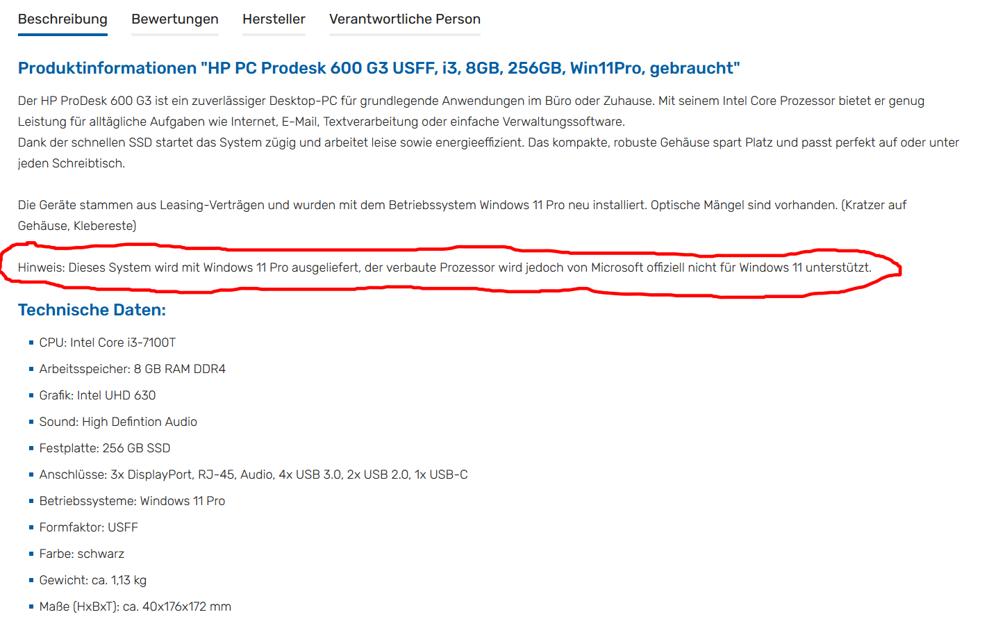
Produktbeschreibung HP ProDesk 600 G3 USFF
Beschreibung Bewertungen Hersteller Verantwortliche Person Produktinformationen "HP PC Prodesk 600 G3 USFF, i3, 8GB, 256GB, Win11Pro, gebraucht" Der HP ProDesk 600 G3 ist ein zuverlässiger Desktop-PC für grundlegende Anwendungen im Büro oder Zuhause. Mit seinem Intel Core Prozessor bietet er grundlegende Leistung für alltägliche Aufgaben wie Internet, E-Mail, Textverarbeitung oder einfache Verwaltungssoftware. Danke der schnellen SSD startet das System zügig und arbeitet leise sowie energieeffizient. Das kompakte, robuste Gehäuse spart Platz und passt perfekt auf oder unter einen Schreibtisch. Die
in „Asus H170 pro mit Core I7-7700 - kein Bild/startet nicht“ · PC Hard- und Software · · Screenshots

-
 Bild
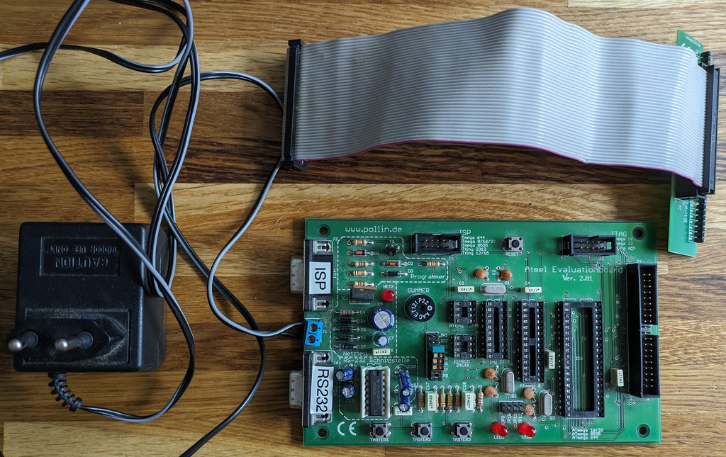
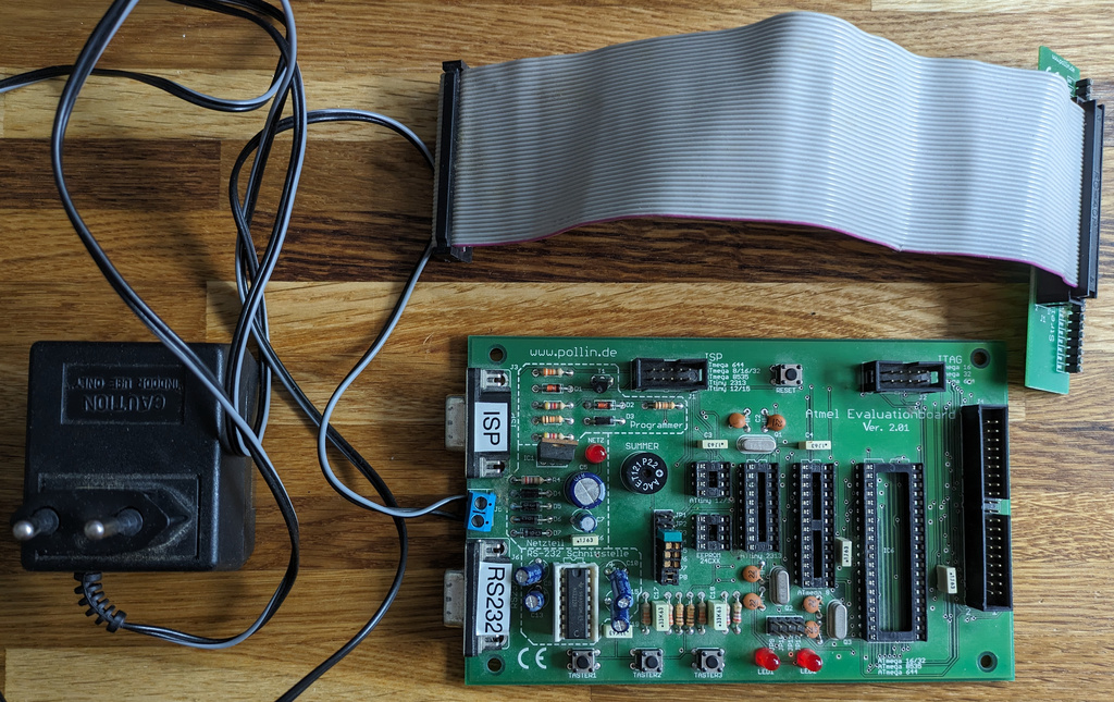
Atmel Evaluation Board mit Netzteil und Flachbandkabel
www.pollin.de ISP ISP RS232 Atmel Evaluation Board Ver. 2.01 SUMMER CE
in „[V] Diverse Evaluation Boards & Co.“ · Markt · · Platinenfotos

-
 Bild
Atmel Evaluation Board mit Netzteil und Flachbandkabel
www.pollin.de ISP ISP RS232 Atmel Evaluation Board Ver. 2.01 SUMMER CE
in „[V] Diverse Evaluation Boards & Co.“ · Markt · · Platinenfotos

-
 Bild
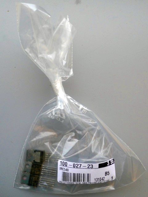
Elektronikbauteil in Plastiktüte mit Etikett
100-027-23 IRC540 3 St. B5 131042 1 9841277406932 13 02 9848 PW22991 3127737489
in „Transistoren - Die-Bilder“ · Analoge Elektronik und Schaltungstechnik · · Fotos

-
 Bild
Parkplatz vor einem Firmengebäude mit Autos
Pollin KEH JR 318 NF AV 461
in „Pollin kaputt?“ · Offtopic · · Fotos

-
Datei
PollinBascomTest.bas
' Fuer Pollin Display 16080 mit Touch ' allu 9/2009 $regfile = "m32def.DAT" $crystal = 8000000 $baud = 19200 $hwstack = 64 $swstack = 256 $framesize = 84 'PortPins zum Display 16080 festlegen und initialisieren
in „Display mit Touchscreen bei Pollin?“ · Mikrocontroller und Digitale Elektronik ·
-
Datei
PollinBascomTest.bas
' Fuer Pollin Display 16080 mit Touch ' allu 9/2009 $regfile = "m32def.DAT" $crystal = 8000000 $baud = 19200 $hwstack = 64 $swstack = 256 $framesize = 84 'PortPins zum Display 16080 festlegen und initialisieren
in „Pollin 16080 Touch mit ATMEGA32 und BASCOM“ · Mikrocontroller und Digitale Elektronik ·
-
Datei
Pollin-IR-Codes.txt
Tastenanordnungen und Codes einiger preiswert bei Pollin erhältlicher IR-Fernbedienungen. ############################################################################# Fernbedienung "Technisat DSR-B" Bestellnummer 620062 enthält SAA2004-kompatiblen IC auf
in „Quellcode für den Pollin Fernsteuer Bausatz“ · Mikrocontroller und Digitale Elektronik ·
-
Datei
PollinDisplayTest.asm
.include "m8def.inc" .equ LCD_PORT = PORTC .equ LCD_DDR = DDRC .equ PIN_RS = 4 .equ PIN_E = 5 .equ XTAL = 16000000 .def temp = r19 .def temp1 = r16 .def temp2 = r17 .def temp3 = r18 ldi temp, LOW (RAMEND) out SPL, temp ldi temp, HIGH (RAMEND) out SPH, temp rcall lcd_init rcall lcd_clear rcall lcd_home ldi temp1, 'H' rcall lcd_data ldi temp1, 'a' rcall lcd_data ldi temp1, 'l' rcall lcd_data ldi temp1, 'l' rcall lcd_data ldi temp1, 'o' rcall lcd_data loop: rjmp loop ;sendet ein Datenbyte an das LCD lcd_data: push temp2 push temp3 mov temp2, temp1 ; "Sicherungskopie" für ; die Übertragung des 2.Nibbles
in „Schrift auf Display an ATmega8 leuchtet nur schwach“ · Mikrocontroller und Digitale Elektronik ·
-
Datei
Check_Board_Pollin.bas
Beispielanwendungen die nicht für den produktiven 'Einsatz geeignet sind. 'Anpassung Kurt Pieper 'Original Pollin 'Testprogramm fuer ATTiny2313 'Pollin-Spiel Best.Nr.810148 '*************************************************************************************** $regfile = "ATtiny2313.dat" Lcd_db4 Alias Portb.0
in „Messgeraetchen aus Pollin Spiel bauen“ · Mikrocontroller und Digitale Elektronik ·
-
Datei
Pollin_IR_Tastatur.txt
IR Tastatur Pollin Model No.:FDC-3402 # Taste 1 0000000000000000000000000000000001111111111110000000111111111000001111111111000001111111111000000111111111100000111111111100000011111111100000111000001110000011000000110000001100000011000000110000011100000010000001110000001000000110000001100000111000000000000001000000110000001100000111000001111111111000000110000001100000111000001110000011100000110000001111111111000011100000111111111110000001111111110000001111111110000011111111110000001111111111000001111111111000000111111111111111111111111111111111111111111111111111111111111111111111111111111111111111111111111111111111111111111111111111111111111111111111111111111111111111111111111111111111111111111111111111111111111111111111111111111111111111111111111111111111111111111111111111111111111111111111111111111111111111111111111111111111111111111111111111111111111111111111111111111110000000000000000000000000000000011111111111110000011111111111000001111111111000001111111110000001111111111000000111111111000000011111111100000111000011110000001000000110000011100000111000001110000011100000110000001100000011000001110000001100000010000001111111111000001111111111000001111111111100000111111111000000110000011111111111000001100000011000000110000001100000111000001110000011111111110000001100000111111111100000011111111100000011111111110000011111111110000001111111110000011111111110000001111111111111111111
in „IRMP - Infrared Multi Protocol Decoder“ · Projekte & Code ·
-
Datei
Pollin-LED-blinken.c
/* -------------------------- Blink-Schaltung ---------------------------------- Compiler: WINAVR Chip Type: ATMEGA16 Autor: Werner Datum: 29.3.08 Ursprung: AVR-GCC-Tutorial ----------------------------------------------------------------------------- */ #include <avr/io.h> #define F_CPU 8000000 /* Quarz mit 8.000 MHz */ #include <util/delay.h> unsigned char f, i; void delay( unsigned char ms ) { unsigned char i; for( i = 0; i < ms; ++i ) _delay_ms( 1 ); } int main (void) { DDRD = (1 << PB5); // PB5 an PORTD als Ausgang setzen while(1) { PORTD ^= ( 1 << PB5 ); // Toggle PB5 z.B. angeschlossene
in „LED blinkt nicht im Takt der Simulation“ · Mikrocontroller und Digitale Elektronik ·
-
Datei
PollinSpiel_Nachbau.bas
$framesize = 24 $swstack = 24 $hwstack = 24 $regfile = "ATtiny2313.dat" $crystal = 1000000 Lcd_db4 Alias Portb.0 Lcd_db5 Alias Portb.1 Lcd_db6 Alias Portb.2 Lcd_db7 Alias Portb.3 Lcd_e Alias Porta.0 Lcd_rs Alias Porta.1 Lcd_ein Alias Portd.6 Lcd_kontrast Alias Portb.4 Config Lcd_kontrast = Output Summer Alias Portd.5 Led1 Alias Portd.0 Led2 Alias Portd.1 Led3 Alias Portd.3 Led4 Alias Portd.4 T1 Alias Pind.0 T2 Alias Pind.1 Tstart Alias Pind.2 T3 Alias Pind.3 T4 Alias Pind.4 Config Lcdmode = Port Config Timer1 = Timer , Prescale = 1 Config Lcd = 16x2 , Chipset = Ks077 'LCD wird im 4-Bit-Modus betrieben
in „Messgeraetchen aus Pollin Spiel bauen“ · Mikrocontroller und Digitale Elektronik ·
-
Datei
pollin-pnx8950.diff
save memory */ -#define CFG_PROMPT "SilverBox # " /* Monitor Command Prompt */ +#define CFG_PROMPT "Pollin PNX8950 # " /* Monitor Command Prompt */ #define CFG_CBSIZE 256 /* Console I/O Buffer Size */ #define CFG_PBSIZE (CFG_CBSIZE + sizeof(CFG_PROMPT) + 16) /* Print Buffer Size */ #define CFG_MAXARGS 16
in „Pollin - Receiver-Mainboard mit Twin DVB-[T,C] Tuner, NXP PNX8950EH“ · Mikrocontroller und Digitale Elektronik ·
-
PDF
pollin_addon_board.PDF
ATMEL Addon-Board V1.0 Best.Nr. 810 053 Pollin Electronic GmbH •Tel. (08403) 920-920 • www.pollin.de Stand 04.09.2007, online, #0, hka Wichtiger Hinweis! Lesen Sie diese Gebrauchsanleitung, bevor Sie diesesADD-ON Board in Betrieb nehmen. Bewahren
in „Interrupt und PortC Atmega32“ · Mikrocontroller und Digitale Elektronik ·
-
PDF
Pollin_AVR_Evalutationsboard.pdf
Atmel Evaluations-Board Version 2.0.1 Best.Nr. 810 038 4.Auflage Pollin Electronic GmbH • Tel. (08403) 920-920 • www.pollin.de Stand 19.12.2008, online, #all, hka Wichtiger Hinweis! Lesen Sie diese Gebrauchsanleitung, bevor Sie diesen Bausatz in Betrieb nehmen. Bewahren
in „External Interrupt Atmega16“ · Mikrocontroller und Digitale Elektronik ·
-
PDF
LCD-Pollin-Powertip.pdf
PC 1602-F OUTLINE DIMENSION & BLOCK DIAGRAM 42.2 2.5 79.0 5.7 73.0 6.0 61.0 H1 4- 1.0 56.21 H2 2-R1.25 1.5 5 A 0 . . . . 0 0 1 1 15 2 6 4 K 3 4 . 2 . 5 1 1 . 14 15 2 1.8 16- 1.0 16 5 4 0 2 4 10.2 P2.54 x 15=38.1 2- 2.5 4.0 76.0 84.0 0.5 3.55 DB7 COM 16 LCD PANEL 2.96 DB0 LCD CONTROLLER 0.56 E LSI R/W SEG 40 SEG 40 0.04 RS Vss Vdd Vo CONTROL SIGNALS 4 6 SEGMENT DRIVER . . . . 5 5 0 0 A K BACKLIGHT The tolerance unless classified 0.3mm MECHANICAL SPECIFICATION Overall Size 84.0 x 44.0 Module H2 / H1 View Area 61.0 x 15.8 W /O B/L 5.1 / 9.7 Dot Size 0.56 x 0.66 EL B/L 5.1 / 9.7 Dot Pitch 0.60 x 0.70
in „Widerstand für LCD Beleuchtung?“ · Mikrocontroller und Digitale Elektronik ·
-
Datei
LED-Cube-Pollin.asm
Alle LEDs aus und ausgeben out PORTB, iptb out PORTD, iptd ; spezielle Ausgabe auf die Hardware von Pollin LED Cube sbrc itmp, 5 sbr ipta, 1<<PA0 sbrc iadd, 0 sbr ipta, 1<<PA1 sbrc itmp, 1 sbr iptb, 1<<PB0 sbrc itmp, 0 sbr iptb, 1<<PB1 sbrc itmp, 2 sbr iptb, 1<<PB2 sbrc itmp, 3 sbr iptb, 1<<PB3 sbrc itmp
in „Pollin LED Cube“ · Projekte & Code ·
-
Datei
Fleury_lcd_pollin.c
******/ #include <inttypes.h> #include <avr/io.h> #include <avr/pgmspace.h> #include "Fleury_lcd_pollin.h" /* ** constants/macros */ #define DDR(x) (*(&x - 1)) /* address of data direction register of port x */ #if defined(__AVR_ATmega64__) || defined(__AVR_ATmega128__) /* on ATmega64/128 PINF is on
in „LCD HD44780 mit Atmega32 ansteuern“ · Mikrocontroller und Digitale Elektronik ·
-
Datei
Fleury_lcd_pollin.h
/************************************************************************* Title: Anpassungen der original P. EEPROM_C_1_1 Dateien an das Pollinboard Author: W. Kuder ***************************************************************************/ /************************************************************************* Original Anpassung für Pollinboard ======== ========================= #define XTAL 4000000 #define XTAL 1000000 #define LCD_PORT PORTA #define LCD_PORT PORTA #define LCD_DATA0_PORT LCD_PORT #define LCD_DATA0_PORT LCD_PORT #define LCD_DATA1_PORT LCD_PORT #define LCD_DATA1_PORT LCD_PORT
in „LCD HD44780 mit Atmega32 ansteuern“ · Mikrocontroller und Digitale Elektronik ·
-
PDF
Pollin_Display_120586.pdf
Pollin Display 120586 Block 2 Block 2 Block 1 Block 1 Byte 6 Byte 1 Byte 6 Byte 1 Der Controller KS0035 hat intern 2 Bänke, mit jeweils 56 Segmenten, für Betrieb mit 2 Backplanes (½ duty). Laut Datenblatt
in „Pollin LCD-Modul SAMSUNG UC121902-TNARX-A“ · Mikrocontroller und Digitale Elektronik ·
-
PDF
pollin_bausatz_schaltung.pdf
1 2 3 4 5 6 "Herzklopfen V1.0", Pollin-Bausatz 810 437 Gesamtstrom Strom einer LED A A Trimm- UT1_50k1 R6 R4 poti 50k 33k 33k LTC_Trimm BC557C Q4 Falls eine CR3032 bei dieser Belastung wirklich 3V hätte. BC557C Q3 D7 D8 D9 D10 D11 D12 LedRed
in „CR3032 zu hohe Strombelastung ?“ · Analoge Elektronik und Schaltungstechnik ·
-
PDF
AVREinsteiger.pdf
Tabelle1 Name Shop Basis AVR ISP mk2 Reichelt ATMega88 Reichelt Steckplatine Pollin Draht Pollin Taster Pollin LED Grün Pollin 220Ohm Widerstand Pollin Quarzoszillator 16MHz Pollin Stromversorgung Netzteil 9V Pollin Spannungsregler 7805 Pollin 10 uF Elko Pollin 100nF Kerko Reichelt 1N4001 Diode Pollin ISP Adapter Streifenrasterplatine Pollin Stiftleiste 50Pol Pollin Wannenstecker 6Pol Pollin Werkzeug Lötstation Reichelt Lötzinn Sn60Pb40 Pollin Entlötpumpe Pollin Entlötlitze Reichelt Kolophonium
in „AVR Einsteiger Kit“ · Mikrocontroller und Digitale Elektronik ·
-
Datei
partdb-autoprice.py
Conrad price fetcher not implemented, yet" #TODO not implemented, yet raise NoPriceError() def getPollinSessionId(): global pollinSessionId if pollinSessionId is not None: return pollinSessionId print "Fetching Pollin session ID" for i in range(0, 5): # Try five times. http = httplib.HTTPConnection("www.pollin.de
in „PART-DB RW 1.2“ · Projekte & Code ·
-
 Bild
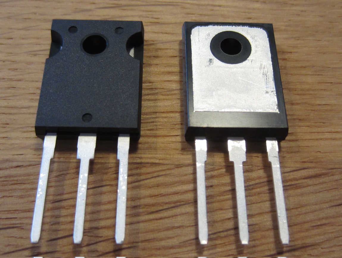
Zwei Leistungshalbleiter im TO-220 Gehäuse
IGBT_Pollin_130906_2010.jpg
in „Halbleiter, echt oder gefälscht“ · Analoge Elektronik und Schaltungstechnik · · Fotos

-
PDF
pollin_D350712D.pdf
150W POWER SUPPLY FOR TFTD ISPLAYS Release: 23.02.2004 1 1 Change history No. Change Date 01 First edition / Release Version 18.12.2003 02 Output power reduced 29.01.2004 03 Stand-By-Concept changed 23.02.2004 04 05 06 07 08 09 10 2 Introduction The 150W power supply for TFTs generates from the Line-Input-Voltage (200VAC-264VAC) different DC output-voltages which are used to drive a TFT up to 30” and the other electronics, incl speaker. The SMPS has an active-Power-Factor-Control (PFC). It has an integrated controller for overload-protection ad communication with external peripherals. The controller analyses
in „Conrac Power Supply 150W“ · Mikrocontroller und Digitale Elektronik ·
-
PDF
pollin_lcd_128_64.pdf
TG12864B-05 ■ Series ■ Electrical Characteristics Standard value Display Format 128 X 64 DOTS ITEM Symbol Condition UNIT Min. Typ. Max. Drive Method 1/64 Duty ; 1/9 Bias Supply Voltage For Logic V DD SS -- 4.5 5.0 5.5 V Supply Voltage For LCD VDDV 0 -- -- 9.0 -- V LCD Type STN/Transflective/positive Y/G Input High Voltage V -- 0.7V -- V V IH DD DD LED Backlight Yellow Input Low Voltage V IL -- 0 -- 0.3VDD V Supply Current for Logic DD -- -- 6.0 -- mA Viewing direction 6:00 Supply Current for LCD EE -- -- 4.5 -- mA Operating -20¥~70¥ With B/L(Yellow-Green) ILED VLED=5.0V -- 330 660 mA Temperature
in „Problem mit Displaydatenblatt“ · Mikrocontroller und Digitale Elektronik ·
-
Datei
RFM12_Pollin_TX.c
Software_SCK); aCmd<<=1; } SPI_PORT |= (1<<Software_SEL); return(temp); } void RF12TX_INIT(void) //Pollin Beipackzettel { RF12_WRT_CMD(0x80D7);//EL,EF,12.0pF RF12_WRT_CMD(0x8239);//!er,!ebb,ET,ES,EX,!eb,!ew,DC RF12_WRT_CMD(0xA640);//A140=430.8MHz RF12_WRT_CMD(0x94A0);//VDI,FAST,134kHz,0dBm,-103dBm RF12
in „RFM12 Empfang (nicht schon wieder.)“ · Mikrocontroller und Digitale Elektronik ·
-
Datei
RMF12_Pollin_RX.c
#include <avr/io.h> #define SPI_PORT PORTB #define SPI_DDR DDRB #define SPI_PIN PINB #define Software_MISO PB3 #define Software_MOSI PB2 #define Software_SCK PB1 #define Software_SEL PB4 #define nIRQ_PORT PORTD #define RF12_nIRQ PD2 void Software_SPI_Init(void) { SPI_DDR = (1<<Software_MOSI)|(1<<Software_SCK)|(1<<Software_SEL); //MOSI, SCK und SS müssen Ausgang sein SPI_PORT|= (1<<Software_SEL)|(1<<Software_MOSI); } unsigned int RF12_WRT_CMD(unsigned int aCmd) { unsigned char i; unsigned int temp = 0; SPI_PORT &=~(1<<Software_SCK); SPI_PORT &=~(1<<Software_SEL); for(i=0;i<16;i++) { if(aCmd&0x8000) { SPI_PORT
in „RFM12 Empfang (nicht schon wieder.)“ · Mikrocontroller und Digitale Elektronik ·
-
Datei
pollin-pnx8950_combined.diff
save memory */ -#define CFG_PROMPT "SilverBox # " /* Monitor Command Prompt */ +#define CFG_PROMPT "Pollin PNX8950 # " /* Monitor Command Prompt */ #define CFG_CBSIZE 256 /* Console I/O Buffer Size */ #define CFG_PBSIZE (CFG_CBSIZE + sizeof(CFG_PROMPT) + 16) /* Print Buffer Size */ #define CFG_MAXARGS 16
in „Pollin - Receiver-Mainboard mit Twin DVB-[T,C] Tuner, NXP PNX8950EH“ · Mikrocontroller und Digitale Elektronik ·