and the bus must be held high by the pullup for the duration of the conversion (t CONV ) or data transfer (t WR = 10ms). No other activity can take place on the 1-Wire bus while the pullup is enabled. Also nach Command den Ausgang mit Totempole auf High (nicht einfach nur open collector sperren)
Transaction. The minimum for any international order is $100.00. Wire Transfers: A $30.00 wire transfer fee will be added to all orders. Der deutsche Online-Shop rechnet per Default mit US-Dollar. Just Honest. Homepage: Kleines Sortiment von Bauteilen günstiger Versand (ab 1,90 €) günstige ZIF-Sockel
Ohm erhältlich (€4,17) Versandkosten €10,12 Stand 28.11.2018, auch Kleinmengen an Hobbyisten TME (Transfer Multisort Elektronik). Homepage: breites Sortiment parametrische Suche Verkauf über die deutsche Tochter (19 % statt 21 % polnische Umsatzsteuer) Versandkosten (D): 8,21 € inkl. MWSt. (Stand: 13.08.2025
- und SPI-Protokoll-Dekoder. Vier oder zwei Kanäle mit bis zu 24 MHz Abtastrate. USB-High-Speed-Transfer zur kontinuierlichen Datenspeicherung. Aufzeichnung über Tage hinweg (nur durch Festplatte begrenzt). Preis 99,- Euro incl. MwSt. Eine Übersicht über verschiedene Selbstbauprojekte: Logic_Analyzer
erst ab High-Speed (480 MBit/sec). Die 64 Byte beziehen sich aber auf den Inhalt eines Pakets ("Transfer"). Pro Frame können mehere Pakete ("Transfers") übertragen werden. Bei 64 Byte Nutzdaten pro Paket sind das maximal 13 Pakete pro Frame, d.h. 832 Byte. Und damit liegt die maximale Nutzdatenrate
, habe ich noch nie durch das Ding bekommen. Noch nicht einmal > ansatzweise. Setzt "bulk" transfer voraus. Früher(tm) gab es USB-IDE-Adapter, die nur Fullspeed konnten (weil es damals Highspeed noch gar nicht gab), mit denen lag' man bei eben jenen 800 kByte/sec. Einer der wenigen USB-SCSI-Adapter
Pixelarchitektur namens ST DeepNIR, die für Infrarotbildgebung optimiert ist. Mit 35 % höherer Modulation Transfer Function-(MTF)-Schärfe und nahezu 60 % höherer Quanteneffizienz als die vorherige Generation ist der VD56GA derzeit der einzige Sensor seiner Klasse, der dieses Niveau an kombinierter optischer Auflösung
Anlaufstrom 100 mAh Hüstel... wohl eher 100mA. Optokoppler haben als einen Kennwert "Current Transfer Ratio", einen maximalen Collectorstrom und einen maximalen Eingangsstrom für die Sendediode.
> Optokoppler haben als einen Kennwert "Current Transfer Ratio", einen maximalen > Collectorstrom und einen maximalen Eingangsstrom für die Sendediode. Ausserdem haben sie noch eine sehr begrenzte Lebensdauer wenn man nicht deutlich von den Maximalwerten
guaranteed by the digital control electrotechnology together with superior-quality sensor and heat-transfer technology. High-speId measured-value acquisition provides for maximum temperature precision and optimum dynamic temperature performance in load situations. E All soldering irons (except for microtools
etwas Störabstand zu haben. Leider hält sich Philips/NXP ziemlich bedeckt, was die "Typical Transfer Characteristics" angeht. Aber im Datenblatt zum 74HCU04 findet man sie. Ob die Eingänge des PCF8574 ein-, zwei- oder dreifach gebuffert sind, darüber schweigt sich Philips auch aus. Aber typisch wären
°C, unless otherwise noted.) A MAX9_1/MAX972/MAX9_4 RESPONSE TIME vs. RESPONSE TIME FOR VARIOUS TRANSFER FUNCTION LOAD CAPACITANCE INPUT OVERDRIVES (V OHL ) 5.0 1 18 1 1 +5V T V- = 0V T T 4.5 10kΩ 1 1 5 1 100kΩ - 16 4 4 4.0 V 0 9 9 ) 9 ) M ) A ( 4 A ( 10µF s 14 M T 10mV M E 3.5 ( VOHL O 3 A E 12 V 100mV
high sensed on the auxiliary winding during the level protection features makes it suitable for transfer of transformer energy to the secondary. offline small power converter applications. Fig.º illustrates the CV sampling signal timing System Start-Up Operation waveform in JW1501A/B. As shown in Fig.º
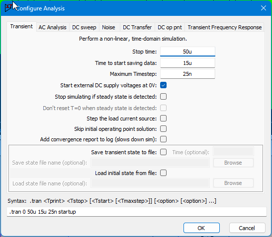
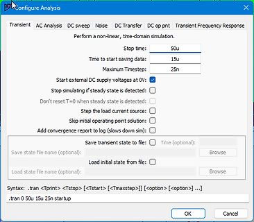
Configure Analysis
Transient AC Analysis DC sweep Noise DC Transfer DC op pnt Transient Frequency Response
Perform a non-linear, time-domain simulation.
Stop time: 50u
Time to start saving data: 15u
Maximum Timestep: 25n
Start external DC supply voltages at 0V
Stop
USB_CNTR = 1; // disable reset and int CMD.Configuration = 0; // nothing before CONFIGURED CMD.TransferLen = 0; // nothing to transfer CMD.PacketLen = 0; // nothing to transfer CMD.TransferPtr = 0; USB_CNTR = 0; // all int off suspended = false; configurationSet = false; transmitting = false; receiving
USB: USB2.0/USB1.1-compatible full-speed USB, 6 bidirectional endpoints, supporting four endpoint transfer types (control, interrupt, bulk, and isochronous); each endpoint has a 64-byte buffer. ✓ I2S: audio bus. ✓ MDU32: hardware 32-bit multiply/divide unit (including 32-bit / 32-bit division and 32-bit
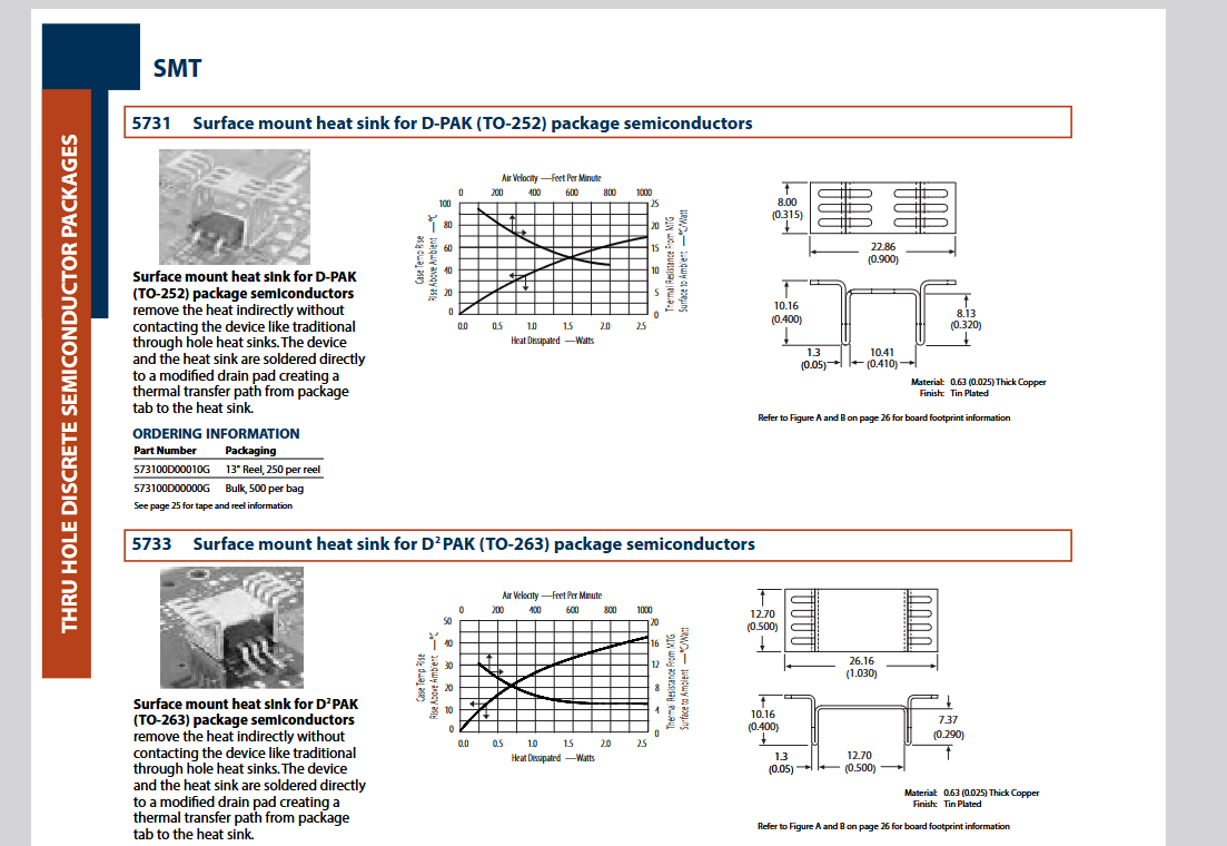
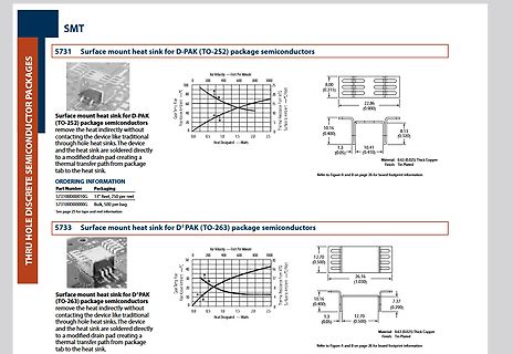
hole heat sinks. The heat sink are soldered directly to a modified drain pad creating a thermal transfer path from package tab to the heat sink.
ORDERING INFORMATION
Part Number
5731010G 13" Reel, 250 per reel
5731000G Bulk, 50 per bag
5733 Surface mount heat sink for D2 PAK (TO-263) package semiconductors
USB_CNTR = 1; // disable reset and int CMD.Configuration = 0; // nothing before CONFIGURED CMD.TransferLen = 0; // nothing to transfer CMD.PacketLen = 0; // nothing to transfer CMD.TransferPtr = 0; USB_CNTR = 0; // all int off suspended = false; configurationSet = false; transmitting = false; receiving
// disable reset and int CMD.Configuration = 0; // nothing before CONFIGURED CMD.TransferLen = 0; // nothing to transfer CMD.PacketLen = 0; // nothing to transfer CMD.TransferPtr = 0; USB_CNTR = 0; // all int off suspended = false; configurationSet
Vielleicht so: [c]CMD.TransferPtr = Buf; DescriptorBlockwiseIn(); CMD.TransferPtr = NULL;[/c]
D0 Screen Peeking (E0H) 1 1 1 0 0 0 0 0 This single byte command is used to ↓ STA0=1 & STA1=1? transfer 1 byte of displayed data to the D1 (Addrs Data) data stack and may be read by the MPU ↓ STA0=1 & STA1=1? using a Data Read command (section ↓ Y 8.7). This command is useful to read the D2 (Addrs Data
T6963C ● Screen Peek Code Hex. Function Operand 11100000 E0H Screen Peek ― This command is used to transfer 1 byte of displayed data to the data stack; this byte can then be read from the MPU by data access. The logical combination of text and graphic display data on the LCD screen can be read by this command
; // Transfers value from shadow timer registers to actual timer registers XMC_CCU4_EnableShadowTransfer(CCU43, XMC_CCU4_SHADOW_TRANSFER_SLICE_3 | XMC_CCU4_SHADOW_TRANSFER_PRESCALER_SLICE_3); // Bind period match event to an NVIC node CCU43_1_IRQn XMC_CCU4_SLICE_SetInterruptNode(CCU43_CC43, XMC_CCU4_
; // Transfers value from shadow timer registers to actual timer registers XMC_CCU4_EnableShadowTransfer(CCU43, XMC_CCU4_SHADOW_TRANSFER_SLICE_3 | XMC_CCU4_SHADOW_TRANSFER_PRESCALER_SLICE_3); // Bind period match event to an NVIC node CCU43_1_IRQn XMC_CCU4_SLICE_SetInterruptNode(CCU43_CC43, XMC_CCU4_
Nashorn". Die KI ist das Nashorn. Mehr will ich nicht spoilern denn das bisschen an restlichen Transfer wirst du schon noch hinbekommen. Ich hoffe es zumindest. Fühle ich mich jetzt besser: Selbstverständlich. Ich spreche das aus, was längst hätte ausgesprochen werden sollen. Ich bin ehrlich. Und
Transfers value from shadow timer registers to actual timer registers */ XMC_CCU4_EnableShadowTransfer(CCU43, XMC_CCU4_SHADOW_TRANSFER_SLICE_3 | XMC_CCU4_SHADOW_TRANSFER_PRESCALER_SLICE_3); /* Bind period match event to an NVIC node CCU43_1_IRQn */ XMC_CCU4_SLICE_SetInterruptNode(CCU43_CC43,
auf EEPROM-Werte verbessert. STM32 Version 2.6.5. Optimierung: Double-Buffering für SK6812-DMA-Transfer - analog zu WS2812 in Version 2.6.4. Bugfix: Update von undefinierten EEPROM-Inhalten, welche in 2.6.x zu Hangups führen konnten. Bugfix: Nach Spielen von Tetris wurde nicht immer die aktuelle Uhrzeit
40 Troubleshooting Guide 1–41 0–0 Page Page Utilities for Printouts Specifications 5– 1 or Data Transfer Accessories (Options) 5– 9 Data Output Parameter 2– 9 Index 6– 1 Auto Print 2– 9 Data Output at Supplement: Defined Intervals 2–10 Data ID Codes 2–11 Brief Instructions Automatic Output of the Card
reversed until the flux furtherdecays,finally permitting available spring “return”forces to cause transfer to continue. It is equally important to realize that when the contacts of a typical power 10V/Div. Ref. relay make, connecting very fast rising (e.g., resistive) medium or high current loads to the
method. Once the BIU has been granted bus mastership, it will perform a series of consecutive data transfer cycles be Reinitialization fore relinquishing the bus. Each data transfer will be The transmitter and receiver section of the PCnetISA + performed sequentially, with the issue of the address, controller
不可出现太少或高低不平等现象。 In order to reduce the contact thermal resistance during assembly, please note that the heat transfer paste of good quality is applied evenly and the distribution area is reasonable during the assembly process, and there is no too little or unequal height. ● 散热介质需保证电介质耐压测试至少通过 500V。 The heat dissipation
Executetheabstractcommandandthenexecute 0 the command in progbuf 0: Do not execute the operation specified by write 17 transfer WO 0 1: Execute the manipulation specified by write 0: Copy data from the specified register to data0 16 write WO 1: Copy data from data0 register to the specified 0 register Specify access registers
configured by the software setting. There are two mode commands to con-figure the ET6622 resource and to transfer the LCD display data. Operation Mode ID READ Data 1 1 0 WRITE Data 1 0 1 READ-MODIFY-WRITE Data 1 0 1 COMMAND Command 1 0 0 If successive commands have been issued, the command mode ID can be omitted
Characteristics Input Capacitance Ciss 2028 Output Capacitance Coss V DS0V,V =GS,f=1MHz 756 pF Reverse Transfer Capacitance C 41 rss Total Gate Charge Q g 34 Gate-Source Charge Qgs V DS0V,V =GSV,I =2DA 11 nC Gate-Drain Charge Qgd 8 t Turn-On Delay Time d(on) 12 V =30V, V =10V, Turn-On Rise Time r DS GS 32 R
writing are authorized to perform service and repairs covered by an Alesis warranty (if any), and transfer of the Manual to you does not authorize you to be an authorized Service Center. Therefore, if you perform, or if the Manual is used to perform, any service or repairs on any Alesis product or part
Ansitzstange. Auch Reineke Fuchs könnt sich gern mal ne Portion: https://image.jimcdn.com/app/cms/image/transf/none/path/sdf6d4a6f2852982c/image/i44ef4c72ff840424/version/1699527212/image.png
übertragen, verfügt das Gerät über eine eingebaute IR‐ Schnittstelle. IET bietet ein optionales Data Transfer Kit (DE‐5000‐DTK). Dieses Kit enthält: IR‐USB‐Schnittstellenadapter, ein USB‐Kabel und eine CD mit Software für den PC. 1.2. Einführung in die Messprinzipien 1.2.1. Was ist Impedanz Impedanz (Z) besteht

 Bild
Bild
 Bild
Bild
 Bild
Bild
 Bild
Bild
 Bild
Bild