Hey Leute. Habe einen LED Cube gebaut. 4x4x4. 16 Ausgänge für die 16
Reihen. Hatte schon einen µC verfused. Wobei dort aber alle 16 Reihen
funktioniert hatten. Mit dem neuen Funktionieren auf einmal 4 Reichen
nicht mehr. Woran kann das liegen. 3 der 4 Reihen Leuchten ganz schwach,
und die ganze zeit. Die andere gar nicht. Hatte nichts geändert außer
den µC gerauscht.

Hoffe heute ist noch jemand da. Sollte nämlich ein Weihnachtsgeschenk
werden.

Danke Leute. Und frohe Weihnachten.
Auch wenn heute Weihnachten ist, scheinen es manche einfach nicht zu
kappieren:

Poste deine Schaltung, deinen Code und was sonst noch so dazu gehört.
Woher sollen  wir denn wissen, was du gedreht hast!!
kopfschüttel
Hab das Programm nicht selbst geschrieben. Sondern eine Fertige tmp
Datei raufgespielt. Und es ging ja bei dem anderen µC auch. Aber kann ja
mal trotzdem den Code posten:

In meinem fall sind es die Ausgänge C2-5 die nicht funktionieren.


// ############################################
//
// 4x4x4 LED Cube project
// By Christian Moen 2008
// chr@syntaks.org
// Lisence: GPL
//
// ############################################

#include <avr/io.h>
#include <avr/interrupt.h>
#include <avr/pgmspace.h>

// Define USART stuff
// CPU speed and baud rate:
#define FOSC 14745600
#define BAUD 9600
// Are used to calculate the correct USART timings
#define MYUBRR (((((FOSC * 10) / (16L * BAUD)) + 5) / 10) - 1)


// Define masks used for status LEDs and input buttons.
#define LED_GREEN 0x01
#define LED_RED 0x02
#define BUTTON 0x08
// Define port used for status and input.
#define LED_PORT PORTB
#define BUTTON_PORT PORTB


// Define masks for the layer select.
#define LAYER1 0x80
#define LAYER2 0x40
#define LAYER3 0x20
#define LAYER4 0x10
#define LAYERS 0xf0 // All layers
#define LAYERS_R 0x0f // The inverse of the above.
#define LAYER_PORT PORTD

// Define LED grid ports
// Each of the grid ports are connected to two rows of leds.
// The upper 4 bits is one row, the lower 4 bits are one row.
#define GRID1 PORTC
#define GRID2 PORTA


void ioinit (void); // initiate IO on the AVR
void bootmsg (void); // blink some leds to indicate boot or reboot
void delay_ms (uint16_t x); // delay function used throughout the
program
void led_red(unsigned char state); // led on or off
void led_green(unsigned char state);
void launch_effect (int effect); // effect program launcher

// *** Cube buffer ***
// The 3D image displayed on the cube is buffered in a 2d array 'cube'.
// The 1st dimension in this array is the Z axis of the cube.
// The 2nd dimension of the array is the Y axis.
// Each byte is a stripe of leds running along the X axis at the given
// Z and Y coordinates.
// Only the 4 lower bits are used, since the cube is only 4x4x4.
// This buffer design was chosen to have code compatability with a 8x8x8
cube.
// "volatile" makes the variables reachable from within the interrupt
functions
volatile unsigned char cube[4][4];

// We sometimes want to draw into a temporary buffer so we can modify it
// before writing it to the cube buffer.
// e.g. invert, flip, reverse the cube..
volatile unsigned char tmpcube[4][4];

// What layer the interrupt routine is currently showing.
volatile unsigned char current_layer;

// Low level geometric functions
#include "draw.c"

// Static animation data
#include "frames.c"

// Fancy animations to run on the cube
#include "effect.c"


int main (void)
{
  // Initiate IO ports and peripheral devices.
  ioinit();

  // Indicate that the device has just booted.
  bootmsg();

  int x;
  int i;
  int z;

  // Set the layer to start drawing at
  current_layer = 0x00;

  // Enable interrupts to start drawing the cube buffer.
  // When interrupts are enabled, ISR(TIMER2_COMP_vect)
  // will run on timed intervalls.
  sei();

  // Main program loop.
  while (1)
  {
    for (i=0;i<13;i++)
    {
      launch_effect(i);
    }
    // Comment the loop above and uncomment the line below
    // if you want the effects in random order (produced some bugs.. )
    //launch_effect(rand()%13);
  }

}

// Launches one of those fancy effects.
void launch_effect (int effect)
{
  switch (effect)
  {
    // Lights all the layers one by one
    case 0:
      loadbar(1000);
      break;

    // A pixel bouncing randomly around
    case 1:
      // blink
      boingboing(150,500,0x03,0x01);
      break;

    // Randomly fill the cube
    // Randomly empty the cube
    case 2:
      fill(0x00);
      random_filler(100,1,500,1);
      random_filler(100,1,500,0);
      break;

    // Send voxels randomly back and forth the Z axis
    case 3:
      sendvoxels_rand_z(150,500,2000);
      break;

    // Spinning spiral
    case 4:
      effect_spiral(1,75,1000);
      break;

    // A coordinate bounces randomly around the cube
    // For every position the status of that voxel is toggled.
    case 5:
      // toggle
      boingboing(150,500,0x03,0x02);
      break;

    // Random raindrops
    case 6:
      effect_rain(20,5000,3000,500);
      break;

    // A snake randomly bounce around the cube.
    case 7:
      // snake
      boingboing(150,500,0x03,0x03);
      break;

    // Spinning plane
    case 8:
      effect_spinning_plane(1,50,1000);
      break;

    // set x number of random voxels, delay, unset them.
    // x increases from 1 to 20 and back to 1.
    case 9:
      random_2();
      break;

    // Set all 64 voxels in a random order.
    // Unset all 64 voxels in a random order.
    case 10:
      random_filler2(200,1);
      delay_ms(2000);
      random_filler2(200,0);
      delay_ms(1000);
      break;

    // bounce a plane up and down all the directions.
    case 11:
      flyplane("z",1,1000);
      delay_ms(2000);
      flyplane("y",1,1000);
      delay_ms(2000);
      flyplane("x",1,1000);
      delay_ms(2000);
      flyplane("z",0,1000);
      delay_ms(2000);
      flyplane("y",0,1000);
      delay_ms(2000);
      flyplane("x",0,1000);
      delay_ms(2000);
      break;

    // Fade in and out at low framerate
    case 12:
      blinky2();
      break;
  }
}

// ** Diagnostic led functions **

// Set or unset the red LED
void led_red(unsigned char state)
{
  if (state == 0x00)
  {
    LED_PORT &= ~LED_RED;
  } else
  {
    LED_PORT |= LED_RED;
  }
}

// Set or unset the green LED
void led_green(unsigned char state)
{
  if (state == 0x00)
  {
    LED_PORT &= ~LED_GREEN;
  } else
  {
    LED_PORT |= LED_GREEN;
  }
}


// Cube buffer draw interrupt routine
ISR(TIMER2_COMP_vect)
{

  // AND the reverse bitmask onto the layer port.
  // This disables all the layers. rendering all the leds off.
  // We don't want to see the cube updating.
  LAYER_PORT &= LAYERS_R;

  // Take the current 2D image at the current layer along the Z axis
  // and place it on the LED grid.
  GRID1 = (0x0f & cube[current_layer][0]) | (0xf0 &
(cube[current_layer][1] << 4));
  GRID2 = (0x0f & cube[current_layer][2]) | (0xf0 &
(cube[current_layer][3] << 4));

  // Enable the apropriate layer
  LAYER_PORT |= (0x01 << (7 - current_layer));

  // The cube only has 4 layers (0,1,2,3)
  // If we are at layer 3 now, we want to go back to layer 0.
  if (current_layer++ == 3)
    current_layer = 0;
}

void ioinit (void)
{
  // ### Initiate I/O

  // Data Direction Registers
  // Bit set to 1 means it works as an output
  // Bit set to 1 means it is an input
  DDRA = 0xff;  // Inner cube byte
  DDRB = 0xf7;  // ISP and 0-1: led. 3: button
  DDRC = 0xff;  // Outer cube byte
  DDRD = 0xff;  // Layer select

  // Set all ports OFF, and enable pull up resistors where needed.
  PORTA = 0x00;
  PORTC = 0x00;
  PORTB = 0x08; // Enable pull up button.
  PORTD = 0x00;

  // ### Initiate timers and USART

  // Frame buffer interrupt
  TCNT2 = 0x00;  // initial counter value = 0;
  TIMSK |= (1 << OCIE2); // Enable CTC interrupt

  // Every 1024th cpu cycle, a counter is incremented.
  // Every time that counter reaches 15, it is reset to 0,
  // and the interrupt routine is executed.
  // 14745600/1024/15 = 960 times per second
  // There are 4 layers to update..
  // 14745600/1024/15/4 = 240 FPS
  // == flicker free :)
  OCR2 = 15;       // interrupt at counter = 15
  TCCR2 = 0x05;     // prescaler = 1024
  TCCR2 |= (1 << WGM01);  // Clear Timer on Compare Match (CTC) mode


  // Initiate RS232
  // USART Baud rate: 9600
  UBRRH = MYUBRR >> 8;
  UBRRL = MYUBRR;
  // UCSR0C - USART control register
  // bit 7-6      sync/ascyn 00 = async,  01 = sync
  // bit 5-4      parity 00 = disabled
  // bit 3        stop bits 0 = 1 bit  1 = 2 bits
  // bit 2-1      frame length 11 = 8
  // bit 0        clock polarity = 0
  UCSRC  = 0b10000110;
  // Enable RS232, tx and rx
  UCSRB = (1<<RXEN)|(1<<TXEN);
  UDR = 0x00; // send an empty byte to indicate powerup.

}


// Blink the status LEDs a little to indicate that the device has just
booted.
// This is usefull to see if an error is making the device reboot when
not supposed to.
// And it looks cool.
void bootmsg (void)
{
  int i;
  LED_PORT |= LED_GREEN;
  for (i = 0; i < 2; i++)
  {
    // Blinky
    delay_ms(1000);
    LED_PORT &= ~LED_GREEN;
    LED_PORT |= LED_RED;
    // Blink
    delay_ms(1000);
    LED_PORT &= ~LED_RED;
    LED_PORT |= LED_GREEN;
  }
  delay_ms(1000);
  LED_PORT &= ~LED_GREEN;
}


// Delay function used in graphical effects.
void delay_ms(uint16_t x)
{
  uint8_t y, z;
  for ( ; x > 0 ; x--){
    for ( y = 0 ; y < 90 ; y++){
      for ( z = 0 ; z < 6 ; z++){
        asm volatile ("nop");
      }
    }
  }
}

Wäre schon super wenn mir jemand ein kleines Grundgerüst schicken könnte
was ich alles initialisieren muss und so um dann einfach nur die
Ausgänge zu setzen. Hab leider wirklich noch nicht so viel Ahnung davon.
Jetzt formatieren wir das ganze noch leserlich und hängen noch den
Schaltplan dazu, dann gibts vielleicht heute noch n paar Geschenke vom
Weihnachtsmann...
Angehängte Dateien:
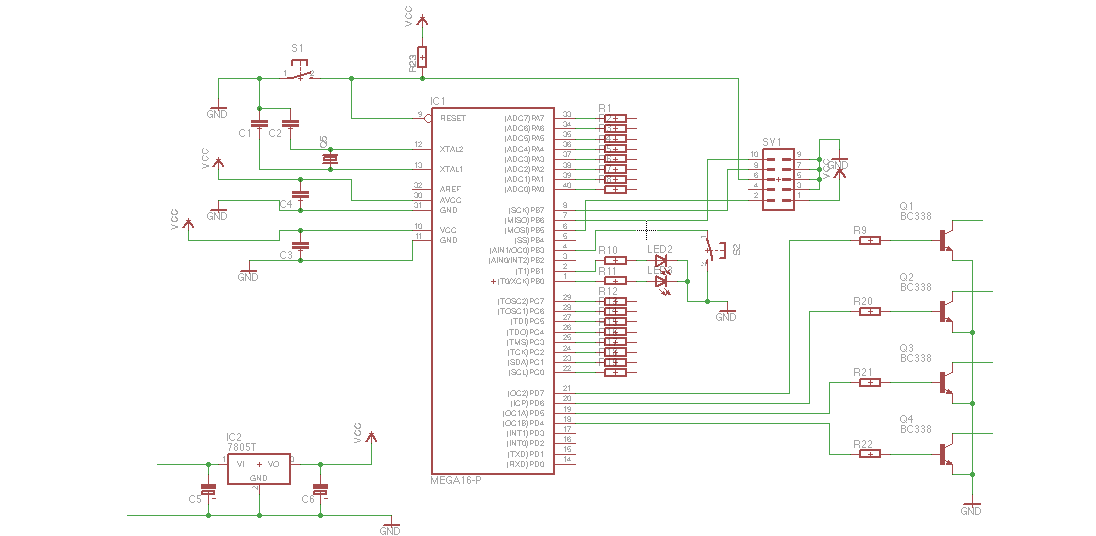
So. Schaltplan.

Und hier formatiert :-). Sorry, hatte nicht gesehen dass das geht.
1 | // ############################################
|
2 | //
|
3 | // 4x4x4 LED Cube project
|
4 | // By Christian Moen 2008
|
5 | // chr@syntaks.org
|
6 | // Lisence: GPL
|
7 | //
|
8 | // ############################################
|
9 | |
10 | #include <avr/io.h> |
11 | #include <avr/interrupt.h> |
12 | #include <avr/pgmspace.h> |
13 | |
14 | // Define USART stuff
|
15 | // CPU speed and baud rate:
|
16 | #define FOSC 14745600
|
17 | #define BAUD 9600
|
18 | // Are used to calculate the correct USART timings
|
19 | #define MYUBRR (((((FOSC * 10) / (16L * BAUD)) + 5) / 10) - 1)
|
20 | |
21 | |
22 | // Define masks used for status LEDs and input buttons.
|
23 | #define LED_GREEN 0x01
|
24 | #define LED_RED 0x02
|
25 | #define BUTTON 0x08
|
26 | // Define port used for status and input.
|
27 | #define LED_PORT PORTB
|
28 | #define BUTTON_PORT PORTB
|
29 | |
30 | |
31 | // Define masks for the layer select.
|
32 | #define LAYER1 0x80
|
33 | #define LAYER2 0x40
|
34 | #define LAYER3 0x20
|
35 | #define LAYER4 0x10
|
36 | #define LAYERS 0xf0 // All layers
|
37 | #define LAYERS_R 0x0f // The inverse of the above.
|
38 | #define LAYER_PORT PORTD
|
39 | |
40 | // Define LED grid ports
|
41 | // Each of the grid ports are connected to two rows of leds.
|
42 | // The upper 4 bits is one row, the lower 4 bits are one row.
|
43 | #define GRID1 PORTC
|
44 | #define GRID2 PORTA
|
45 | |
46 | |
47 | void ioinit (void); // initiate IO on the AVR |
48 | void bootmsg (void); // blink some leds to indicate boot or reboot |
49 | void delay_ms (uint16_t x); // delay function used throughout the program |
50 | void led_red(unsigned char state); // led on or off |
51 | void led_green(unsigned char state); |
52 | void launch_effect (int effect); // effect program launcher |
53 | |
54 | // *** Cube buffer ***
|
55 | // The 3D image displayed on the cube is buffered in a 2d array 'cube'.
|
56 | // The 1st dimension in this array is the Z axis of the cube.
|
57 | // The 2nd dimension of the array is the Y axis.
|
58 | // Each byte is a stripe of leds running along the X axis at the given
|
59 | // Z and Y coordinates.
|
60 | // Only the 4 lower bits are used, since the cube is only 4x4x4.
|
61 | // This buffer design was chosen to have code compatability with a 8x8x8 cube.
|
62 | // "volatile" makes the variables reachable from within the interrupt functions
|
63 | volatile unsigned char cube[4][4]; |
64 | |
65 | // We sometimes want to draw into a temporary buffer so we can modify it
|
66 | // before writing it to the cube buffer.
|
67 | // e.g. invert, flip, reverse the cube..
|
68 | volatile unsigned char tmpcube[4][4]; |
69 | |
70 | // What layer the interrupt routine is currently showing.
|
71 | volatile unsigned char current_layer; |
72 | |
73 | // Low level geometric functions
|
74 | #include "draw.c" |
75 | |
76 | // Static animation data
|
77 | #include "frames.c" |
78 | |
79 | // Fancy animations to run on the cube
|
80 | #include "effect.c" |
81 | |
82 | |
83 | int main (void) |
84 | {
|
85 | // Initiate IO ports and peripheral devices.
|
86 | ioinit(); |
87 | |
88 | // Indicate that the device has just booted.
|
89 | bootmsg(); |
90 | |
91 | int x; |
92 | int i; |
93 | int z; |
94 | |
95 | // Set the layer to start drawing at
|
96 | current_layer = 0x00; |
97 | |
98 | // Enable interrupts to start drawing the cube buffer.
|
99 | // When interrupts are enabled, ISR(TIMER2_COMP_vect)
|
100 | // will run on timed intervalls.
|
101 | sei(); |
102 | |
103 | // Main program loop.
|
104 | while (1) |
105 | {
|
106 | for (i=0;i<13;i++) |
107 | {
|
108 | launch_effect(i); |
109 | }
|
110 | // Comment the loop above and uncomment the line below
|
111 | // if you want the effects in random order (produced some bugs.. )
|
112 | //launch_effect(rand()%13);
|
113 | }
|
114 | |
115 | }
|
116 | |
117 | // Launches one of those fancy effects.
|
118 | void launch_effect (int effect) |
119 | {
|
120 | switch (effect) |
121 | {
|
122 | // Lights all the layers one by one
|
123 | case 0: |
124 | loadbar(1000); |
125 | break; |
126 | |
127 | // A pixel bouncing randomly around
|
128 | case 1: |
129 | // blink
|
130 | boingboing(150,500,0x03,0x01); |
131 | break; |
132 | |
133 | // Randomly fill the cube
|
134 | // Randomly empty the cube
|
135 | case 2: |
136 | fill(0x00); |
137 | random_filler(100,1,500,1); |
138 | random_filler(100,1,500,0); |
139 | break; |
140 | |
141 | // Send voxels randomly back and forth the Z axis
|
142 | case 3: |
143 | sendvoxels_rand_z(150,500,2000); |
144 | break; |
145 | |
146 | // Spinning spiral
|
147 | case 4: |
148 | effect_spiral(1,75,1000); |
149 | break; |
150 | |
151 | // A coordinate bounces randomly around the cube
|
152 | // For every position the status of that voxel is toggled.
|
153 | case 5: |
154 | // toggle
|
155 | boingboing(150,500,0x03,0x02); |
156 | break; |
157 | |
158 | // Random raindrops
|
159 | case 6: |
160 | effect_rain(20,5000,3000,500); |
161 | break; |
162 | |
163 | // A snake randomly bounce around the cube.
|
164 | case 7: |
165 | // snake
|
166 | boingboing(150,500,0x03,0x03); |
167 | break; |
168 | |
169 | // Spinning plane
|
170 | case 8: |
171 | effect_spinning_plane(1,50,1000); |
172 | break; |
173 | |
174 | // set x number of random voxels, delay, unset them.
|
175 | // x increases from 1 to 20 and back to 1.
|
176 | case 9: |
177 | random_2(); |
178 | break; |
179 | |
180 | // Set all 64 voxels in a random order.
|
181 | // Unset all 64 voxels in a random order.
|
182 | case 10: |
183 | random_filler2(200,1); |
184 | delay_ms(2000); |
185 | random_filler2(200,0); |
186 | delay_ms(1000); |
187 | break; |
188 | |
189 | // bounce a plane up and down all the directions.
|
190 | case 11: |
191 | flyplane("z",1,1000); |
192 | delay_ms(2000); |
193 | flyplane("y",1,1000); |
194 | delay_ms(2000); |
195 | flyplane("x",1,1000); |
196 | delay_ms(2000); |
197 | flyplane("z",0,1000); |
198 | delay_ms(2000); |
199 | flyplane("y",0,1000); |
200 | delay_ms(2000); |
201 | flyplane("x",0,1000); |
202 | delay_ms(2000); |
203 | break; |
204 | |
205 | // Fade in and out at low framerate
|
206 | case 12: |
207 | blinky2(); |
208 | break; |
209 | }
|
210 | }
|
211 | |
212 | // ** Diagnostic led functions **
|
213 | |
214 | // Set or unset the red LED
|
215 | void led_red(unsigned char state) |
216 | {
|
217 | if (state == 0x00) |
218 | {
|
219 | LED_PORT &= ~LED_RED; |
220 | } else |
221 | {
|
222 | LED_PORT |= LED_RED; |
223 | }
|
224 | }
|
225 | |
226 | // Set or unset the green LED
|
227 | void led_green(unsigned char state) |
228 | {
|
229 | if (state == 0x00) |
230 | {
|
231 | LED_PORT &= ~LED_GREEN; |
232 | } else |
233 | {
|
234 | LED_PORT |= LED_GREEN; |
235 | }
|
236 | }
|
237 | |
238 | |
239 | // Cube buffer draw interrupt routine
|
240 | ISR(TIMER2_COMP_vect) |
241 | {
|
242 | |
243 | // AND the reverse bitmask onto the layer port.
|
244 | // This disables all the layers. rendering all the leds off.
|
245 | // We don't want to see the cube updating.
|
246 | LAYER_PORT &= LAYERS_R; |
247 | |
248 | // Take the current 2D image at the current layer along the Z axis
|
249 | // and place it on the LED grid.
|
250 | GRID1 = (0x0f & cube[current_layer][0]) | (0xf0 & (cube[current_layer][1] << 4)); |
251 | GRID2 = (0x0f & cube[current_layer][2]) | (0xf0 & (cube[current_layer][3] << 4)); |
252 | |
253 | // Enable the apropriate layer
|
254 | LAYER_PORT |= (0x01 << (7 - current_layer)); |
255 | |
256 | // The cube only has 4 layers (0,1,2,3)
|
257 | // If we are at layer 3 now, we want to go back to layer 0.
|
258 | if (current_layer++ == 3) |
259 | current_layer = 0; |
260 | }
|
261 | |
262 | void ioinit (void) |
263 | {
|
264 | // ### Initiate I/O
|
265 | |
266 | // Data Direction Registers
|
267 | // Bit set to 1 means it works as an output
|
268 | // Bit set to 1 means it is an input
|
269 | DDRA = 0xff; // Inner cube byte |
270 | DDRB = 0xf7; // ISP and 0-1: led. 3: button |
271 | DDRC = 0xff; // Outer cube byte |
272 | DDRD = 0xff; // Layer select |
273 | |
274 | // Set all ports OFF, and enable pull up resistors where needed.
|
275 | PORTA = 0x00; |
276 | PORTC = 0x00; |
277 | PORTB = 0x08; // Enable pull up button. |
278 | PORTD = 0x00; |
279 | |
280 | // ### Initiate timers and USART
|
281 | |
282 | // Frame buffer interrupt
|
283 | TCNT2 = 0x00; // initial counter value = 0; |
284 | TIMSK |= (1 << OCIE2); // Enable CTC interrupt |
285 | |
286 | // Every 1024th cpu cycle, a counter is incremented.
|
287 | // Every time that counter reaches 15, it is reset to 0,
|
288 | // and the interrupt routine is executed.
|
289 | // 14745600/1024/15 = 960 times per second
|
290 | // There are 4 layers to update..
|
291 | // 14745600/1024/15/4 = 240 FPS
|
292 | // == flicker free :)
|
293 | OCR2 = 15; // interrupt at counter = 15 |
294 | TCCR2 = 0x05; // prescaler = 1024 |
295 | TCCR2 |= (1 << WGM01); // Clear Timer on Compare Match (CTC) mode |
296 | |
297 | |
298 | // Initiate RS232
|
299 | // USART Baud rate: 9600
|
300 | UBRRH = MYUBRR >> 8; |
301 | UBRRL = MYUBRR; |
302 | // UCSR0C - USART control register
|
303 | // bit 7-6 sync/ascyn 00 = async, 01 = sync
|
304 | // bit 5-4 parity 00 = disabled
|
305 | // bit 3 stop bits 0 = 1 bit 1 = 2 bits
|
306 | // bit 2-1 frame length 11 = 8
|
307 | // bit 0 clock polarity = 0
|
308 | UCSRC = 0b10000110; |
309 | // Enable RS232, tx and rx
|
310 | UCSRB = (1<<RXEN)|(1<<TXEN); |
311 | UDR = 0x00; // send an empty byte to indicate powerup. |
312 | |
313 | }
|
314 | |
315 | |
316 | // Blink the status LEDs a little to indicate that the device has just booted.
|
317 | // This is usefull to see if an error is making the device reboot when not supposed to.
|
318 | // And it looks cool.
|
319 | void bootmsg (void) |
320 | {
|
321 | int i; |
322 | LED_PORT |= LED_GREEN; |
323 | for (i = 0; i < 2; i++) |
324 | {
|
325 | // Blinky
|
326 | delay_ms(1000); |
327 | LED_PORT &= ~LED_GREEN; |
328 | LED_PORT |= LED_RED; |
329 | // Blink
|
330 | delay_ms(1000); |
331 | LED_PORT &= ~LED_RED; |
332 | LED_PORT |= LED_GREEN; |
333 | }
|
334 | delay_ms(1000); |
335 | LED_PORT &= ~LED_GREEN; |
336 | }
|
337 | |
338 | |
339 | // Delay function used in graphical effects.
|
340 | void delay_ms(uint16_t x) |
341 | {
|
342 | uint8_t y, z; |
343 | for ( ; x > 0 ; x--){ |
344 | for ( y = 0 ; y < 90 ; y++){ |
345 | for ( z = 0 ; z < 6 ; z++){ |
346 | asm volatile ("nop"); |
347 | }
|
348 | }
|
349 | }
|
350 | }
|
Benjamin Kriebel schrieb:
> Und hier formatiert :-). Sorry, hatte nicht gesehen dass das geht.
Und das, was hier ein paar Zeilen weiter unten steht, auch nicht:
1 | Antwort schreiben |
2 | Wichtige Regeln - erst lesen, dann posten! |
3 | Längeren Sourcecode nicht im Text einfügen, sondern als Dateianhang |
> So. Schaltplan.
Da könne keine LDEs leuchten. Da sind gar keine drin...

> Mit dem neuen Funktionieren auf einmal 4 Reichen nicht mehr.
Die können sich das eben leisten... ;-)

Nachdem der Code nicht von dir ist, und der Schaltplan so einfach
aufgebaut ist, dass eigentlich keine Fehler möglich sind, kanns nur noch
am Aufbau liegen: Kurzschluss, Transistor verpolt, ...
Wo sind die Reihen? Und welche leuchten nicht wie gewünscht?
Welche der Reihen (vermutlich die Transistoren) leuchten nicht wie
gewünscht?

> Hatte nichts geändert außer den µC gerauscht.
Ein besoffener uC könnte das alles erklären...
Also bei JTAGEN ist ein haken.

Also an jedem Ausgang sind immer 4 LEDs in parallel geschaltet und die
Masse über die Transistoren. Also so das jeweils die reihen sich VCC
teilen und die ebenen die masse. Wie gesagt. Die nicht funktionierenden
reihen leuchten ganz schwach, die ganze zeit
Juhu. Vielen dank. daran lag. Ist mir aber ein Rätsel. Denn bei dem
ersten IC hatte ich da nichts rumgestellt. Und da ging es ja auch. Egal.
Vielen dank und freche Weihnachten an euch alle.
Bitte melde dich an um einen Beitrag zu schreiben. Anmeldung ist kostenlos und dauert nur eine Minute.
Bestehender Account
Schon ein Account bei Google/GoogleMail? Keine Anmeldung erforderlich!
Mit Google-Account einloggen
Mit Google-Account einloggen
Noch kein Account? Hier anmelden.