Hallo,

Kurze Frage: welche von der 3(4) ICs wäre die beste Lösung, um einen K
Typ Temperatursensor auszulesen (auszuwerten)?
K Typ Sensor:
http://www.banggood.com/-50650-K-Type-Thermocouple-Probe-Digital-Temperature-Sensor-p-997580.html

-ADS1018
-Max31855 (MAX6675(alt))
-AD8497

Anforderungen: +- 1-2°C(Genauigkeit), max. 500°C, sollte auch nicht zu
langsam sein, preislich unten 6-10€ pro Teil

Bei Analog Devices handelt es sich wahrscheinlich um den nackten
Konverter. d.h. theoretisch mehr Programmieraufwand. TI hat SPI
Interface, Maxim Integrated eine I2C.

PS: Für mich sieht TI auf den ersten Blick der Gewinner zu sein. Oder
irre ich mich und der hat irgendwelche gravierende Nachteile?
PS2: Kennt jemand noch die Bezeichnung von der Büchse des K Typ Sensors?
(d.h. für das Einbau in einem Gehäuse)
Macht es Sinn statt ADS1018 einen ADS1118 zu holen?
http://www.ti.com/product/ADS1118

Die Geschwindigkeit mit der sich der Wert verändert, wäre mir wichtiger
als so eine Abweichung von 1-2°C

http://www.ti.com/product/ADS1118
Angehängte Dateien:
-

LogicAnaOut.PNG
6,1 KB
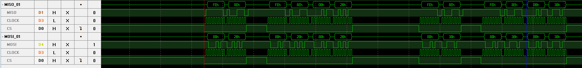
Thomas schrieb:
> Kann dir den ADS1118 empfehlen. Habe ich schon mehrfach verwendet ohne
> Probleme.

Hallo Thomas und alle anderen Wissenden ( ;) ),

Ich versuche seit einigen Stunden, den ADS1118 ans Laufen zu bekommen
und so richtig will es nicht.
Ich habe im Anhang ein Screenshot vom Logic Analyzer, der verrät, dass
der ADS den Befehl nicht zu akzeptieren scheint (bei der
32Bit-Übertragung werden am Ende nicht die gesendeten Config-Bytes
übertragen.
Bei Bedarf schick ich dir gern mehr als das minimale Anwendungsbeispiel
unten und wäre auch über deinen Code dankbar.
Der ADS soll ebenfalls mit einem Typ-K Sensor verwendet werden und der
ansteuernde µC ist ein ATMEGA8A, der mit nem Quarz auf 8MHz läuft.

Vielen Dank für die Hilfe,

Daniel


Anwendungsbeispiel:

aus main.c:
1 | //(...)
|
2 | void initialise(){ |
3 | spiInit(SPI_MODE_1, SPI_MSB, SPI_NO_INTERRUPT, |
4 | _delay_ms(500); |
5 | blinkLED(); |
6 | }
|
7 | //(...)
|
8 | int main(void) |
9 | {
|
10 | initialise(); |
11 | |
12 | |
13 | float temp1, temp2, temp3, temp4; |
14 | |
15 | |
16 | while (1) |
17 | {
|
18 | |
19 | // LED Status invertieren
|
20 | _delay_ms(500); |
21 | LEDPORT ^= (1<<LEDstatus); |
22 | |
23 | temp1 = perform16BitMeasurement(ADS_DEFAULT_CONFIG_LINKS); |
24 | _delay_us(100); |
25 | temp2 = perform16BitMeasurement(ADS_DEFAULT_CONFIG_LINKS_INT); |
26 | _delay_us(100); |
27 | temp3 = perform16BitMeasurement(ADS_DEFAULT_CONFIG_RECHTS); |
28 | _delay_us(100); |
29 | temp4 = perform16BitMeasurement(ADS_DEFAULT_CONFIG_RECHTS_INT); |
30 | _delay_ms(500); |
31 | }
|
32 | }
|
aus SPIinit.h
1 | #ifndef TRUE
|
2 | #define TRUE 1
|
3 | #endif
|
4 | |
5 | #ifndef FALSE
|
6 | #define FALSE 0
|
7 | #endif
|
8 | |
9 | |
10 | #include <avr/io.h> |
11 | #include <avr/interrupt.h> |
12 | #include <stdint.h> |
13 | #include <util/delay.h> |
14 | |
15 | #include <stdlib.h> |
16 | |
17 | |
18 | |
19 | |
20 | #ifndef SPIINIT_H_
|
21 | #define SPIINIT_H_
|
22 | |
23 | |
24 | //PinDef
|
25 | #define SPI_SS_STAT_REG PINB
|
26 | #define SPI_SS_PORT PORTB
|
27 | #define SPI_SS_PIN PORTB2
|
28 | #define SPI_SCK_PIN PORTB5
|
29 | #define SPI_MOSI_PIN PORTB3
|
30 | #define SPI_MISO_PIN PORTB4
|
31 | |
32 | //SPI clock modes
|
33 | #define SPI_MODE_0 0x00 /* Sample (Rising) Setup (Falling) CPOL=0, CPHA=0 */ |
34 | #define SPI_MODE_1 0x01 /* Setup (Rising) Sample (Falling) CPOL=0, CPHA=1 */ |
35 | #define SPI_MODE_2 0x02 /* Sample (Falling) Setup (Rising) CPOL=1, CPHA=0 */ |
36 | #define SPI_MODE_3 0x03 /* Setup (Falling) Sample (Rising) CPOL=1, CPHA=1 */ |
37 | |
38 | // data direction
|
39 | #define SPI_LSB 1 /* LSB first */ |
40 | #define SPI_MSB 0 /* MSB first */ |
41 | |
42 | // Interrupt when data received (SPIF bit received)
|
43 | #define SPI_NO_INTERRUPT 0
|
44 | #define SPI_INTERRUPT 1
|
45 | |
46 | // slave or master with clock div
|
47 | #define SPI_SLAVE 0xF0
|
48 | #define SPI_MSTR_CLK2 0x04 /* chip clock/2 */ |
49 | #define SPI_MSTR_CLK4 0x00 /* chip clock/4 */ |
50 | #define SPI_MSTR_CLK8 0x05 /* chip clock/8 */ |
51 | #define SPI_MSTR_CLK16 0x01 /* chip clock/16 */ |
52 | #define SPI_MSTR_CLK32 0x06 /* chip clock/32 */ |
53 | #define SPI_MSTR_CLK64 0x02 /* chip clock/64 */ |
54 | #define SPI_MSTR_CLK128 0x03 /* chip clock/128 */ |
55 | |
56 | |
57 | void spiInit( uint8_t mode, // timing mode SPI_MODE[0-4] |
58 | uint8_t dord, // data direction SPI_LSB|SPI_MSB |
59 | uint8_t interruptEnable, // whether to raise interrupt on recieve |
60 | uint8_t msClock); // clock diviser |
61 | |
62 | uint8_t spiTransceiveByte(uint8_t data, uint8_t eot); |
63 | |
64 | #endif
|
aus SPIinit.c
1 | #include "SPIinit.h" |
2 | |
3 | //initialise the SPI Bus
|
4 | void spiInit(uint8_t mode, uint8_t dord, uint8_t interruptEnable, uint8_t msClock) |
5 | {
|
6 | // specify pin directions for SPI pins on port B
|
7 | if (msClock == SPI_SLAVE) { // if slave SS and SCK is input |
8 | DDRB &= ~(1<<SPI_MOSI_PIN); // input |
9 | DDRB |= (1<<SPI_MISO_PIN); // output |
10 | DDRB &= ~(1<<SPI_SS_PIN); // input |
11 | DDRB &= ~(1<<SPI_SCK_PIN); // input |
12 | } else { |
13 | DDRB |= (1<<SPI_MOSI_PIN); // output |
14 | DDRB &= ~(1<<SPI_MISO_PIN); // input |
15 | DDRB |= (1<<SPI_SCK_PIN); // output |
16 | DDRB |= (1<<SPI_SS_PIN); // output |
17 | }
|
18 | SPCR = ((interruptEnable ? 1 : 0)<<SPIE) // interrupt enabled |
19 | | (dord<<DORD) // LSB or MSB |
20 | | (((msClock != SPI_SLAVE) ? 1 : 0) <<MSTR) // Slave or Master |
21 | | (((mode & 0x02) == 2) << CPOL) // clock timing mode CPOL |
22 | | (((mode & 0x01)) << CPHA) // clock timing mode CPHA |
23 | | (((msClock & 0x02) == 2) << SPR1) // cpu clock divisor SPR1 |
24 | | ((msClock & 0x01) << SPR0); // cpu clock divisor SPR0 |
25 | |
26 | |
27 | SPSR = (((msClock & 0x04) == 4) << SPI2X); // clock divisor SPI2X |
28 | |
29 | SPCR |= (1<<SPE); //enable SPI |
30 | }
|
31 | |
32 | uint8_t spiTransceiveByte(uint8_t data, uint8_t eot){ |
33 | //pull down the slave select pin
|
34 | SPI_SS_PORT &= !(1<<SPI_SS_PIN); |
35 | _delay_us(3); |
36 | |
37 | // Load data into the buffer
|
38 | SPDR = data; |
39 | |
40 | //Wait until transmission complete
|
41 | while(!(SPSR & (1<<SPIF))); |
42 | |
43 | //if end of transmission is reached, pull up the ssPin
|
44 | if(eot) SPI_SS_PORT |= (1<<SPI_SS_PIN); |
45 | |
46 | // Return received data
|
47 | return SPDR; |
48 | }
|
aus tempADS1118.h
1 | #include "SPIinit.h" |
2 | #include <stdlib.h> |
3 | #include <util/delay.h> |
4 | #include <stdint.h> |
5 | |
6 | #ifndef TRUE
|
7 | #define TRUE 1
|
8 | #endif
|
9 | |
10 | #ifndef FALSE
|
11 | #define FALSE 0
|
12 | #endif
|
13 | |
14 | |
15 | #ifndef TEMPADS1118_H_
|
16 | #define TEMPADS1118_H_
|
17 | |
18 | |
19 | /* left ext sense
|
20 | * SingleShot (SS)
|
21 | * default MUX to left (MUX = 000; default)
|
22 | * lowest amplification (e.g. PGA = 101)
|
23 | * SingleShot + PowerDown (MODE = 1)
|
24 | * 16SPS DataRate (DR = 001)
|
25 | * ADC mode (TS_MODE = 0; default)
|
26 | * internal pullup resistor (PULL_UP_EN = 1)
|
27 | * no operation (NOP = 01) otherwise failure
|
28 | * Reserved always 1 (R=1)
|
29 | */
|
30 | |
31 | #define ADS_DEFAULT_CONFIG_LINKS 0b1000101100101011//1 000 101 1 001 0 1 01 1
|
32 | |
33 | |
34 | |
35 | /* right ext sense
|
36 | * SingleShot (SS)
|
37 | * MUX to right (MUX = 011)
|
38 | * lowest amplification (e.g. PGA = 101)
|
39 | * SingleShot + PowerDown (MODE = 1)
|
40 | * 16SPS DataRate (DR = 001)
|
41 | * internal pullup resistor (PULL_UP_EN = 1)
|
42 | * no operation (NOP = 01) otherwise failure
|
43 | * Reserved always 1 (R=1)
|
44 | * ADC mode (TS_MODE = 0; default)
|
45 | */
|
46 | |
47 | #define ADS_DEFAULT_CONFIG_RECHTS 0b1011101100101011//1 011 101 1 001 0 1 01 1
|
48 | |
49 | |
50 | /* left int sense
|
51 | * SingleShot (SS)
|
52 | * MUX to left (MUX = 000; default)
|
53 | * lowest amplification (e.g. PGA = 101)
|
54 | * SingleShot + PowerDown (MODE = 1)
|
55 | * 16SPS DataRate (DR = 001)
|
56 | * internal pullup resistor (PULL_UP_EN = 1)
|
57 | * no operation (NOP = 01) otherwise failure
|
58 | * Reserved always 1 (R=1)
|
59 | * Tsense mode (TS_MODE = 0)
|
60 | */
|
61 | |
62 | #define ADS_DEFAULT_CONFIG_LINKS_INT 0b1000101100111011 //1 000 101 1 001 1 1 01 1
|
63 | |
64 | |
65 | |
66 | /* right int sense
|
67 | * SingleShot (SS)
|
68 | * MUX to right (MUX = 011)
|
69 | * lowest amplification (e.g. PGA = 101)
|
70 | * SingleShot + PowerDown (MODE = 1)
|
71 | * 16SPS DataRate (DR = 001)
|
72 | * Tsense mode (TS_MODE = 1)
|
73 | * internal pullup resistor (PULL_UP_EN = 1)
|
74 | * no operation (NOP = 01) otherwise failure
|
75 | * Reserved always 1 (R=1)
|
76 | */
|
77 | |
78 | #define ADS_DEFAULT_CONFIG_RECHTS_INT 0b1011101100111011 //1 011 101 1 001 1 1 01 1
|
79 | |
80 | |
81 | #define ADS_DEFAULT_CONFIG_T0 ADS_DEFAULT_CONFIG_LINKS
|
82 | #define ADS_DEFAULT_CONFIG_T0_INT ADS_DEFAULT_CONFIG_LINKS_INT
|
83 | #define ADS_DEFAULT_CONFIG_T1 ADS_DEFAULT_CONFIG_RECHTS
|
84 | #define ADS_DEFAULT_CONFIG_T1_INT ADS_DEFAULT_CONFIG_RECHTS_INT
|
85 | |
86 | |
87 | |
88 | |
89 | //perform one 16Bit Measurement (which is the measurement size of our ADC)
|
90 | int16_t perform16BitMeasurement(int16_t valueMsg); |
91 | |
92 | #endif /* TEMPADS1118_H_ */ |
aus tempADS1118.c
1 | #include "tempADS1118.h" |
2 | |
3 | //perform one 16Bit Measurement (which is the measurement size of our ADC)
|
4 | int16_t perform16BitMeasurement(int16_t valueMsg){ |
5 | //request measurement
|
6 | uint8_t msgP1 = (uint8_t) (valueMsg >> 8); //MSB |
7 | uint8_t msgP2 = valueMsg % 256 ; //LSB |
8 | |
9 | |
10 | uint8_t valP1 = 0; |
11 | uint8_t valP2 = 0; |
12 | |
13 | |
14 | spiTransceiveByte(msgP1, FALSE); |
15 | spiTransceiveByte(msgP2, TRUE); |
16 | |
17 | _delay_us(250); |
18 | |
19 | //receive value (16bit = 2Byte); MSB first - shift - LSB
|
20 | uint16_t value = 0; |
21 | valP1 = (int16_t)spiTransceiveByte(msgP1, FALSE); |
22 | valP2 = (int16_t)spiTransceiveByte(msgP2, FALSE); |
23 | spiTransceiveByte(msgP1, FALSE); |
24 | spiTransceiveByte(msgP2, TRUE); |
25 | |
26 | |
27 | value = valP1 << 8 + valP2; |
28 | |
29 | return value; |
30 | }
|
Bitte melde dich an um einen Beitrag zu schreiben. Anmeldung ist kostenlos und dauert nur eine Minute.
Bestehender Account
Schon ein Account bei Google/GoogleMail? Keine Anmeldung erforderlich!
Mit Google-Account einloggen
Mit Google-Account einloggen
Noch kein Account? Hier anmelden.