Ich bin gerade auf der suche nach einem kompatiblen Monitor für eine
alte Bosch CC220 Steuerung. Jetzt bin ich soweit, dass ich mit die
Signale mal mit dem Oziloskop angeschaut habe. So wie es das Signal
aussieht ist es ein BAS "Composite" Signal. Allerdings gibt es an der
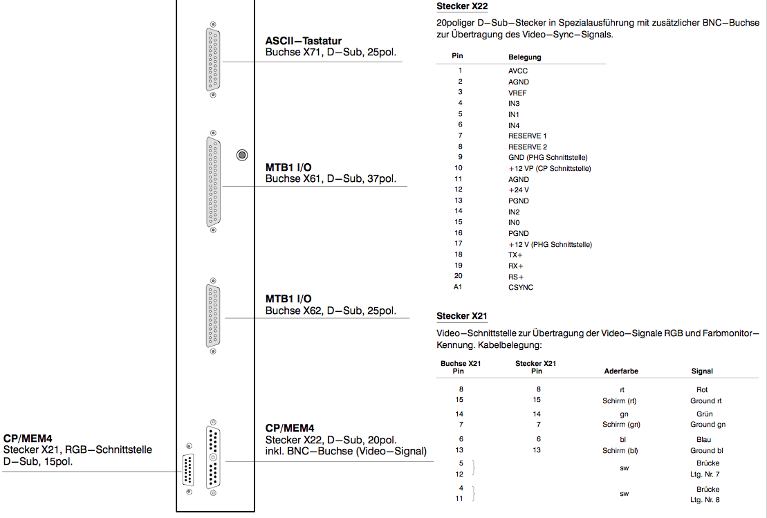
Steuerung noch einen zusätzlichen Stecker, aus dem laut Handbuch
zusätzlich RGB getrennt rauskommen. Bis lang konnte ich da allerdings
nix sinnvolles messen, möglicherweise muss das Signal dort er aktiviert
werden.

Gibt es eine Kombination aus BAS (1-Kanal) und RGB Signalen?
waflija schrieb:> Gibt es eine Kombination aus BAS (1-Kanal) und RGB Signalen?
Kein übliches Standard Signal, aber es ist möglich, aus dem BAS nur
S zu verwenden, um den Monitor zu synchronisieren, und dann die RGB
Kanäle auf die Eingänge des Monitors zu legen.
Einen Multisync könnte man so betreiben, das man z.B. mit einem LM1881
die Sync Signale aus BAS gewinnt. Dr LM1881 kann allerdings nur
zuverlässig auf PAL und NTSC komapatibles Timing synchronisieren. (Für
die Korinthenkacker - ja die heissen eigentlich CCIR und RS-170)
@easylife - Ich zahl aber garantiert keine 5000€ für nen Fernseher mit
BAS Eingang wo hinten einer mit nem Eding "Industrie" oder "CNC" drauf
geschrieben hat.

(Abgesehen davon hat das ganze meine Neugier geweckt)

Ich habe gerade mal einen Fernseher angeschlossen: Es ist definitiv ein
Video (BAS) Signal. Allerdings habe scheint das Signal nicht ganz
"sauber" zu sein, es sind ziemlich massive Bildfehler drauf. Vielleicht
auch ein timing Problem.

Der LM1881 ist ein guter tipp. So sollte das funktionieren. Vielleicht
komme ich so auch direkt auf nen VGA kompatibles RGBHV Signal.
Dem Bild nach zu Urteilen habe ein interlacing Problem. Der Beamer den
ich zu testen benutze scheint das nicht (richtig) zu können. Man sieht
die Halbbilder zwar, aber das ganze ist völlig verschoben gegeneinander.
Wenn du ein Oszi mit TV Trigger hast, schau dir mal den Beginn des VSync
an. Da sollte man, wenns ganz normgerecht ist, im VSignal noch
'Trabanten' sehen, die dafür sorgen, das der HSync währendessen nicht
aus dem Tritt gerät.

Der LM1881 hat auch einen Even/Odd Ausgang, der Interlace/Non-interlace
erkennt. Bei Interlace kommt dann ein 25Hz Rechteck aus diesem Pin. Bei
progressive (non-interlace) passiert da nichts.

Timing ist auch im HSync interessant. Bei genau 64µs Länge einer Zeile
kann man von CCIR ausgehen.
waflija schrieb:> Ich habe gerade mal einen Fernseher angeschlossen: Es ist definitiv ein> Video (BAS) Signal. Allerdings habe scheint das Signal nicht ganz> "sauber" zu sein, es sind ziemlich massive Bildfehler drauf. Vielleicht> auch ein timing Problem.
TV Geräte benutzen das Zeilensprungverfahren zur besseren Darstellung
bewegter Bilder, Computermonitoren schreiben idR Vollbilder das ist für
Text/Graphikdarstellung besser, daher die 'Bildfehler'.
Zu DOS-Zeiten unterschieden sich die Videonormen für PCs durch die
Polarität der Synchronimpulse. Anscheinend sollten Multinorm - Monitore
damit ihre Frequenzen einstellen.
waflija schrieb:> @easylife - Ich zahl aber garantiert keine 5000€ für nen Fernseher mit> BAS Eingang wo hinten einer mit nem Eding "Industrie" oder "CNC" drauf> geschrieben hat.
Du kannst ja mal 20 Euro investieren und Dir auf ebay einen von diesen
GBS-8200 CGA_to_VGA_HD-Converter holen. Die fressen so ziemlich jedes
Videotiming und machen ein VESA-Signal für einen normalen TFT-Bildschirm
draus.
Einfach RGB an RGB und BAS/CVBS als Composite Sync nehmen. Verschiedene
Kombinationen ausprobieren, kaputtgehen kann da nichts.
So einfach funktioniert das leider nicht. Schon probiert :) Ich fürchte
da muss entweder noch eine art Freigabe für die RGB Signale geklemmt
werden oder der GBS 8220 frisst das BAS als CSYNC nicht
Vielleicht sind die 2 Brücken an X21 notwendig, um das RGB Signal zu
aktivieren (siehe Anhang).

Quelle: google mal nach "bosch 1070073300_13.pdf"


Update:

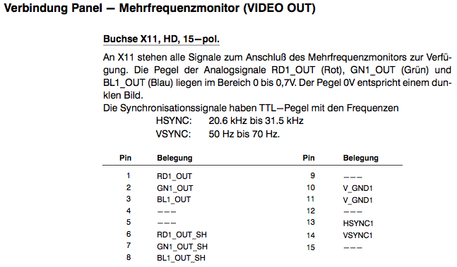
Bzw. sollten an der Buchse X11 auch die SYNC Signale vorhanden sein.
Ich kenne dein Gerät nicht, kann gut sein, dass die Buchse X11 aus dem
ursprünglichen Farb-Bedienteil herauskam.

Was du noch versuchen könntest, ist das CSYNC (composite sync) Signal,
das auf der BNC Buchse liegt, auf den HSYNC Eingang des Beamers oder
Computer-Monitors zu geben. Manche Monitore akzeptieren wohl auch ein
CSYNC Signal auf HSYNC.
Weder der neuere Beamer als auch der alte EIZO Röhrenmonitor frisst es.
Und der EIZO frisst sonst fast alles über BNC. Ich fürchte die kommen
mit den Graustufendaten auf dem CSYNC nicht klar. Werde mal ein LM1881
bestellen und nächstes WE testen.
Hast du mal die 2 Brücken an X21 probiert?
Evtl. haben die ja auch Einfluss auf das Signal auf der BNC Buchse.

So wie ich das aus dem PDF lese, kann man auch ein Monochom Panel
anschließen.
Dieses wird ausschließlich über die BNC Buchse mit Video versorgt (also
Sync + Video), an X21 ist dann nichts angeschlossen (also auch keine
Brücken).
Ich vermute mal, sobald die 2 Brücken an X21 detektiert werden, wirft
die BNC Buchse nur noch das Sync Signal aus, da das Gerät weiss, es ist
ein Farb-Panel angeschlossen.
Die Brücken scheinen nichts zu bewirken.

Neues:
Der LM1881 funktioniert und liefert ein ca. 21kHz CSync (HSync) der VGA
TFT erkennt das zwar, sagt aber "Out of Range". Ist auch irgendwie klar,
VGA hat ja ca. 31khz Sync.
Das Signal is definitiv ein Halbbild signal (Interlaced).
Der GBS-8200 sagt nach wie vor "No Signal" auch mit dem Csync nach dem
LM1881
Habe jetzt hier noch einen 08/15 FBAS zu VGA converter und schau mal ob
der wenigstens das Videosignal S/W frisst. Das sollte ja kein großes
Ding sein.
Neuerer TFT (Eizo S2001) dran, der sagt zwar Signalfehler, stellt es
aber trotzdem dar. Leider bis jetzt nur der Rot Kanal. Scheint aber der
richtige Weg.
Matthias S. schrieb:> waflija schrieb:>> liefert ein ca. 21kHz CSync (HSync)>> Ich wage es kaum auszusprechen, aber das klingt verdammt nach EGA, einem> alten IBM Quasi-Standard, der kurz mal ab 1984 bis etwa 1990 in Mode> war.> https://de.wikipedia.org/wiki/Enhanced_Graphics_Adapter
Aber ein EGA Signal müsste doch eine Beschriftung wie Rot / MSB, Rot /
LSB aufweisen und auf beiden Kanälen ein Signal anliegen?
Ich habe Rot Signal und Schirm und auf dem Roten ist ein Analoges
Signal.
waflija schrieb:> Aber ein EGA Signal müsste doch eine Beschriftung wie Rot / MSB, Rot /> LSB aufweisen und auf beiden Kanälen ein Signal anliegen?
Jaja, ist schon richtig, aber wer sagt, das Bosch sich an sowas hält.
Ich bezog mich vor allem aufs Timing, denn 21kHz sind nun mal weit weg
von CGA (15kHz), MDA/Hercules(18kHz) und VGA (31kHz). Das einzige, was
da so ungefähr in der Nähe ist, ist EGA.
Warum Bosch sowas macht, kann ich dir nicht sagen.
Matthias S. schrieb:> waflija schrieb:>> Aber ein EGA Signal müsste doch eine Beschriftung wie Rot / MSB, Rot />> LSB aufweisen und auf beiden Kanälen ein Signal anliegen?>> Jaja, ist schon richtig, aber wer sagt, das Bosch sich an sowas hält.> Ich bezog mich vor allem aufs Timing, denn 21kHz sind nun mal weit weg> von CGA (15kHz), MDA/Hercules(18kHz) und VGA (31kHz). Das einzige, was> da so ungefähr in der Nähe ist, ist EGA.> Warum Bosch sowas macht, kann ich dir nicht sagen.
Also wenn ich den Sync mit dem LM1881 splitte und das Rot vom X21 Signal
auf R, G und B von Eizo TFT legen, habe ich genau das Bild vom alten CRT
auf dem Schirm. Der Orginal CRT hat scheinbar eine Auflösung von ca.
480x360. Daher 21khz bei etwas weniger als 50Hz refresh. Diesen VGA Modi
unterstützen neue Modi allerdings nicht (mehr).
So weit ich das jetzt reverse-engineered habe wird das Rot Signal auf
den combined Sync Aufmoduliert. Wenn ich einen VGA Monitor an X21 / Rot
anklemme wird das Bild auf dem CRT schwächer, obwohl der über das
kombinierte Signal an X22 angeschlossen ist. - B und G am X21 liefern
eine "schwarz" Linie... Vermutlich ist in der installierten Software
kein Farbmonitor vorgesehen.
-> Ich suche jetzt also eine Lösung um das Signal zu skalieren (VGA
20.6khz (laut Eizo TFT) nach 31+khz.
-> Alternativ einen TFT (auch gerne klein) der low-scan kann, sprich
auch Signale unter 24 khz (Das untere Limit von den meisten Eizo TFTs)
interpretieren kann.
Hi,

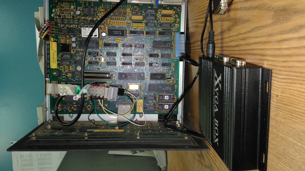
I will try to use the GBS8219 to grab the video signal and display it on
the LCD monitor. I just need help in identifying the video signal source
inside the enclosure. The way I am thinking is that the white ribbon
cable carries the signal, would the pin assignment be the same as posted
earlier; 1-red, 2-green, 3-blue, 10-ground, 13-hsync, 14-vsync. Any help
would be appreciated.

Wally.
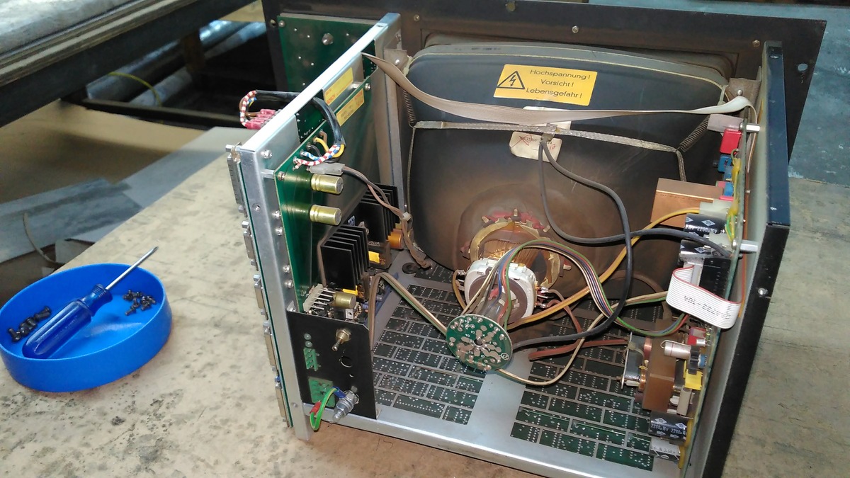
Wally schrieb:> The way I am thinking is that the white ribbon> cable carries the signal, would the pin assignment be the same as posted> earlier; 1-red, 2-green, 3-blue, 10-ground, 13-hsync, 14-vsync
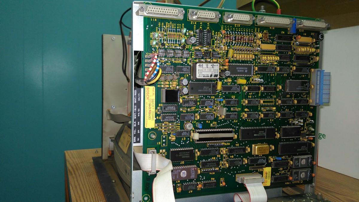
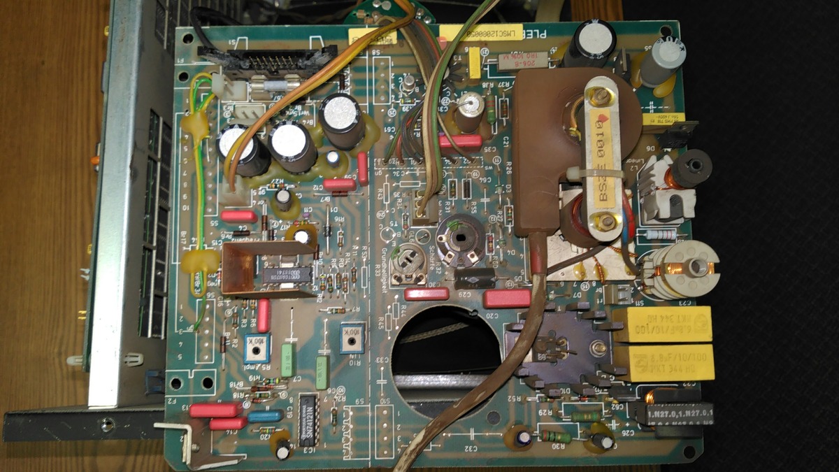
Probably the white ribbon does indeed carry the signals, but the pinning
is unknown. You need to dismount the right board (signal, deflection and
HV) from the monitor seen in picture IMG_20161223_144105.jpg and check
the traces coming from the ribbon connector on that board with an
oscilloscope or at least provide us with good photos of that board from
both sides so that we can help you in identifying the pinout.
You have a much older Trumagraph than Myself. I guess it from the 1980s
or early 1990s right?

On the Picture -4105 I can see the input connectors on the left. Could
take a details photo of them? For the newer Trumagraph Assembly one of
them should have a BNC connector in the middle. It connects the PLC in
the switching cabinet to the button / monitor assembly. This BNC Wire
carries a combined sync / gray signal. This signal can be split by the
LM1881 into to seperate signals. (which are recognized by my EIZO
Monitor, but I did not find a way to scale this signal to a supported
VGA mode on todays monitors.)
From there you could trace the signal to the monitors PCB.

If you are lucky there may be a second connector with seperated R-G-B
Channels. At least on my 1998 Trumatic 500R with Bosch PLC this
connector is present. Otherwise you hav to install a little Board with
an LM1881 and some other parts, the schematic can be found in the LM1881
datasheet.

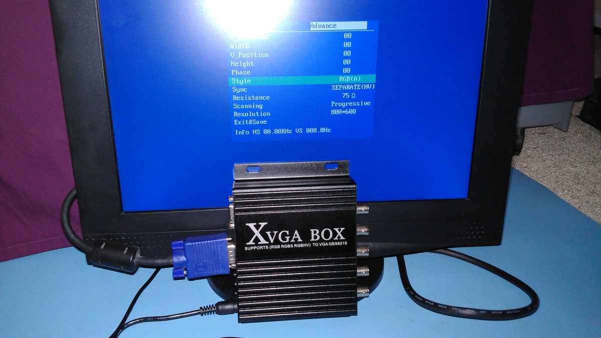
By the way, according to the specifications in the ebay listing this
XVGA box could be a solution to scale my signal. At least on the package
is says "12-30khz Hsync input", which should work for me.
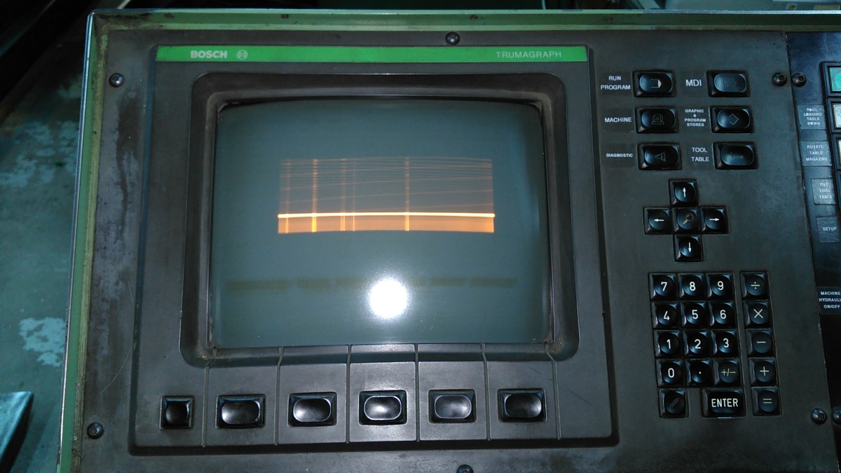
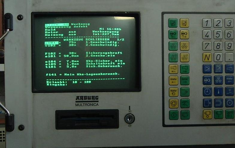
OXI T. schrieb:> Falls jemand im Raum Solingen mal diesen Fehler> am Monitor hat,
Das Ding ist bei den Trumagraph meist nicht nur so ein Fehler. Du siehst
auf den Fotos schon sehr schön die eingebrannte Maske. Abgesehen davon
sind die Dinger nach 15 oder sogar 25 Jahren Dauerbetrieb auch mit
Helligkeit und Kontrast total am Ende. Da hilft nur tauschen, aber das
ist halt dank des Bosch-Eigenbau Signals nicht so einfach.
waflija schrieb:> Abgesehen davon> sind die Dinger nach 15 oder sogar 25 Jahren Dauerbetrieb auch mit> Helligkeit und Kontrast total am Ende. Da hilft nur tauschen
Offensichtlich hast Du noch keinen reparierten
Monitor gesehen.
LG
old.
Also da will ich sehen wie du für ca. 400€ (GB8219 + Monitor) die
eingebrannte Maske wieder rausbekommst und die Helligkeit
wiederherstellst. :D Wenn das für den Preis machbar ist, darfste gerne
vorbei kommen.

PS: Wenn du dem netten Herren auf englisch schreibst, antwortet er dir
vielleicht. Immerhin hat er gerade genau das Problem.
waflija schrieb:> Also da will ich sehen wie du für ca. 400€
Die Reparatur wird keine 400€ kosten.
Muss da ja werder die Bildröhre noch den Zeilentrafo
wechseln.
Die Einbrenner stören auch nicht weiter da sie die
Lesbarkeit nicht beeinträchtigen.
Bild: Ein reparierter monochrom-Monitor.
LG
old.
Glaub mir, die Maske stört sobald du in ein anderes Menü oder gar die
graphische Programmierung von Trumpf wechselst. An den "Flecken" siehst
du dann kaum etwas. Einer der Gründe warum ich meinen tauschen will.
waflija schrieb:> Das Ding ist bei den Trumagraph meist nicht nur so ein Fehler. Du siehst> auf den Fotos schon sehr schön die eingebrannte Maske.
Und Du bist sicher, dass da nicht eine stinknormale 12"-Bildröhre drin
ist? Die tauschst Du gegen eine von einem Homecomputer-Monitor für 10
Euro von Ebay. Ich bevorzuge die vom Atari SM-124, ein sehr schöner
Weisston mit entspiegelter Oberfläche.
soul e. schrieb:> Und Du bist sicher, dass da nicht eine stinknormale 12"-Bildröhre drin> ist? Die tauschst Du gegen eine von einem Homecomputer-Monitor für 10> Euro von Ebay. Ich bevorzuge die vom Atari SM-124, ein sehr schöner> Weisston mit entspiegelter Oberfläche.
Das ist tatsächlich keine schlechte Idee. Davon habe ich allerdings
recht wenig Ahnung und bin daher nicht drauf gekommen. - Die Röhre sieht
man ja auf den Fotos von Wally, ist das eine Standardröhre? Dann würde
ich tatsächlich mal nach nem alten CRT als Alternative ausschau halten.
waflija schrieb:> Das ist tatsächlich keine schlechte Idee. Davon habe ich allerdings> recht wenig Ahnung und bin daher nicht drauf gekommen. - Die Röhre sieht> man ja auf den Fotos von Wally, ist das eine Standardröhre? Dann würde> ich tatsächlich mal nach nem alten CRT als Alternative ausschau halten.
Fast alle 12"-Monochromröhren habe 12 V Heizspannung und 13 kV
Nachbeschleunigung. Pin 3+4 ist Heizung, 2 Kathode, 1 G1 (Helligkeit), 6
G2 (Screen), 7 G3 (Focus).
An Kathode und G1 sind unter 100 V, an G2 600 V, an G3 bis zu 300 V. Das
kann man mit einem vernünfigen Multimeter nachmessen, oder einfach per
Auge die Leitungen zu den Potis verfolgen.
An der Hochspannung gibt es nichts zu messen. Auch die dafür
vorgesehenen HV-Tastköpfe beeinflussen das Messergebnis, da muss man
sein Werkzeug gut kennen um das Ergebnis bewerten zu können. Der
HV-Kreis hat nicht viel Energie, zwickt aber ordentlich. Die primäre
Gefahr besteht daher darin, zu erschrecken und etwas fallen zu lassen
oder irgendwo reinzuschlagen. Daher vor dem Abstecken des HV-Kabels die
Hochspannung über ein paar in Reihe geschaltete Widerstände abfliessen
lassen. Die Energie steckt in der Röhre, nicht im Trafo. Die Röhre ist
ein Kondensator, und dessen Ladung kann nach einer Weile wiederkommen
(Maxwell-Wagner Relaxation / dielektrische Absorption), daher für eine
längere Zeit kurzschließen oder einfach die Finger vom Loch lassen.
Im Gegensatz zu den Röhren können die Ablenkspulensätze deutlich
unterschiedlich sein. Daher am besten den alten Spulensatz auf die neue
Röhre montieren. Geometrie einstellen geht einfacher als man denkt: erst
Spule drehen bis das Bild gerade ist, dann mit den beiden Hebelchen die
Ecken auseinanderziehen, und zu guter Letzt mit den kleinen Magneten
aussen am Plastikrand die Kanten glätten.
Hello Everyone,
Thanks for all the information so far.
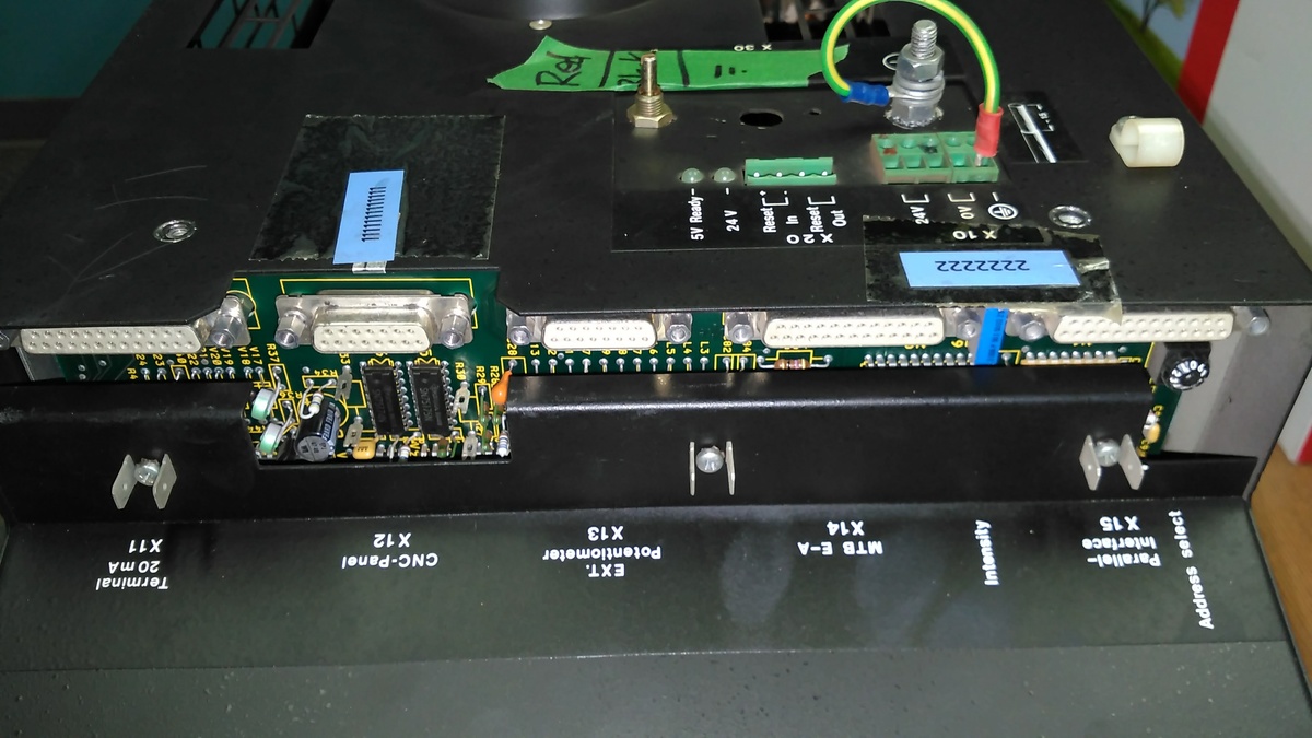
I took a few more pictures of the Bosch CC300, it’s controlling the
TC240R built in 1989. There are no other video connections that I could
identify – keep in mind that I am no video output expert.
On the input side of the controller we use 4 connections: X11 for
sending programs, X12 connection to the PLC cabinet, X13 for motion
speed control and X10 for power supply.
We looked into a Trumpf refurbished unit but the cost is $4000 US. I
have found a number of online vendors in UK, Germany and China that are
selling replacement Bosch CC300 monitors starting at $550 US but once
again even though I am not an electronics guy I like the challenge of
getting it fixed myself (hopefully with your help) – as most of the
Chinese units look like they are using the GBS8219.
If I could get the GBS8219 to display the info on the LCD monitor that
would mean a few more years of production for the punch press at a next
to nothing repair cost. If you search the ebay.com for: “GBS-8219 XVGA
Box CGA/EGA/RGB/RGBS/RGBHV/VGA Industrial Monitor Video Converter”, you
should be able to find seller: eshow.b2c that sells this converter for
~$150 US, shipping included.
Thanks for allowing me to communicate with you in English, I couldn’t
find any other forums discussing the subject of Bosch controller video
display. Also, sorry for the delay in my replies, I live in Canada which
puts me 6 hrs. behind your time zone.
Regards,
Wally
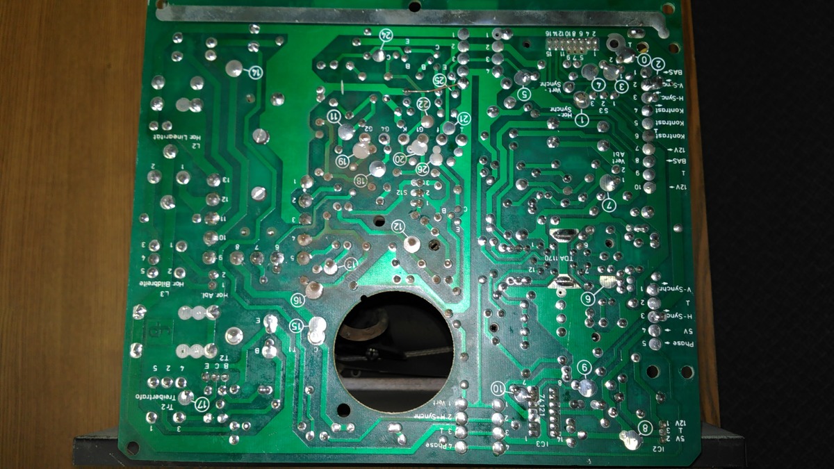
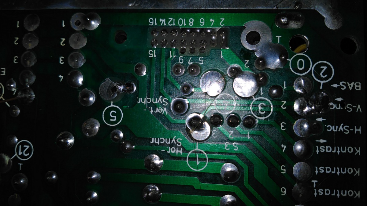
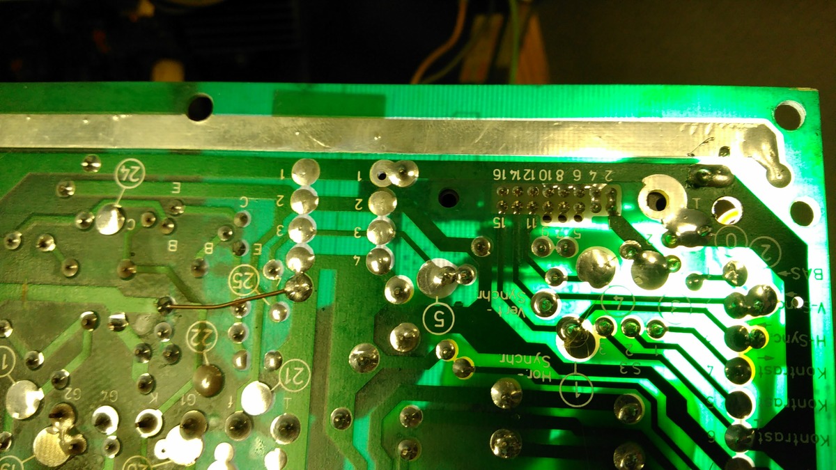
Wally schrieb:> IMG_20170103_113534.jpg
That does look good and whats even better, most of the pins you'll need
have a printed description. You'll need the Hor. Sync. Signal from Pin
15 of the ribbon connector, the Vert. Sync. which comes probably from
Pin 13 and the BAS Signal which is hard to see in the picture but
probably easy to trace on the PCB.
The Sync. signals correspond to the same pins on the VGA Input connector
of your scaler box while BAS should be connected either to the green
video input only (yielding an all-green video on screen) or better to
all three inputs (R,G and B) for a white on black picture.
Don't forget the ground connection from the point designated with the
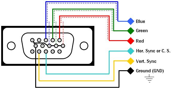
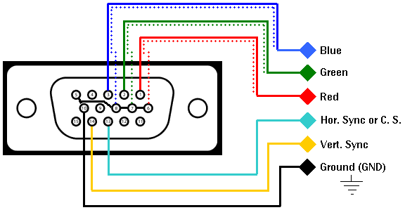
'0' and the ground symbol to your VGA input. It seems as if the ribbon
cable uses all even numbered pins for ground. Use the 'vga2arcade.gif'
picture as a reference to route the GND pins.
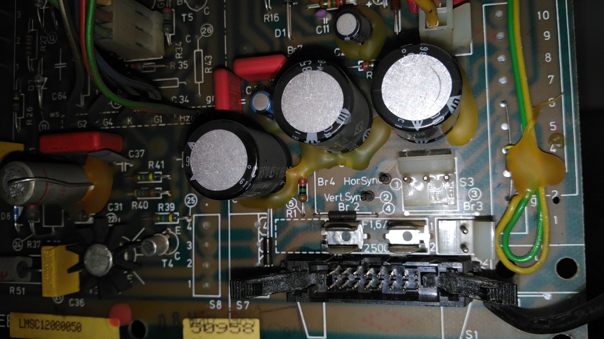
Check if you have a picture and if that is so you can disconnect the old
monitor and remove it from the frame.
From its symptons i'd say theres a problem with its power supply which
seems to be much too low. Could be a simple as a bad fuseholder, but
don't qquote me on that :-)
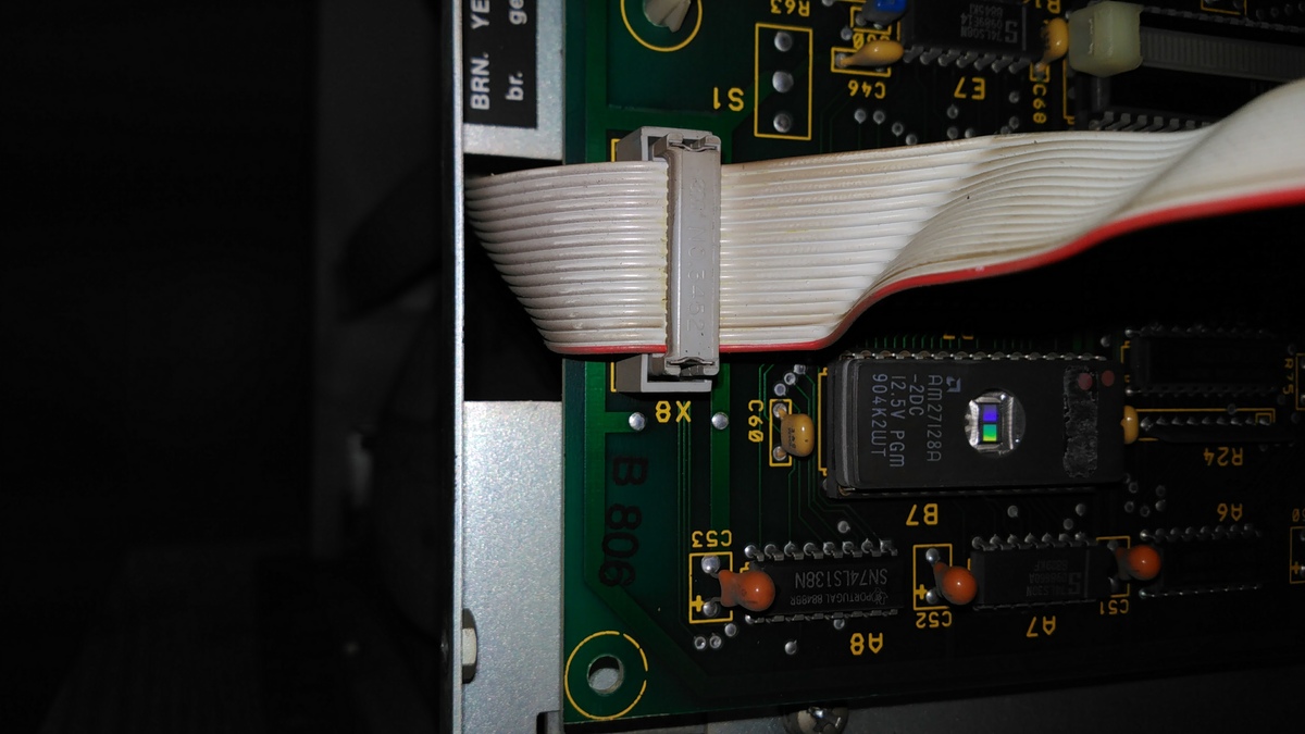
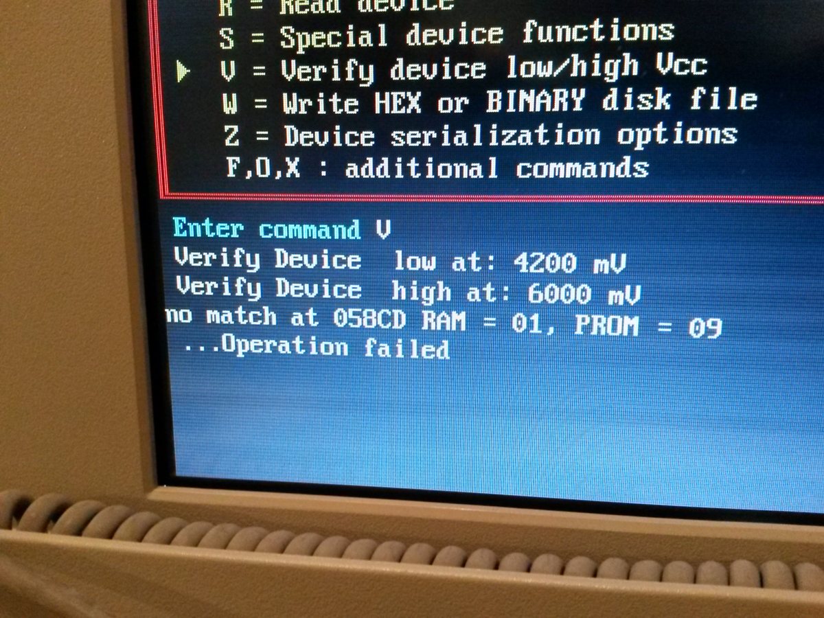
Oh, on another note, your machine is controlled through old EPROM chips
which are due to fail after 25-35 years of operation. It would be a good
idea to read them out and copy the contents to a new EPROM as long as
the machine is still operable.
Chip B7 is one of them (its from 1990) and there are two more from Texas
Instruments in the other corner of the control board.
@Wally
You helped me a lot to finding the GB8219 - Myself I just found the
GB8220 / GB8200 which do not work.

The Video-Signal is definatly located in the X12. It seems that this
older model does not use a shielded connection.
But on the -534 Picture I can see soldering pads labled "BAS", which is
German for "VBS", a specific video standard. Usually found on devices as
BNC or yellow chinch connector. (Sometime just called "Video") According
to the little Arrow try to check if Pad "1 <- BAS" is connected to on of
the pins in you connector. PIN 2 and 3 are the sync signals, but with a
proper VBS / BAS Signal they may not be connected. With a bit of luck,
they did just use a standard VBS signal, which could be used directly.

According to the picture the BAS Pad is connected to PIN 1 of the
black-connector. (Which was used internally, right?) Try to find a
ground in there and connect GND / BAS to a chinch connector (BAS on the
"pin" and GND on the Ring)

From there the easiest thing would be to get an old, TV with an VBS
input, preferably from some brand manufacturer and hook it up to BAS /
GND. A TV from a good brand may have a much better input filtering and
range. If a flat-TV does not work, try a CRT TV. They work on a even
wider frequency range. If you get some kind a picture with half the
lines missing or misplaced parts of the picture try to switch
"interlacing mode" on your TV device.

Switch on the PLC, but do not connect the old monitor. (Just make sure
the Power Supply for the tube etc is disconnected to be safe) With a bit
luck you should get a picture on the TV, now :)

PS: I found the chinese monitor, too but did not buy one. My guess was
they did not really now which machine their monitors fit and allways say
it will work to sell it. I sent them some Machine names I totally made
up, like an Trump 510L and they tried to sell me "100% working"
replacement for it. - And of course they had replaced monitors in the
Trumpf 510L before...

PPS: The TFT-conversion kit from Trumpf itself for the 500R is about
12.000€. Kind of a rip-off for a simple 300€ 12" TFT and a maybe 400€
converter.
Matthias S. schrieb:> Oh, on another note, your machine is controlled through old EPROM chips> which are due to fail after 25-35 years of operation. It would be a good> idea to read them out and copy the contents to a new EPROM as long as> the machine is still operable.
Hey, da warst du etwas schneller als ich mit der Antwort :)
Die frage ist, ob sich das Auslesen und das finden von Ersatz für die
EPROMs noch lohnt. Die SPS dadrin hat 20-30 Stück davon. Immerhin will
der damit Geld verdienen und es ist kein Liebhaberstück.
waflija schrieb:> Die frage ist, ob sich das Auslesen und das finden von Ersatz für die> EPROMs noch lohnt.
Das kann ich natürlich nicht beurteilen - ich weiss nur, das wir in den
letzten Jahren mit EPROMs in Boards von Ende der 80er bis Mitte der 90er
enorme Probleme mit Datenverlust hatten.
Es kommt darauf an, wie die Dinger damals gebrannt wurden. Solche, die
mit 'intelligenten' Algorithmen gemacht wurden, scheinen die Daten lange
nicht so gut zu halten, wie die mit sturen 50ms Pulsen gebrannten.
Für die betroffenen Boards (bei uns sinds Car Controller von Kewet) habe
ich deswegen extra wieder EPROM Brenner und Files gemacht.
Matthias S. schrieb:> Für die betroffenen Boards (bei uns sinds Car Controller von Kewet) habe> ich deswegen extra wieder EPROM Brenner und Files gemacht.
Interessant, aber bekommt da überhaupt noch etwas kompatibles für die
uralten Dinger? Oder eicht auslesen + neu brennen?
waflija schrieb:> Interessant, aber bekommt da überhaupt noch etwas kompatibles für die> uralten Dinger?
Man bekommt fast alles noch NOS, zu entsprechenden Preisen.
> Oder eicht auslesen + neu brennen?
Reicht fast immer.
waflija schrieb:> Interessant, aber bekommt da überhaupt noch etwas kompatibles für die> uralten Dinger?
Rom ist Rom - ein 2764 oder 27256 durch einen Adapter und ein Flash-Rom
im PLCC zu ersetzen ist auch kein Hexenwerk. Muss nur 5V-tolerabel sein.
Georg
waflija schrieb:> Interessant, aber bekommt da überhaupt noch etwas kompatibles für die> uralten Dinger? Oder eicht auslesen + neu brennen?
Auslesen und neu brennen. Ohne zu löschen einfach drüberbrennen. Und
natürlich ein Backup machen und irgendwo hochladen, so dass auch die
anderen was davon haben.
So bin ich gerade an ein Keithley 2000 gekommen. Nach dem Einschalten
hat das Ding gepiept, alle Segmente im Display angemacht, und das war's.
Ein Bitkipper im unteren EPROM. Auslesen mit 100 kHz im EPROMMer und
Verify gegen das von Keithley freundlicherweise zur Verfügung gestellte
Image war noch okay, Auslesen im Betrieb bei 4 MHz durch den 68000er
aber nicht mehr.
Wenn EPROMs ihre Ladung verlieren, werden sie langsamer. Und in den
meisten Fällen (bei den Typen die "leer" 0xFF enthalten) liest man
besser bei etwas niedrigerer Betriebsspannung.
waflija schrieb:> Interessant, aber bekommt da überhaupt noch etwas kompatibles für die> uralten Dinger?
Ich habe noch nagelneue im Schubfach. Wenn die nicht reichen, muss der
Kunde halt etwas mehr bluten.
Hello Everyone,

Matthias and waflija, thanks a lot for your input in helping me get the
video signal out the LCD monitor.
All I could do was to check the circuit board with the multimeter and
shine some light to see the routing. This is what I managed to identify:
pin 1 and 2       - power supply
pins 3 4 6 8 10 12 14 16   - ground
pins 5 7 9       - doesn’t look like they are used
pin 11        - video signal
pin 13        - V Sync
pin 15        - H Sync

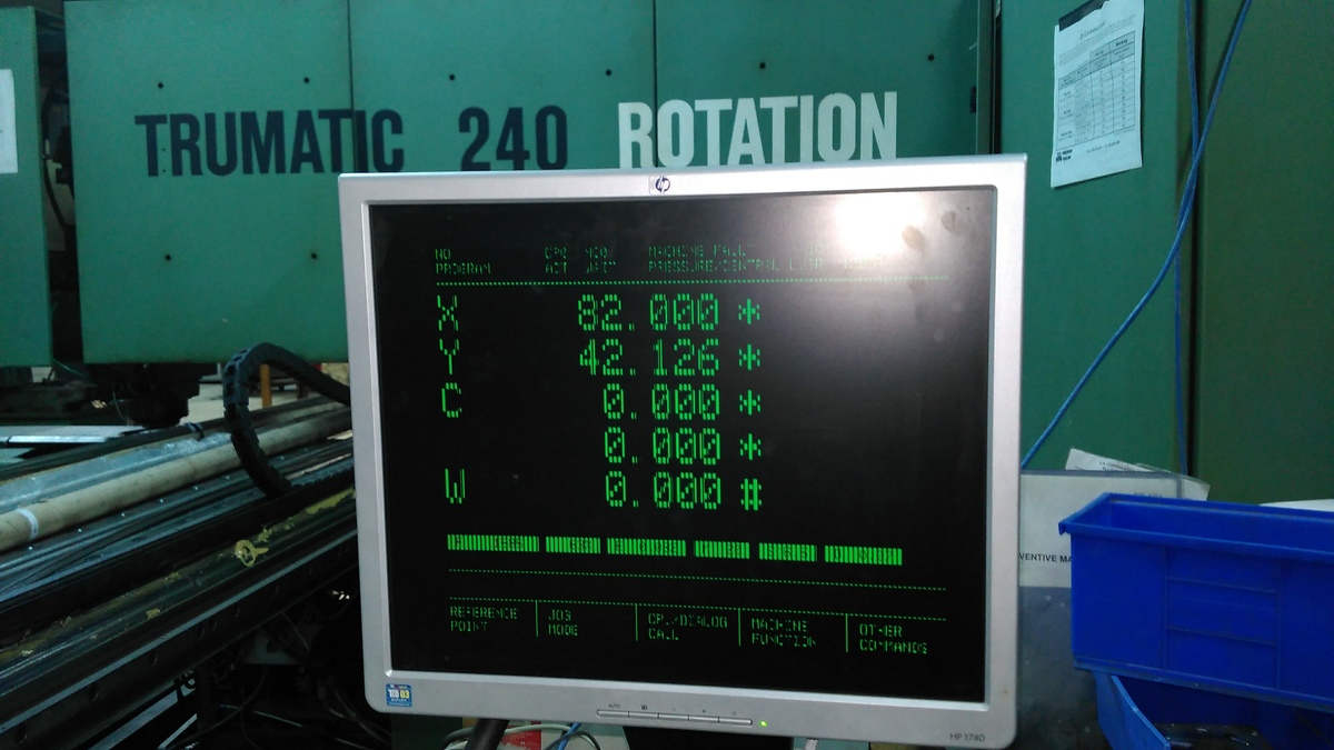
I get video to display on the monitor but it’s not very crisp. The
machine started up and referenced without any problems so we are good to
go. Now that I know how to get the video I will do the following to
hopefully get a better picture:
•  check the GBS8219 manual for any other possible adjustments
•  make a better cable to go from X8 to the GBS8219
•  connect the BAS video signal to all three input R, G, B wires for the
black on white display
•  find an LCD monitor (10.4” ideally to fit into the existing opening)
with a native 800 X 600 display resolution as the current one is
complaining that it’s running at the wrong value
If you could think of anything else, please let me know.
Now I just have to look into getting the EPROMS backed up and
reprogrammed.
Once again, thanks for all your help.
Regards,
Wally
Off topic: Nice :) An 240R still in production they are getting pretty
rare around here. We just scrapped our old 180L, because it was just to
costly to maintain after 30 years.

On Topic: This picture looks like interlacing problems.
https://en.wikipedia.org/wiki/Interlaced_video

Please keep in Mind, that BAS / VBS is most likely NOT a RGB Signal like
it would be used in a VGA connector. - Even if Sync is present as
seperate signal. Because this machine is German and most of the parts
are made / labled in German I would guess they used the German PAL-Video
standard. Maybe you could try to configure the converter to PAL Mode
with interlacing and see what happens.
If you can see what input resolution the converter detects you could
check my if this is something like 640x480 (VGA) or something odd like
625x576 or 525x480 (Which would be PAL)

More info on VBS:
https://en.wikipedia.org/wiki/Composite_video
waflija schrieb:> On Topic: This picture looks like interlacing problems.> https://en.wikipedia.org/wiki/Interlaced_video
Interlace is easily identified by looking at the frame rate. A standard
625-line (CCIR-System B also called 576i) Signal inserts a 50Hz (20ms)
V-Sync while a non-interlaced 576p (progressive) signal would use a 25Hz
(40ms) V-Sync.
But none of these signal definitions fit with your experience, as a
800*600 Signal is not possible with any of the PAL/CCIR-B/576i formats.
As the name says, a 576i signal would have 576 visible lines while the
rest are wasted in the vertical blanking, adding up to 625 lines.
As your monitor says it has detected a 21kHz H-Sync and 50Hz V-Sync
which doesn't match up with any well known standard.
From what i guess, Bosch did expand the 576i Standard to 600 while
maintaining the frame rate of 50Hz. They needed to increase H-Sync to 21
kHz for all the 600 visible lines to fit into a 50Hz frame.
Wally schrieb:> • connect the BAS video signal to all three input R, G, B wires for the> black on white display
Sounds goods - you should try that first.
> • find an LCD monitor (10.4” ideally to fit into the existing opening)> with a native 800 X 600 display resolution as the current one is> complaining that it’s running at the wrong value
Even better. Its probably not easy to be found, though.
waflija schrieb:> Ich habe gerade mal einen Fernseher angeschlossen: Es ist definitiv ein> Video (BAS) Signal. Allerdings habe scheint das Signal nicht ganz> "sauber" zu sein, es sind ziemlich massive Bildfehler drauf. Vielleicht> auch ein timing Problem.
Hi waflijah,
ich hab etwas ähnliches gemacht:
Beitrag "Röhrenfernseher mit RGB&sync over SCART durch welchen Fernseher (TFT) ersetzen?"
Bei mir war es aber RGB&S das ich mit SCART auf nen Fernseher gebracht
habe.
Interessannt ist, das "grün" (oder war es rot?) sogar Componentvideo
hatte und als PAL oder NTSC durchging!
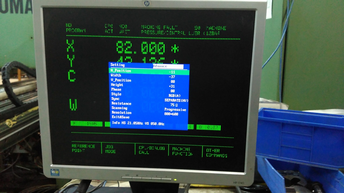
Are the values shown in the picture the output of the converter or the
Monitor itself?
> As your monitor says it has detected a 21kHz H-Sync and 50Hz V-Sync> which doesn't match up with any well known standard.
If this is this picture shows the input of the converter from the PLC:
That was my latest guess with my machine, too. The "Bosch" signal is
just losely based on the PAL standard. I got the same wired 21khz signal
with a 10 Years newer PLC.
Matthias S. schrieb:>> • find an LCD monitor (10.4” ideally to fit into the existing opening)>> with a native 800 X 600 display resolution as the current one is>> complaining that it’s running at the wrong value>> Even better. Its probably not easy to be found, though.
Maybe you can change the output of the converter to another resolution?
From what I read in the description it should be able to output up to
1600x1200 with standard VGA timings.
Alex W. schrieb:> Interessannt ist, das "grün" (oder war es rot?) sogar Componentvideo> hatte und als PAL oder NTSC durchging!
Du hattest mit dem Gerät aber nicht Bosch mit seinem "not invented here"
Syndrom. Das Prinzip nennt sich übrigens "Sync over green" und ja, dann
kann man Grün als BAS/VBS Signal für S/W nehmen.
Glück gehabt, der Hersteller hat sich damals an den Standard gehalten.
Bosch tut das scheinbar nicht. Warum auch bei einer 600.000 DM Maschine?
Ich könnt mich da jetzt Stundenlang drüber aufregen
Alex W. schrieb:> ich hab etwas ähnliches gemacht:> Beitrag "Röhrenfernseher mit RGB&sync over SCART durch welchen Fernseher> (TFT) ersetzen?">> Bei mir war es aber RGB&S das ich mit SCART auf nen Fernseher gebracht> habe.
Nope - du hattest ein anderes Problem. Du hattest einfach nur vergessen,
das RBG Eintastsignal auf RGB zu setzen. Dieses Signal bewirkt im TV ein
Umschalten vom FBAS Eingang auf die RGB Eingänge und wurde früher oft
dazu benutzt, externe Dekoder wie BTX oder VTX an den Fernseher über das
Videosignal einzutasten (RBG insert).
Heutige SetTop Boxen schalten diese Spannung, wenn man den Videoausgang
von Composite auf RGB umschaltet.
Hier bei diesen Kisten liegt die Problematik darin, das das Timing
proprietär ist mit 21kHz H-Sync und 50Hz V-Sync. Die Scalerkiste ist
damit am Rande dessen, was geht und deswegen lässt sie im Moment alle
paar Pixel einen aus - ihr Antialiasing klappt nicht.
@Wally: Try to tamper with the setting of the GBS Box as waflija
suggested. A multiple of 800 pixel horizontal could convince the box to
do its antialiasing job again and give a better picture without omitting
every 4th pixel or so.
VGA to 576i (and vice versa) is a much easier job because the timing is
roughly a 2:1 ration (31,5kHz to 15,6kHz). But 21kHz to 31,5kHz for VGA
is hard to accomplish for the little scaler box.
What would really help is one of those old NEC Multisync Monitors. I had
a B/W CRT from NEC and ist synced on everything i fed it with. Too bad
todays displays are mostly fixed on the established standards.
waflija schrieb:> Ich könnt mich da jetzt Stundenlang drüber aufregen
Und ich sitze hier kopfschüttelnd weil Ihr den
Originalmonitor nicht repariert haben wollt.
Alle Standarts zwischen TV und VGA sind für
Flachmänner problematisch.
LG
old.
OXI T. schrieb:> Und ich sitze hier kopfschüttelnd weil Ihr den> Originalmonitor nicht repariert haben wollt.
Naja, die meisten jüngeren Leute legen sich heute die Karten bei CRTs
und deren Eigenheiten. Wir alten Knacker würden die Kiste vermutlich in
ein, zwei Stunden wieder am Laufen haben, aber so ist die Jugend heute
eben :-)
Und es werden eben auch Horrorstories über gefährliche Spannungen und
'alles tödlich' verbreitet, was wir schon immer wussten und
berücksichtigt haben.
Das können die aber nicht mehr, weil ihnen die Grundlagen fehlen. CRT
war eben in der 'Vor-Internet-Zeit' und ist deswegen schwieriger zu
recherchieren und die alten Knacker schreiben auch nichts mehr drüber,
weil es die Dinger eben nicht mehr gibt.
Allerdings habe ich mein Bildrohr-Regenerierer immer noch auf Lager, für
den Fall der Fälle :-)
Matthias S. schrieb:> Naja, die meisten jüngeren Leute legen sich heute die Karten bei CRTs> und deren Eigenheiten.
tja wie hat man früher payTV geschaut, (dumdidum.....)
2 TV Seite an Seite Rückwand offen und den vergurkten Syncimpuls vom
payTV einfach ersetzt zu einem aus dem anderen TV.
wie hat man früher den PalEmpfänger für den appleII zu NTSC umgebaut,
ein Palmodul auf 3,58 MHz abgeglichen und den Pal Schalter totgelegt,
das ganze auf eine PAL/Secam Umschaltplatine,
geschaltet von der Uhr Taste auf der FB wo bei meinem eh keine Uhr war,
mit einem Kombi Pal/Secam Modul war der TV dann 3-sprachig..
Joachim B. schrieb:> tja wie hat man früher payTV geschaut, (dumdidum.....)>> 2 TV Seite an Seite Rückwand offen und den vergurkten Syncimpuls vom> payTV einfach ersetzt zu einem aus dem anderen TV.
Teleclub war aber auch zu simpel kodiert. Schon ein Blinder mit
Krückstock ist auf die Verschlüsselung gekommen und wir haben einfach
einen Kombituner für den Sync-Kanal benutzt und damit ein paar PIN
Dioden geschaltet.
Ich hatte mir auch mal einen Dekoder gebaut, der aus den ersten paar
Zeilen den Schwarzpegel rausfischte und danach einen Flipflop umpolte,
der brav vom H-Sync toggelte. Ging nur bei Spielfilmen, weil bei denen
die ersten paar Bildzeilen schwarz waren (war ja alles 4:3). Aber so
isses - Schnee von gestern und Spass hats trotzdem gemacht :-)