1 | /******************************************************************************/
|
2 | /* IRG3200_1.C: GYRO */
|
3 | /*Info: Gyro1 und 2 an I2C-1 und I2C-2; Accel1 und 2 an SPI1 und SP2; */
|
4 | /*Gyro I2C Adresse: bin: 1101000 hex: 0x68 */
|
5 | /******************************************************************************/
|
6 |
|
7 | /* Includes */
|
8 | #include "ITG3200_1.h"
|
9 | #include "stm32f10x.h"
|
10 | #include "misc.h"
|
11 |
|
12 |
|
13 | float gyr_adj[3]={0};//ITG 0-bias
|
14 |
|
15 | /**
|
16 | * @defgroup ITG
|
17 | * @{
|
18 | */
|
19 |
|
20 | /** @defgroup ITG_I2C_Function
|
21 | * @{
|
22 | */
|
23 |
|
24 | /**
|
25 | * @brief Initializes the I2C peripheral used to drive the ITG
|
26 | * @param None
|
27 | * @retval None
|
28 | */
|
29 | void ITG_I2C_Init(void)
|
30 | {
|
31 | I2C_InitTypeDef I2C_InitStructure;
|
32 | GPIO_InitTypeDef GPIO_InitStructure;
|
33 |
|
34 | /* Enable I2C and GPIO clocks */
|
35 | RCC_APB1PeriphClockCmd(ITG_I2C_RCC_Periph, ENABLE);
|
36 | RCC_APB2PeriphClockCmd(ITG_I2C_RCC_Port, ENABLE);
|
37 |
|
38 | /* Configure I2C pins: SCL and SDA */
|
39 | GPIO_InitStructure.GPIO_Pin = ITG_I2C_SCL_Pin | ITG_I2C_SDA_Pin;
|
40 | GPIO_InitStructure.GPIO_Speed = GPIO_Speed_50MHz;
|
41 | GPIO_InitStructure.GPIO_Mode = GPIO_Mode_AF_OD;
|
42 | GPIO_Init(ITG_I2C_Port, &GPIO_InitStructure);
|
43 |
|
44 | /* I2C configuration */
|
45 | I2C_InitStructure.I2C_Mode = I2C_Mode_I2C;
|
46 | I2C_InitStructure.I2C_DutyCycle = I2C_DutyCycle_2;
|
47 | I2C_InitStructure.I2C_OwnAddress1 = 0x00;
|
48 | I2C_InitStructure.I2C_Ack = I2C_Ack_Enable;
|
49 | I2C_InitStructure.I2C_AcknowledgedAddress = I2C_AcknowledgedAddress_7bit;
|
50 | I2C_InitStructure.I2C_ClockSpeed = ITG_I2C_Speed;
|
51 |
|
52 | /* Apply I2C configuration after enabling it */
|
53 | I2C_Init(ITG_I2C, &I2C_InitStructure);
|
54 |
|
55 | /* I2C Peripheral Enable */
|
56 | I2C_Cmd(ITG_I2C, ENABLE);
|
57 | }
|
58 |
|
59 | /**
|
60 | * @brief Writes one byte to the ITG.
|
61 | * @param slAddr : slave address ITG_A_I2C_ADDRESS or ITG_M_I2C_ADDRESS
|
62 | * @param pBuffer : pointer to the buffer containing the data to be written to the ITG.
|
63 | * @param WriteAddr : address of the register in which the data will be written
|
64 | * @retval None
|
65 | */
|
66 | void ITG_I2C_ByteWrite(u8 slAddr, u8* pBuffer, u8 WriteAddr)
|
67 | {
|
68 | /* Send START condition */
|
69 | I2C_GenerateSTART(ITG_I2C, ENABLE);
|
70 |
|
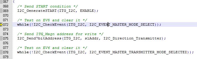
71 | /* Test on EV5 and clear it */
|
72 | while(!I2C_CheckEvent(ITG_I2C, I2C_EVENT_MASTER_MODE_SELECT));
|
73 |
|
74 | /* Send ITG address for write */
|
75 | I2C_Send7bitAddress(ITG_I2C, slAddr, I2C_Direction_Transmitter);
|
76 |
|
77 | /* Test on EV6 and clear it */
|
78 | while(!I2C_CheckEvent(ITG_I2C, I2C_EVENT_MASTER_TRANSMITTER_MODE_SELECTED));
|
79 |
|
80 | /* Send the ITG internal address to write to */
|
81 | I2C_SendData(ITG_I2C, WriteAddr);
|
82 |
|
83 | /* Test on EV8 and clear it */
|
84 | while(!I2C_CheckEvent(ITG_I2C, I2C_EVENT_MASTER_BYTE_TRANSMITTED));
|
85 |
|
86 | /* Send the byte to be written */
|
87 | I2C_SendData(ITG_I2C, *pBuffer);
|
88 |
|
89 | /* Test on EV8 and clear it */
|
90 | while(!I2C_CheckEvent(ITG_I2C, I2C_EVENT_MASTER_BYTE_TRANSMITTED));
|
91 |
|
92 | /* Send STOP condition */
|
93 | I2C_GenerateSTOP(ITG_I2C, ENABLE);
|
94 |
|
95 | }
|
96 |
|
97 | /**
|
98 | * @brief Reads a block of data from the ITG.
|
99 | * @param slAddr : slave address ITG_A_I2C_ADDRESS or ITG_M_I2C_ADDRESS
|
100 | * @param pBuffer : pointer to the buffer that receives the data read from the ITG.
|
101 | * @param ReadAddr : ITG's internal address to read from.
|
102 | * @param NumByteToRead : number of bytes to read from the ITG ( NumByteToRead >1 only for the gyro readinf).
|
103 | * @retval None
|
104 | */
|
105 |
|
106 | void ITG_I2C_BufferRead(u8 slAddr, u8* pBuffer, u8 ReadAddr, u16 NumByteToRead)
|
107 | {
|
108 |
|
109 | /* While the bus is busy */
|
110 | while(I2C_GetFlagStatus(ITG_I2C, I2C_FLAG_BUSY));
|
111 |
|
112 | /* Send START condition */
|
113 | I2C_GenerateSTART(ITG_I2C, ENABLE);
|
114 |
|
115 | /* Test on EV5 and clear it */
|
116 | while(!I2C_CheckEvent(ITG_I2C, I2C_EVENT_MASTER_MODE_SELECT));
|
117 |
|
118 | /* Send ITG_Magn address for write */
|
119 | I2C_Send7bitAddress(ITG_I2C, slAddr, I2C_Direction_Transmitter);
|
120 |
|
121 | /* Test on EV6 and clear it */
|
122 | while(!I2C_CheckEvent(ITG_I2C, I2C_EVENT_MASTER_TRANSMITTER_MODE_SELECTED));
|
123 |
|
124 | /* Clear EV6 by setting again the PE bit */
|
125 | I2C_Cmd(ITG_I2C, ENABLE);
|
126 |
|
127 | /* Send the ITG_Magn's internal address to write to */
|
128 | I2C_SendData(ITG_I2C, ReadAddr);
|
129 |
|
130 | /* Test on EV8 and clear it */
|
131 | while(!I2C_CheckEvent(ITG_I2C, I2C_EVENT_MASTER_BYTE_TRANSMITTED));
|
132 |
|
133 | /* Send STRAT condition a second time */
|
134 | I2C_GenerateSTART(ITG_I2C, ENABLE);
|
135 |
|
136 | /* Test on EV5 and clear it */
|
137 | while(!I2C_CheckEvent(ITG_I2C, I2C_EVENT_MASTER_MODE_SELECT));
|
138 |
|
139 | /* Send ITG address for read */
|
140 | I2C_Send7bitAddress(ITG_I2C, slAddr, I2C_Direction_Receiver);
|
141 |
|
142 | /* Test on EV6 and clear it */
|
143 | while(!I2C_CheckEvent(ITG_I2C, I2C_EVENT_MASTER_RECEIVER_MODE_SELECTED));
|
144 |
|
145 | /* While there is data to be read */
|
146 | while(NumByteToRead)
|
147 | {
|
148 | if(NumByteToRead == 1)
|
149 | {
|
150 | /* Disable Acknowledgement */
|
151 | I2C_AcknowledgeConfig(ITG_I2C, DISABLE);
|
152 |
|
153 | /* Send STOP Condition */
|
154 | I2C_GenerateSTOP(ITG_I2C, ENABLE);
|
155 | }
|
156 |
|
157 | /* Test on EV7 and clear it */
|
158 | if(I2C_CheckEvent(ITG_I2C, I2C_EVENT_MASTER_BYTE_RECEIVED))
|
159 | {
|
160 | /* Read a byte from the ITG */
|
161 | *pBuffer = I2C_ReceiveData(ITG_I2C);
|
162 |
|
163 | /* Point to the next location where the byte read will be saved */
|
164 | pBuffer++;
|
165 |
|
166 | /* Decrement the read bytes counter */
|
167 | NumByteToRead--;
|
168 | }
|
169 | }
|
170 |
|
171 | /* Enable Acknowledgement to be ready for another reception */
|
172 | I2C_AcknowledgeConfig(ITG_I2C, ENABLE);
|
173 |
|
174 | }
|
175 |
|
176 | void ITG_Init(ITG_ConfigTypeDef *ITG_Config_Struct)
|
177 | {
|
178 | u32 i=100000;
|
179 | GPIO_InitTypeDef GPIO_InitStructure;
|
180 |
|
181 | u8 FS_LPF=ITG_Config_Struct->FS | ITG_Config_Struct->LPFBandwidth;
|
182 | ITG_I2C_ByteWrite(ITG_I2C_ADDRESS,&(ITG_Config_Struct->ClkSel),ITG_POWERMANAGE_REG_ADDR);
|
183 | ITG_I2C_ByteWrite(ITG_I2C_ADDRESS,&(ITG_Config_Struct->SamRate),ITG_SR_DIVIDER_REG_ADDR);
|
184 | ITG_I2C_ByteWrite(ITG_I2C_ADDRESS,&FS_LPF,ITG_FULL_SCALE_REG_ADDR);
|
185 | ITG_I2C_ByteWrite(ITG_I2C_ADDRESS,&(ITG_Config_Struct->IntMode),ITG_INT_CONFIG_ADDR);
|
186 | while(i--);
|
187 | // RCC_APB2PeriphClockCmd(ITG_DRDY_RCC_Port, ENABLE); //GPIOE
|
188 | GPIO_InitStructure.GPIO_Pin = ITG_DRDY_Pin ;
|
189 | GPIO_InitStructure.GPIO_Mode = GPIO_Mode_IN_FLOATING;
|
190 | GPIO_Init(ITG_DRDY_Port, &GPIO_InitStructure);
|
191 |
|
192 | }
|
193 |
|
194 | void ITG_Read_RawData(s16* out)
|
195 | {
|
196 | u8 buffer[6];
|
197 | u8 testReady;
|
198 | u8 intStatus;
|
199 | u8 i;
|
200 |
|
201 | testReady = GPIO_ReadInputDataBit(ITG_DRDY_Port , ITG_DRDY_Pin);
|
202 | if(testReady == 0)
|
203 | {
|
204 | ITG_I2C_BufferRead(ITG_I2C_ADDRESS, &intStatus, ITG_INT_STATUS_REG_ADDR, 1);
|
205 | if(intStatus==0x01)
|
206 | {
|
207 | ITG_I2C_BufferRead(ITG_I2C_ADDRESS, buffer, ITG_XOUT_H_ADDR, 6);
|
208 | for(i=0;i<3;i++)
|
209 | {
|
210 | out[i] = buffer[2*i] & 0x00ff;
|
211 | out[i] <<= 8;
|
212 | out[i] |= buffer[2*i+1];
|
213 | }
|
214 | }
|
215 | }
|
216 | }
|
217 |
|
218 | void ITG_Cali(void)
|
219 | {
|
220 | s16 rawData[3];
|
221 | u16 i;
|
222 | u32 delay;
|
223 | for(i=0;i<500;i++)
|
224 | {
|
225 | ITG_Read_RawData(rawData);
|
226 | gyr_adj[0] += rawData[0];
|
227 | gyr_adj[1] += rawData[1];
|
228 | gyr_adj[2] += rawData[2];
|
229 | delay=1000;
|
230 | while(delay--);
|
231 | }
|
232 | for(i=0;i<3;i++)
|
233 | {
|
234 | gyr_adj[i] /= 500.0;
|
235 | }
|
236 | }
|
237 | /**
|
238 | * @brief Read ITG output register
|
239 | * @param out : buffer to store data
|
240 | * @retval None
|
241 | */
|
242 |
|
243 | void ITG_Read_GyroRate(float* out)
|
244 | {
|
245 | s16 rawData[3];
|
246 | u8 i;
|
247 | float temp;
|
248 | ITG_Read_RawData(rawData);
|
249 | for(i=0;i<3;i++)
|
250 | {
|
251 | out[i]=-(float)(rawData[i]-gyr_adj[i])/5868.0;
|
252 | }
|
253 | temp=out[0];
|
254 | out[0]=out[1];
|
255 | out[1]=temp;
|
256 | }
|