Guten Abend,
ich versuche eine kontinuierliche ADC-Wandlung mit 16 Kanälen und DMA
auf dem STM-32F4-Discovery Board durchzuführen. Die Wandlung wird leider
nach dem Start nur 1x durchgeführt.
Könnt ihr mir weiterhelfen?

Hier ist der Code:

[c]

uint16_t ADC_BUFF[16];

void adc_init(){
  GPIO_InitTypeDef GPIO_InitStructure;
  ADC_InitTypeDef ADC_InitStructure;
  ADC_CommonInitTypeDef ADC_CommonInitStructure;
  DMA_InitTypeDef DMA_InitStructure;

  RCC_AHB1PeriphClockCmd(RCC_AHB1Periph_DMA2, ENABLE);
  RCC_APB2PeriphClockCmd(RCC_APB2Periph_ADC1, ENABLE);
  RCC_AHB1PeriphClockCmd(RCC_AHB1Periph_GPIOA | RCC_AHB1Periph_GPIOB |
RCC_AHB1Periph_GPIOC, ENABLE);

  DMA_DeInit(DMA2_Stream4);
  DMA_InitStructure.DMA_Channel = DMA_Channel_0;
  DMA_InitStructure.DMA_PeripheralBaseAddr = (uint32_t)&ADC1->DR;
  DMA_InitStructure.DMA_Memory0BaseAddr = (uint32_t) ADC_BUFF;
  DMA_InitStructure.DMA_DIR = DMA_DIR_PeripheralToMemory;
  DMA_InitStructure.DMA_BufferSize = 16;
  DMA_InitStructure.DMA_PeripheralInc = DMA_PeripheralInc_Disable;
  DMA_InitStructure.DMA_MemoryInc = DMA_MemoryInc_Enable;
  DMA_InitStructure.DMA_PeripheralDataSize =
DMA_PeripheralDataSize_HalfWord;
  DMA_InitStructure.DMA_MemoryDataSize = DMA_MemoryDataSize_HalfWord;
  DMA_InitStructure.DMA_Mode = DMA_Mode_Circular;
  DMA_InitStructure.DMA_Priority = DMA_Priority_High;
  DMA_InitStructure.DMA_FIFOMode = DMA_FIFOMode_Disable;
  DMA_InitStructure.DMA_FIFOThreshold = DMA_FIFOThreshold_HalfFull;
  DMA_InitStructure.DMA_MemoryBurst = DMA_MemoryBurst_Single;
  DMA_InitStructure.DMA_PeripheralBurst = DMA_PeripheralBurst_Single;

  DMA_Init(DMA2_Stream4, &DMA_InitStructure);
  DMA_Cmd(DMA2_Stream4, ENABLE);

  GPIO_InitStructure.GPIO_Mode = GPIO_Mode_AIN;
  GPIO_InitStructure.GPIO_Speed = GPIO_Speed_50MHz;

  GPIO_InitStructure.GPIO_Pin = GPIO_Pin_0;
  GPIO_Init(GPIOA, &GPIO_InitStructure);

  GPIO_InitStructure.GPIO_Pin = GPIO_Pin_1;
  GPIO_Init(GPIOA, &GPIO_InitStructure);

  GPIO_InitStructure.GPIO_Pin = GPIO_Pin_2;
  GPIO_Init(GPIOA, &GPIO_InitStructure);

  GPIO_InitStructure.GPIO_Pin = GPIO_Pin_3;
  GPIO_Init(GPIOA, &GPIO_InitStructure);

  GPIO_InitStructure.GPIO_Pin = GPIO_Pin_4;
  GPIO_Init(GPIOA, &GPIO_InitStructure);

  GPIO_InitStructure.GPIO_Pin = GPIO_Pin_5;
  GPIO_Init(GPIOA, &GPIO_InitStructure);

  GPIO_InitStructure.GPIO_Pin = GPIO_Pin_6;
  GPIO_Init(GPIOA, &GPIO_InitStructure);

  GPIO_InitStructure.GPIO_Pin = GPIO_Pin_7;
  GPIO_Init(GPIOA, &GPIO_InitStructure);

  GPIO_InitStructure.GPIO_Pin = GPIO_Pin_0;
  GPIO_Init(GPIOB, &GPIO_InitStructure);

  GPIO_InitStructure.GPIO_Pin = GPIO_Pin_1;
  GPIO_Init(GPIOB, &GPIO_InitStructure);

  GPIO_InitStructure.GPIO_Pin = GPIO_Pin_0;
  GPIO_Init(GPIOC, &GPIO_InitStructure);

  GPIO_InitStructure.GPIO_Pin = GPIO_Pin_1;
  GPIO_Init(GPIOC, &GPIO_InitStructure);

  GPIO_InitStructure.GPIO_Pin = GPIO_Pin_2;
  GPIO_Init(GPIOC, &GPIO_InitStructure);

  GPIO_InitStructure.GPIO_Pin = GPIO_Pin_3;
  GPIO_Init(GPIOC, &GPIO_InitStructure);

  GPIO_InitStructure.GPIO_Pin = GPIO_Pin_4;
  GPIO_Init(GPIOC, &GPIO_InitStructure);

  GPIO_InitStructure.GPIO_Pin = GPIO_Pin_5;
  GPIO_Init(GPIOC, &GPIO_InitStructure);


  ADC_InitStructure.ADC_ContinuousConvMode = ENABLE;
  ADC_InitStructure.ADC_Resolution = ADC_Resolution_12b;
  ADC_InitStructure.ADC_ScanConvMode = ENABLE;
  ADC_InitStructure.ADC_ExternalTrigConv =
ADC_ExternalTrigConvEdge_None;
  ADC_InitStructure.ADC_ExternalTrigConv = 0;
  ADC_InitStructure.ADC_DataAlign = ADC_DataAlign_Right;
  ADC_InitStructure.ADC_NbrOfConversion = 16;
  ADC_Init(ADC1, &ADC_InitStructure);

  ADC_CommonInitStructure.ADC_Mode = ADC_Mode_Independent;
  ADC_CommonInitStructure.ADC_TwoSamplingDelay =
ADC_TwoSamplingDelay_5Cycles;
  ADC_CommonInitStructure.ADC_DMAAccessMode =
ADC_DMAAccessMode_Disabled;
  ADC_CommonInitStructure.ADC_Prescaler = ADC_Prescaler_Div8;
  ADC_CommonInit(&ADC_CommonInitStructure);

  ADC_RegularChannelConfig(ADC1, ADC_Channel_8, 1,
ADC_SampleTime_15Cycles);
  ADC_RegularChannelConfig(ADC1, ADC_Channel_9, 2,
ADC_SampleTime_15Cycles);
  ADC_RegularChannelConfig(ADC1, ADC_Channel_14, 3,
ADC_SampleTime_15Cycles);
  ADC_RegularChannelConfig(ADC1, ADC_Channel_15, 4,
ADC_SampleTime_15Cycles);

  ADC_RegularChannelConfig(ADC1, ADC_Channel_6, 5,
ADC_SampleTime_15Cycles);
  ADC_RegularChannelConfig(ADC1, ADC_Channel_7, 6,
ADC_SampleTime_15Cycles);
  ADC_RegularChannelConfig(ADC1, ADC_Channel_4, 7,
ADC_SampleTime_15Cycles);
  ADC_RegularChannelConfig(ADC1, ADC_Channel_5, 8,
ADC_SampleTime_15Cycles);

  ADC_RegularChannelConfig(ADC1, ADC_Channel_2, 9,
ADC_SampleTime_15Cycles);
  ADC_RegularChannelConfig(ADC1, ADC_Channel_3, 10,
ADC_SampleTime_15Cycles);
  ADC_RegularChannelConfig(ADC1, ADC_Channel_0, 11,
ADC_SampleTime_15Cycles);
  ADC_RegularChannelConfig(ADC1, ADC_Channel_1, 12,
ADC_SampleTime_15Cycles);

  ADC_RegularChannelConfig(ADC1, ADC_Channel_12, 13,
ADC_SampleTime_15Cycles);
  ADC_RegularChannelConfig(ADC1, ADC_Channel_13, 14,
ADC_SampleTime_15Cycles);
  ADC_RegularChannelConfig(ADC1, ADC_Channel_10, 15,
ADC_SampleTime_15Cycles);
  ADC_RegularChannelConfig(ADC1, ADC_Channel_11, 16,
ADC_SampleTime_15Cycles);

  ADC_Cmd(ADC1, ENABLE);

  ADC_DMACmd(ADC1, ENABLE);

  ADC_SoftwareStartConv(ADC1);
}
[c/]
Ich habe den Fehler gefunden.

Ich habe vergessen den ADC nach beendigung des DMA wieder zu Enablen:

ADC_DMARequestAfterLastTransferCmd(ADC1, ENABLE);
Hey , vielen Dank!
Das hat mir gerade sehr geholfen! Bei mir sinds nur 4 Kanäle, ist aber
alles etwas anders als beim F1...
Ein Tipp: Du kannst die ganzen I/O mit gleichen Eigenschaften in einem
Rutsch setzen, indem die sie veroderst:
1 | GPIO_InitStructure.GPIO_Mode = GPIO_Mode_AIN; |
2 | GPIO_InitStructure.GPIO_Speed = GPIO_Speed_50MHz; |
3 | |
4 | GPIO_InitStructure.GPIO_Pin = GPIO_Pin_0 | GPIO_Pin_1 | GPIO_Pin_2 | GPIO_Pin_3; // setzt vier Analog-Ins |
5 | GPIO_Init(GPIOA, &GPIO_InitStructure); |
Hallo

Ich habe ein ähnliches Problem. Wie siehts mit der Referenzspannung aus?
Die muss doch mittels Temparatur Sensor eingeschaltet werden?
Im Datenregister des ADC schwankt der Wert zwischen 5 und 9 Dezimal. Die
Spannung am Pin PB0 variere ich aber von 60mV bis 200mV.

Ich betriebe den ADC1 ohne DMA, vorerst:
1 | void ADC_AnalogIn_config(void) |
2 | {
|
3 | |
4 | // System clocks configuration -
|
5 | ADC_RCC_Configuration(); |
6 | |
7 | // GPIO configuration -
|
8 | ADC_GPIO_Configuration(); |
9 | |
10 | |
11 | // ADC1 configuration --
|
12 | |
13 | ADC_InitCommonStructure.ADC_Mode = ADC_Mode_Independent; |
14 | ADC_InitCommonStructure.ADC_Prescaler = ADC_Prescaler_Div4; |
15 | ADC_InitCommonStructure.ADC_DMAAccessMode = ADC_DMAAccessMode_Disabled; |
16 | ADC_InitCommonStructure.ADC_TwoSamplingDelay = ADC_TwoSamplingDelay_5Cycles; |
17 | ADC_CommonInit(&ADC_InitCommonStructure); |
18 | |
19 | ADC_InitStructure.ADC_Resolution = ADC_Resolution_12b; |
20 | ADC_InitStructure.ADC_ScanConvMode = ENABLE; |
21 | ADC_InitStructure.ADC_ContinuousConvMode = ENABLE; |
22 | ADC_InitStructure.ADC_ExternalTrigConvEdge = ADC_ExternalTrigConvEdge_None; |
23 | ADC_InitStructure.ADC_ExternalTrigConv = ADC_ExternalTrigConv_T1_CC1; |
24 | ADC_InitStructure.ADC_DataAlign = ADC_DataAlign_Right; |
25 | ADC_InitStructure.ADC_NbrOfConversion = 1; |
26 | ADC_Init(ADC1, &ADC_InitStructure); |
27 | |
28 | // ADC1 regular channel8 configuration
|
29 | ADC_RegularChannelConfig(ADC1, ADC_Channel_8, 1, ADC_SampleTime_15Cycles); |
30 | |
31 | // Enable ADC1
|
32 | ADC_Cmd(ADC1, ENABLE); |
33 | |
34 | // Start ADC1 Software Conversion
|
35 | ADC_SoftwareStartConv(ADC1); |
36 | }
|
37 | |
38 | static void ADC_RCC_Configuration(void) |
39 | {
|
40 | // Enable ADC1 and GPIOB and GPIOC clock
|
41 | RCC_APB2PeriphClockCmd(RCC_APB2Periph_ADC1 , ENABLE); |
42 | }
|
43 | |
44 | // ---- GPIO_Configuration -----
|
45 | |
46 | static void ADC_GPIO_Configuration(void) |
47 | {
|
48 | GPIO_InitTypeDef GPIO_InitStructure; |
49 | |
50 | // Configure PB.00 (ADC Channel8) as analog input -------------------------
|
51 | GPIO_InitStructure.GPIO_Pin = GPIO_Pin_0; |
52 | GPIO_InitStructure.GPIO_Mode = GPIO_Mode_AIN; |
53 | GPIO_InitStructure.GPIO_PuPd = GPIO_PuPd_NOPULL; |
54 | GPIO_InitStructure.GPIO_Speed = GPIO_Speed_50MHz; |
55 | GPIO_Init(GPIOB, &GPIO_InitStructure); |
56 | }
|
Nachtrag der vollständigkeitshalber:
1 | void GP_I_O_Init(void) |
2 | {
|
3 | |
4 | GPIO_InitTypeDef GPIO_InitStructure; |
5 | |
6 | // Clocks enable for GPIOs
|
7 | RCC_AHB1PeriphClockCmd(RCC_AHB1Periph_GPIOB, ENABLE); // Enable the Clock for Port B |
8 | RCC_AHB1PeriphClockCmd(RCC_AHB1Periph_GPIOC, ENABLE); // Enable the Clock for Port C |
9 | RCC_AHB1PeriphClockCmd(RCC_AHB1Periph_GPIOA, ENABLE); // Enable the Clock for Port A |
10 | }
|
Angehängte Dateien:
-

ADC_C.png
18 KB
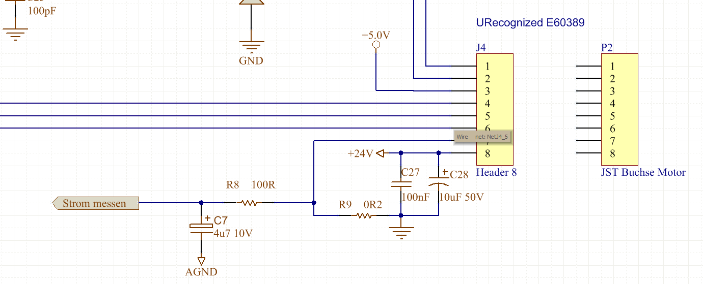
Ich verwende allerdings nicht das Discovery Board sondern eine eigene
Hardware, die einen 24V DC Motor ansteuert und dessen Stromaufnahme
gemessen werden soll. Bild im Anhang!
Probier mal das hier noch:
1 | ADC_ContinuousModeCmd(ADC1,ENABLE); |
2 | // und erst dann
|
3 | ADC_SoftwareStartConv(ADC1); |
nachdem du alles fertig initialisiert hast. Ansonsten sieht das richtig
aus. Normale Kanäle beziehen ihre Referenzspannung vom VREF+ Pin. So wie
ich das Referenzmanual verstehe, wird beim Temperatursensor die Referenz
aus dem VBAT Pin bezogen - gebe aber gerne zu, das ichs nicht wirklich
kapiere.

Achso, noch eines. Wenn dein Systemtakt bei 168Mhz liegt, ist ein
Prescaler von 4 grenzwertig, denn der ADC soll  mit < 32 Mhz laufen.
Vielen Dank für die Hilfe!

Der ADC geht aber direkt nach der 1. Messung auf Overrun, leider immer
noch.
Ich hatte den Prescaler jetzt mit 6 gewählt. Und dann noch mit 8
versucht.

Ich habe dann auf Einzelwandlung umgestellt und in einem Thread all 10ms
eine Wandlung durchgeführt. Dies hat wunderbar funktioniert. Ist aber
nicht das, was ich will.

Vielen Dank!
1 | // ADC1 regular channel8 configuration
|
2 | ADC_RegularChannelConfig(ADC1, ADC_Channel_8, 1, ADC_SampleTime_480Cycles); |
3 | // Enable ADC1
|
4 | ADC_Cmd(ADC1, ENABLE); |
5 | |
6 | ADC_ContinuousModeCmd(ADC1,ENABLE); |
7 | |
8 | // Start ADC1 Software Conversion
|
9 | ADC_SoftwareStartConv(ADC1); |
10 | while(ADC_GetSoftwareStartConvStatus(ADC1)); |
11 | }
|
ADC_SampleTime angepasst von 15 480 Cycles und das StartConvStatus Bit
abgewartet.

So läuft der ADC continuierlich!

Vielen Dank und Grüsse
MC Bu schrieb:
> ADC_SampleTime angepasst von 15 480 Cycles und das StartConvStatus Bit
> abgewartet.

Ah, super. Bei mir musste ich nicht aufs Statusbit warten, weil das dann
der Job des DMA Kanals ist. Für mehrere Kanäle wirds mit der DMA
einfacher als mit Polling.
hallo zusammen,
habe seit ein paar tagen ein stm32f4 und möchte photodioden messen
(quasi den strom sehr genau)
hierfür benötige ich auch einen ad wandler
ich bin allerdings neu auf dem gebiet der c programmierung kann mir
evtl. einer weiterhelfen mit einem "muster" für einen ad wandler?
damit ich mir das ganze mal anschaun kann und auf meine 4 pins auslegen
kann

wäre super danke
jojo schrieb:
> habe seit ein paar tagen ein stm32f4 und möchte photodioden messen
> (quasi den strom sehr genau)
> hierfür benötige ich auch einen ad wandler

Das ist allerdings so gut wie keine Info. Wieviele Werte brauchst du
denn in der Sekunde? Wie genau soll das sein?

Du bist dir hoffentlich im klaren darüber, das Photodioden eine gute
Verstärkung (z.B. mit einem Transimpedanz Verstärker) benötigen, um
überhaupt ein vom AD Wandler zu verwertendes Signal zu liefern. Das
erfordert einen sorgfältigen Aufbau, der von einem Anfänger nicht mal
eben so gemacht wird.
Es gibt kleine 16-bit Wandler mit I2C oder SPI Schnittstelle, die so
etwa 100.000 Abtastungen in der Sekunde hinkriegen, z.B. der AD7680,
aber das enthebt dich nicht der Notwendigkeit, einen guten Verstärker zu
bauen.

Die im STM32F4 verbauten AD Wandler sind jedenfalls dafür mehr schlecht
als recht, da die internen Störungen doch recht hoch sind.
Bitte melde dich an um einen Beitrag zu schreiben. Anmeldung ist kostenlos und dauert nur eine Minute.
Bestehender Account
Schon ein Account bei Google/GoogleMail? Keine Anmeldung erforderlich!
Mit Google-Account einloggen
Mit Google-Account einloggen
Noch kein Account? Hier anmelden.