Hallo

An all jene die gerne ein LCD mit einem KS0066U Controller ansteuern
möchten jedoch das Tutorial nicht geht, Ich hab die Lösung :D

Im anhang befindet sich eine LCD Routine für den KS0066U die Garantiert
Funktioniert!!!!

Viel spass

bei fragen, bitte direktes Mail an claudio.hediger@gmail.com
Kann mir jemand erklären wie die Variable "DelayCount1" deklariert
werden soll? DANKE
Hallo Leute,

kann es sein, dass das überhaupt nicht funktionieren kann!?
Da fehlen vorneweg mal die 30ms, die der KS060 sich nach dem Power up
gönnt!?

Hat den code jmd zum laufen gebracht?

Viele Grüße
Paul
Hallo,

könnte mir woll jemand den oben aufgeführten Assembler code in C
umschreiben? das Wäre echt super.
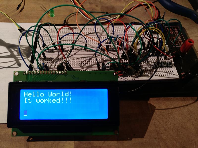
Hallo zusammen,

der Beitrag ist zwar schon älter aber aus dem Assembler-Tutorial hier im
Board wird noch immer auf ihn verwiesen, daher aktualisiere ich mal die
Informationen.

Hintergrund: Ich arbeite mich gerade durch das Tutorial und scheiterte
an der Inbetriebnahme eines Bona MC2004-01 4x20 Displays.

Es handelt sich um dieses Display (ich habe beide):
http://www.arduino-projekte.de/index.php?n=9

Mit dem Code aus dem Tutorial funktioniere das Ganze jedoch nicht und so
stieß ich auf diesen Thread.

Der Code von Adam Swann funktioniert tatsächlich. Es gelang mir damit
auf Anhieb, die Displays zu betreiben!

Der Themenersteller hat jedoch nicht den kompletten Code gepostet, das
sei hiermit nachgeholt:

Hauptprogramm:
1 | ; ****************************************************************** |
2 | ; L C D D I S P L A Y D E M O |
3 | ; ****************************************************************** |
4 | ; |
5 | ; Provides the entry point for a simple "Hello World" impelmentation |
6 | ; using my LCD routines. |
7 | ; |
8 | ; Author: Adam Swann |
9 | ; Homepage: http://www.velocity2.com/~adam/ |
10 | ; |
11 | ; http://www.adamswann.com/projects/avr-lcd/ |
12 | ; |
13 | ; See LCD.asm for more information. |
14 | ; |
15 | ; ****************************************************************** |
16 | |
17 | .nolist |
18 | .include "m8def.inc" |
19 | ; .include "m48def.inc" |
20 | .list |
21 | |
22 | .cseg |
23 | |
24 | |
25 | |
26 | .def Temp = r16 |
27 | .def Temp2 = r17 |
28 | |
29 | ; Define generic port names (change the 'A' to whatever you're using) |
30 | .equ LCD_PORT = PORTD |
31 | .equ LCD_DDR = DDRD |
32 | .equ LCD_PIN = PIND |
33 | |
34 | ; Define the pin numbers |
35 | .equ LCD_E = 1 |
36 | .equ LCD_RW = 2 |
37 | .equ LCD_RS = 3 |
38 | |
39 | .def DelayTime = r20 |
40 | .equ DelayCount1 = 128 |
41 | |
42 | |
43 | .org 0 |
44 | rjmp RESET |
45 | |
46 | RESET: ldi Temp, low(RAMEND) |
47 | out SPL, Temp |
48 | ldi Temp, high(RAMEND) |
49 | out SPH, temp ; Initialize Stackpointer |
50 | |
51 | ldi Temp, 0x00 |
52 | out LCD_PORT, Temp ; Clear the outputs |
53 | |
54 | ldi Temp, 0xFF |
55 | out LCD_DDR, Temp ; Set the direction to output |
56 | |
57 | ldi DelayTime, 255 ; Set the default delay length |
58 | ; (see my delay.asm) |
59 | |
60 | rcall LCD_Init |
61 | |
62 | rcall DELAY |
63 | |
64 | ldi r30, low(strInit1*2) |
65 | ldi r31, high(strInit1*2) |
66 | ldi Temp2, 20 |
67 | rcall LCD_PrintPM |
68 | |
69 | ; *** Send the cursor to beginning of second line |
70 | ldi Temp, 0b11000000 |
71 | rcall LCD_SendCmd |
72 | |
73 | ldi r30, low(strInit2*2) |
74 | ldi r31, high(strInit2*2) |
75 | ldi Temp2, 20 |
76 | rcall LCD_PrintPM |
77 | |
78 | |
79 | rcall DELAY |
80 | |
81 | |
82 | |
83 | FOREVER: rjmp FOREVER |
84 | |
85 | strInit1: .db "Hello World! " |
86 | strInit2: .db "It worked!!! " |
87 | |
88 | .include "lcd-routines.asm" |
LCD-Routinen:
1 | ; ****************************************************************** |
2 | ; L C D D I S P L A Y R O U T I N E S |
3 | ; ****************************************************************** |
4 | ; |
5 | ; Interfaces the AVR '8515 microcontroller with LCDs controlled |
6 | ; by the Samsung KS0066U (and similiar) LCD driver. |
7 | ; |
8 | ; Author: Adam Swann |
9 | ; Homepage: http://www.velocity2.com/~adam/ |
10 | ; |
11 | ; The code below is fairly straightforward and well-documented. |
12 | ; See my Web site or e-mail me if you need further instructions. |
13 | ; |
14 | ; I used an 8515 at 4 MHz. My LCD is Jameco Part #171715. |
15 | ; |
16 | ; Addendum: The Code is also tested on AtMega8 and AtMega48 |
17 | ; (by cosmicos at gmx.net) |
18 | ; |
19 | ; I wired the LCD display as follows (onto Port D) |
20 | ; AVR LCD |
21 | ; 0 --> no connection |
22 | ; 1 --> Enable on LCD |
23 | ; 2 --> R/W on LCD |
24 | ; 3 --> RS on LCD |
25 | ; 4 --> Data4 |
26 | ; 5 --> Data5 |
27 | ; 6 --> Data6 |
28 | ; 7 --> Data7 |
29 | ; |
30 | ; References: (URLs may be wrapped) |
31 | ; o KS0066U Datasheet |
32 | ; |
33 | ; ****************************************************************** |
34 | |
35 | ; *** LCD_Init: Routine to initialize the LCD. |
36 | LCD_Init: push Temp |
37 | |
38 | ldi DelayTime, 255 |
39 | |
40 | ; Put the LCD in 8-bit mode. Even though we want the display to |
41 | ; operate in 4-bit mode, the only way to guarantee that our commands |
42 | ; are aligned properly is to initialize in 8-bit. (The user might have |
43 | ; hit reset between nibbles of a dual 4-bit cycle.) |
44 | ldi Temp, 0b00110000 |
45 | out LCD_PORT, Temp |
46 | rcall LCD_PulseE |
47 | |
48 | rcall DELAY |
49 | rcall DELAY |
50 | |
51 | ; Now it's safe to go into 4-bit mode. |
52 | ldi Temp, 0b00100000 |
53 | out LCD_PORT, Temp |
54 | rcall LCD_PulseE |
55 | |
56 | rcall DELAY |
57 | rcall DELAY |
58 | |
59 | ; *** Send the 'FUNCTION SET' command |
60 | ; +------ Data: 0 = 4-bit; 1 = 8-bit |
61 | ; |+----- Lines: 0 = 1; 1 = 2 |
62 | ; ||+---- Font: 0 = 5x8; 1 = 5x11 |
63 | ldi Temp, 0b00101100 |
64 | rcall LCD_SendCmd |
65 | |
66 | ; *** Send the 'CURSOR/DISPLAY SHIFT' command |
67 | ; +----- S/C: 0 = cursor; 1 = display |
68 | ; |+---- R/L: 0 = left; 1 = right |
69 | ldi Temp, 0b00010100 |
70 | rcall LCD_SendCmd |
71 | |
72 | ; *** Send the 'DISPLAY ON/OFF' command |
73 | ; +---- Display: 0 = off; 1 = on |
74 | ; |+--- Cursor: 0 = off; 1 = on |
75 | ; ||+-- Blink: 0 = off; 1 = on |
76 | ldi Temp, 0b00001111 |
77 | rcall LCD_SendCmd |
78 | |
79 | ; *** Send the 'ENTRY MODE' command |
80 | ; +--- Direction: 0 = left; 1 = right |
81 | ; |+-- Shift Dislay: 0 = off; 1 = on |
82 | ldi Temp, 0b00000110 |
83 | rcall LCD_SendCmd |
84 | |
85 | rcall LCD_Clear |
86 | |
87 | pop Temp |
88 | ret |
89 | |
90 | ; *** LCD_PrintMem: Prints from memory. |
91 | ; Put the starting memory location in Z (r31:r30) |
92 | ; Put the number of characters to print in Temp2 |
93 | ; After execution, Z is at the character AFTER the last to be printed |
94 | ; and Temp2 is zero. |
95 | ; This function will not wrap if you the string is bigger than the LCD. |
96 | |
97 | LCD_PrintMem: push Temp |
98 | |
99 | LCD_MemRead: ld Temp, Z+ |
100 | rcall LCD_SendChar |
101 | dec Temp2 |
102 | brne LCD_MemRead |
103 | |
104 | pop Temp |
105 | ret |
106 | |
107 | ; *** LCD_PrintPM: Prints from program memory |
108 | LCD_PrintPM: push r0 |
109 | push Temp |
110 | |
111 | LCD_PMRead: lpm |
112 | mov Temp, r0 |
113 | rcall LCD_SendChar |
114 | adiw r30, 1 |
115 | dec Temp2 |
116 | brne LCD_PMRead |
117 | |
118 | pop Temp |
119 | pop r0 |
120 | ret |
121 | |
122 | |
123 | |
124 | ; *** LCD_Clear: Clears the display and sends the cursor home. |
125 | |
126 | LCD_Clear: push Temp |
127 | |
128 | ; *** Clear the display |
129 | ldi Temp, 0b00000001 |
130 | rcall LCD_SendCmd |
131 | |
132 | ; *** Send the cursor home |
133 | ldi Temp, 0b00000010 |
134 | rcall LCD_SendCmd |
135 | |
136 | pop Temp |
137 | ret |
138 | |
139 | ; *** LCD_SendCmd: Routine to write a command to the instruction register. |
140 | ; The value to be written should be stored in Temp. |
141 | ; The value is sent 4 bits at a time. |
142 | |
143 | LCD_SendCmd: push Temp |
144 | push Temp2 |
145 | |
146 | rcall LCD_WaitBusy |
147 | |
148 | mov Temp2, Temp ; Make a backup copy |
149 | andi Temp2, 0b11110000 ; Only use the upper nibble |
150 | out LCD_PORT, Temp2 ; Send it |
151 | rcall LCD_PulseE ; Pulse the enable |
152 | |
153 | swap Temp ; Swap upper/lower nibble |
154 | andi Temp, 0b11110000 ; Only use the upper nibble |
155 | out LCD_PORT, Temp ; Send it |
156 | rcall LCD_PulseE ; Pulse the enable |
157 | |
158 | pop Temp2 |
159 | pop Temp |
160 | ret |
161 | ; *** LCD_SendChar: Routine to write a character to the data register. |
162 | ; The value to be written should be stored in Temp. |
163 | ; The value is sent 4 bits at a time. |
164 | |
165 | LCD_SendChar: push Temp |
166 | push Temp2 |
167 | |
168 | mov Temp2, Temp ; Make a backup copy |
169 | rcall LCD_WaitBusy |
170 | mov Temp, Temp2 ; Make a backup copy |
171 | |
172 | andi Temp2, 0b11110000 ; Only use the upper nibble |
173 | ori Temp2, 0b00001000 |
174 | out LCD_PORT, Temp2 ; Send it |
175 | rcall LCD_PulseE ; Pulse the enable |
176 | |
177 | swap Temp ; Swap upper/lower nibble |
178 | andi Temp, 0b11110000 ; Only use the upper nibble |
179 | ori Temp, 0b00001000 |
180 | out LCD_PORT, Temp ; Send it |
181 | rcall LCD_PulseE ; Pulse the enable |
182 | |
183 | pop Temp2 |
184 | pop Temp |
185 | ret |
186 | |
187 | ; *** LCD_WaitBusy: Wait for the busy flag to go low. |
188 | ; Waits for the busy flag to go low. Since we're in 4-bit mode, |
189 | ; the register has to be read twice (for a total of 8 bits). The |
190 | ; second read is never used. |
191 | ; If you need more code space, this function could be replaced with |
192 | ; a simple delay. |
193 | |
194 | LCD_WaitBusy: push Temp |
195 | |
196 | ldi Temp, 0b00001111 ; Disable data bit outputs |
197 | out LCD_DDR, Temp |
198 | |
199 | ldi Temp, 0x00 ; Clear all outputs |
200 | out LCD_PORT, Temp |
201 | |
202 | LCDWaitLoop: ldi Temp, 0b00000100 ; Enable only read bit |
203 | out LCD_PORT, Temp |
204 | sbi LCD_PORT, LCD_E ; Raise the Enable signal. |
205 | nop |
206 | nop |
207 | in Temp, LCD_PIN ; Read the current values |
208 | cbi LCD_PORT, LCD_E ; Disable the enable signal. |
209 | rcall LCD_PulseE ; Pulse the enable (the second nibble is discarded) |
210 | sbrc Temp, 7 ; Check busy flag |
211 | rjmp LCDWaitLoop |
212 | |
213 | ldi Temp, 0b11111111 ; Enable all outputs |
214 | out LCD_DDR, Temp |
215 | |
216 | pop Temp |
217 | ret |
218 | |
219 | LCD_PulseE: sbi LCD_PORT, LCD_E |
220 | nop |
221 | nop |
222 | cbi LCD_PORT, LCD_E |
223 | ret |
224 | |
225 | ; *** Provide millisecond delay (DelayTicks specifies number of ms) |
226 | DELAY: push DelayTime |
227 | push r25 |
228 | |
229 | ldi r25, DelayCount1 |
230 | |
231 | DELAY1: dec r25 |
232 | brne DELAY1 |
233 | dec DelayTime |
234 | brne DELAY1 |
235 | |
236 | pop r25 |
237 | pop DelayTime |
238 | ret |
Der Code funktioniert nicht nur für 8515, sondern ebenfalls problemlos
mit dem AtMega8 bzw. AtMega48. Getestet bei 4Mhz und 8Mhz.

Ich habe den Code aus einem Thread bei AVRFreaks:
http://www.avrfreaks.net/forum/attiny2313-lcd-hd44780-source-code-asm-working

Der Code ist dort allerdings nicht unumstritten.

Für mich ist er dennoch eine große Erleichterung, da er auch mit meiner
Hardware funktioniert (im Gegensatz zum Code aus dem Tutorial). So macht
mir das weitere Lernen im Tutorial einfach mehr Spaß, da ich die
Resultate auch auf dem Display ausgeben kann und so ein besseres
Feedback habe :-)

Grüße
Ralf
Die Kritik bei AVRFreaks bezog sich übrigens auf eine nicht
datenblattkonforme Initialisierungssequenz. Die Initialisierung muss
insgesamt 3x durchlaufen werden. Dies ist im Tutorial-Code ebenso der
Fall.

Ich habe das nun analog zum Tutorial eingebaut und der Code läuft damit
besser. Zuvor zerhackte ein Reset die Displayausgabe, es musste immer
spannungsfrei gemacht werden und funktionierte erst beim erneuten
Einschalten wieder.

Mit der dreifachen Init-Sequenz klappt nun auch der Reset...
1 | ; Put the LCD in 8-bit mode. Even though we want the display to |
2 | ; operate in 4-bit mode, the only way to guarantee that our commands |
3 | ; are aligned properly is to initialize in 8-bit. (The user might have |
4 | ; hit reset between nibbles of a dual 4-bit cycle.) |
5 | ldi Temp, 0b00110000 |
6 | out LCD_PORT, Temp |
7 | rcall LCD_PulseE ; x1 |
8 | rcall DELAY |
9 | rcall LCD_PulseE ; x2 |
10 | rcall DELAY |
11 | ; Now it's safe to go into 4-bit mode. |
12 | ldi Temp, 0b00100000 |
13 | out LCD_PORT, Temp |
14 | rcall LCD_PulseE ; x3 |
15 | rcall DELAY |
Hi

>Mit der dreifachen Init-Sequenz klappt nun auch der Reset...

Da fehlt aber in deinem Programm etwas.

MfG Spess
spess53 schrieb:

> Da fehlt aber in deinem Programm etwas.

Wie gesagt: Ich bin noch Anfänger, arbeite gerade das Tutorial durch.
Mit solch nebulösen Andeutungen kann ich nichts anfangen.

Helfen würde hingegen wenn du konkret benennen könntest was ich anders
oder besser machen könnte.

Die Veränderung, die ich an Adam Swanns Code vorgenommen habe, habe ich
analog zur Kritik auf AVR-Freaks und analog zum Code des Tutorials
vorgenommen. In meinen Anwendungsfall mit Erfolg bzw. mit einer
spürbaren Verbesserung...

Ich lerne gerne weiter dazu :)

Danke vorab und Gruß
Ralf
HI

>Wie gesagt: Ich bin noch Anfänger, arbeite gerade das Tutorial durch.
>Mit solch nebulösen Andeutungen kann ich nichts anfangen.


Dann vergleiche doch mal dein Original (02.05.2017 11:29)
1 | ldi Temp, 0b00110000 |
2 | out LCD_PORT, Temp |
3 | rcall LCD_PulseE |
4 | |
5 | rcall DELAY |
6 | rcall DELAY |
mit deinem Auszug (02.05.2017 12:52)
1 | ldi Temp, 0b00110000 |
2 | out LCD_PORT, Temp |
3 | rcall LCD_PulseE ; x1 |
4 | rcall DELAY |
5 | rcall LCD_PulseE ; x2 |
6 | rcall DELAY |
Was ich in deinem Programm allerdings vermisse ist die Verzögerung nach
dem Einschalten des Displays.

Datenblatt vom KS0066:

Wait for more than 30 ms
after Vdd rises to 4.5 v

MfG Spess
spess53 schrieb:

>
> Dann vergleiche doch mal dein Original (02.05.2017 11:29)
>
> mit deinem Auszug (02.05.2017 12:52)

Du meinst die doppelten Delays?? Klappt bei mir sowohl als auch...
Ich schaue mir das aber noch einmal genauer an. Ich möchte die Delays
gerne unabhängig von der Taktfrequenz der MCU machen.

>
> Was ich in deinem Programm allerdings vermisse ist die Verzögerung nach
> dem Einschalten des Displays.

Wie gesagt: Es ist nicht "mein" Programm. Der Code stammt von Adam
Swann...

>
> Datenblatt vom KS0066:
>
> Wait for more than 30 ms
> after Vdd rises to 4.5 v
>

Stimmt! Ich versuche mal, das einzubauen.
Gute Übung... :-)

Danke für die konkreten Hinweise!
Gruß
Ralf
Hi

>Du meinst die doppelten Delays?? Klappt bei mir sowohl als auch...

Unter welchen Umständen getestet? Also auch z.B. Start aus dem
stromlosen Zustand.

MfG Spess
Angehängte Dateien:
-

29081159wv.jpg
48 KB
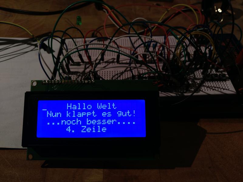
So, ich habe nun analog zum Tutorial-Code die Delays an die Taktfrequenz
gekoppelt und außerdem ein 30ms Delay zu Beginn eingebaut...

Es gibt wieder eine spürbare Verbesserung in der Funktion. Bislang
führte ein Reset zu einer deutlich wahrnehmbaren Veränderung des
Displays (Störungen etc.) bevor sich der Inhalt wieder aufbaute.

Nun gibt es keine Störungen mehr. Ein Reset bewirkt einen sauberen
Neuaufbau des Displayinhaltes!

Des Weiteren habe ich die Ansteuerung der 4 Displayzeilen etwas
vereinfacht.

Hier der Code...
Bitte melde dich an um einen Beitrag zu schreiben. Anmeldung ist kostenlos und dauert nur eine Minute.
Bestehender Account
Schon ein Account bei Google/GoogleMail? Keine Anmeldung erforderlich!
Mit Google-Account einloggen
Mit Google-Account einloggen
Noch kein Account? Hier anmelden.