-
PDF
T-3.pdf
3000B-4888 1 53 SCREW FOR FOOT 602-MD26-108 8 54 RATING LABEL 501-DJ3000D-1459 1 55 AC POWER CORD( L=1900+-50mm,VDE TYPE ) 409-DJ2-070A 1 56 SUB-START PCB ASS'Y 704-5000-4845 1 57 DC PCB ASS'Y 704-5000-4848 1 58 SCREW ( BTP,DIA3*8 ) 602-DJ3000-277 2 59 WASHER 604-ST100-195 8 60 WASHER(t=1mm) 606-ST100
in „Eprom von Denon DJ Laufwerk defekt Winbond 78e52“ · Mikrocontroller und Digitale Elektronik ·
-
PDF
rpb_electronic_taschenbuecher_gesamtverzeichnis_1979_1980.pdf
electron1979 taschenbücher Gesamtverzeichnis electronic-taschenbücher in numerischer Reihenfolge E l 4 19 Der Hobby-Elektronikerlerntmessen. Mitrich Optoelektronik. Von den Eigenschaften der op tigen Maßmethoden dem Fehler auf die Schliche toelektrischen Bauelemente bis zu ihrer vielseiti kommen. Von lng. DieterNührmann.-2. Auflage. genschaltungstechnischenAnwendung.Von lng. Doppelband. DM 7.80. L Ratheiser und Dipl.-lng. Dr. H. Pichler. - Drei ISBN 3-7723-0042-1 fachband. DM 9.80. ISBN 3-7723-0191-6 5 Brand- und Elnbruchmeldeanlagen. Notwen 20 Schadensverhinderung. Von Konrad Bartels. -ür Methodische
in „Welche Bücher sind im "Radio-Praktiker Bücherei E-Book-Bundle 3 - Ton, Musik & Aufnahme"?“ · Offtopic ·
-
PDF
iHSV60en.pdf
is protected by copyright - Dieses Dokument ist urheberrechtlich geschüt25.01.2024 iHSV(C)60 Integrated AC Servo Motors 6. Motor Specifications: iHSV60-30- iHSV60-30- Name: 40-48-XX 20-36-XX Unit Rated Power 400 200 W Rated Current (RMS) 11.2 8.5 A Rated Torque 1.27 0.65 N·m-1 Rated Speed 3000
in „Kabel zum Anschluß eines Servomotors“ · Analoge Elektronik und Schaltungstechnik ·
-
PDF
Funktechnik-1985-12_Datasheet_TBB146.pdf
Technics. Der BGH hat alsletzten zung der rft-Leistungsgemeinschaft) 504 Funk-Technik 40 (1985),Heft 12 l i i l l i l l l l Mitteilungen aus dem ZVEH 2. Betriebswirtschaft Die „ARF“ sind nichtnur für denBetriebs überschreitet.Einnicht eingetragener Ne (Struktur der Werkstattkosten, Ver inhaber gedacht
in „Controller PLL TBB146“ · Markt ·
-
PDF
TJA1020.pdf
note 4 r(slope)(norm)(rec)ormal slope rise time normal slope mode; − 12 22.5 s LIN (0% to 100%) C L 6.8 nF;R L 660 ; V = 12 V; transition BAT from dominant to recessive; note 5 tslope(norm) normal slope symmetry normal slope mode; −4 0 +4 s C L 6.8 nF;R L 660 ; V BAT= 12 V; t − t f(slope)(domr(slope
in „[S] MCP2004 LIN Tranceiver oder andere gesucht“ · Markt ·
-
PDF
info-uiir2156.pdf
(S)&(PbF) 120 250 125 C o 100 125 C 200 o 75 C 75 C ) 80 c o e o e 150 25 C S 25 C n ) () H 60 ( -25 C L o I100 F -25 C tR t 40 50 20 0 0 11 12 13 14 15 11 12 13 14 15 V (V) VCC (V) CC Graph 25. FALL(HO) vs CC vs Temperature (IR2156) Graph 26. RISE(LO)vs VCC vs Temperature (IR2156) 120 125 C 100 o 75 C 80 c S 25 C ( O 60 L o A -25 C t 40 20 0 11 12 13 14 15 V (V) CC Graph 27. FALL(LO)vs VCC vs Temperature (IR2156) www.irf.com 15 ( S&(PbF) IR2156 Functional Description VC1 CVCC Under-voltageLock-OutMode(UVLO) DISCHARGE
in „Leuchtstoffröhren Vorschaltgerät 24V Reparatur-Tipp gesucht“ · Fahrzeugelektronik ·
-
PDF
Intersil_ICL8052_ICL8068_ICL71C03.pdf
3081.2 O M M EN D E NO R EC 1 Precision 4 / Digi2, A/D Converter Features itle The ICL8052A or ICL8068A/lCL71C03 chip pairs with their • Typically Less Than 2µV P-P Noise (200.00mV Full Scale, L80 multiplexed BCD output and digit drivers are ideally suited lCL8068A AA/ for the visual display DVM/DPM market
-
PDF
L9110-Motor-Driver-Datasheet.pdf
: Sales@asic.net.cn Motor control driver chip L9110 Electrical characteristics: Logical relationship: SymbolParameters Range Units Min TypicalMax IA IB OA OB VCC Supply Voltage 2.5 6 12 V Quiescent Current H L H L Idd - 0 2 uA L H L H Iin Operating current200 350 500 uA L L L L IC Continuous 750 800 850 mA Current peak H H L L IMax - 1500 2000 mA Pin waveform diagram: input A input B output A output B Application Cir:uit VCC + Forward L9110 signal DC motor M backward
in „Motorcontroller (H-Brücke) gesucht, der schon mit einer LiPo Zelle funktioniert?“ · Analoge Elektronik und Schaltungstechnik ·
-
Bild
Screenshot eines Logikanalysators
Threshold 1.40v Pre-Trigger Buffer 1% Measurement A Source CLK1 Signal Wire Pattern Edge Cursor A CLK D3 L 0 -160us -140us -120us -100us -80us -60us -40us -20us T+139us +20us +40us +60us +80us +100us +120us +140us +160us MOSI D1 H 1 MISO D2 H 1 CS D0 L J 0
in „[?] libmpsse.dll, Fehler bei SPI-Lesen“ · Softwareentwicklung · · Oszi-Bilder
-
PDF
QN8027.pdf
pitch 0.50 (BSC) E Package’s outside, Y-axis 2.900 3.00 3.100 E1 Lead to lead, Y-axis 4.750 4.90 5.050 L Foot length 0.400 0.60 0.800 θ Foot to board angle 0° - 6° Notes: 1. Pin 1 visual index feature may vary, but must be located within the area indicated in the drawing. 2. Dimensioning and tolerance per
in „FM Transmitter - Antenne verstehen und messen“ · HF, Funk und Felder ·
-
Bild
Schaltplan einer automatischen Drehzahlumschaltung
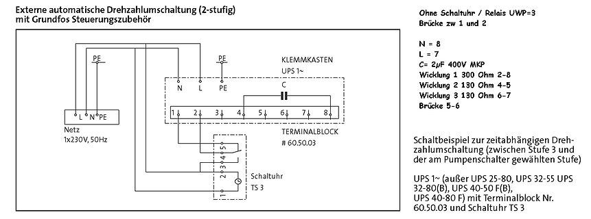
Drehzahlumschaltung (2-stufig) mit Grundfos Steuerungszubehör Ohne Schaltuhr / Relais UWP=3 Brücke zw 1 und 2 N = 8 L = 7 C= 2µF 400V MKP Wicklung 1 300 Ohm 2-8 Wicklung 2 130 Ohm 4-5 Wicklung 3 130 Ohm 6-7 Brücke 5-6 KLEMMKASTEN UPS 1~ TERMINALBLOCK # 60.50.03 Netz 1x230V, 50Hz PE N L Schaltuhr TS 3 Schaltbeispiel
in „Anschlussplan Umwälzpumpe Grundfos UMC32-30“ · Haus & Smart Home · · Schaltpläne
-
Bild
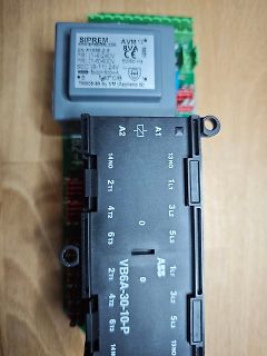
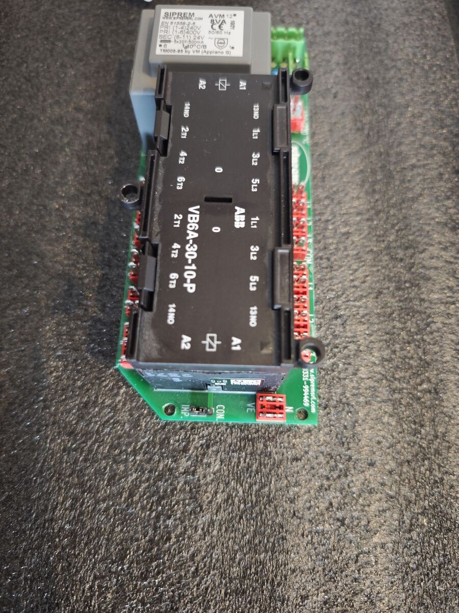
ABB VB6A-30-10-P Leistungsschalter auf Leiterplatte
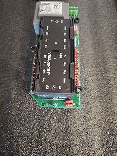
SIPREM AVM12 50/60 Hz ABB VB6A-30-10-P 1NO 1NC 3L1 3L2 3L3 2T1 2T2 2T3 1L1 1L2 1L3 4T1 4T2 4T3 13NO 14NO A1 A2
in „Brauche Input, bin ratlos“ · Mechanik, Gehäuse, Werkzeug · · Platinenfotos
-
Thread
Funktechnisches, neuer OrangePi, SigVSA und mehr
leichter – als Hauptprozessor kommt wieder ein Cix P1 zum Einsatz. ### Nordic Semiconductor nRF54L15 Tag – AirTag-artiges Entwicklungsboard für nRF54L15 Nordic Semiconductor möchte den nRF54 im Bereich Matter-Smarthomes platzieren. Mit dem Tag steht ein vom Format her an den Apple AirTag erinnerndes
/2.png) Bildquelle: https://www.nordicsemi.com/Nordic-news/2026/06/Nordic-launches-compact-nRF54L15-prototyping-tag-optimized-for-Apple-Find-My-and-Google-Find-Hub Textuell beschreibt man das neue Produkt folgendermaßen: [c] . It supports development for Apple Find My and Google Find Hub networks
Mikrocontroller und Digitale Elektronik ·Tam H. · ·1 Antworten
-
PDF
Lichttechnik_Richtwerte_und_Anwendungen_Teil_1_Spektralkurven.pdf
6) 612 2) St 3 7 10 83 3 0,4 0 621 2) St 3 5 15 80 2 2 0,8 0 65370 VE 1621 625 1) St 3 62 6 32 59 60 67 74 62 0,85 0,77 <1 55480 6) 1) St 4 62 6 32 59 60 67 74 62 0,85 0,77 0 1) St 5 62 6 32 59 60 67 74 62 0,85 0,77 0 1) St 6 62 6 32 59 60 67 74 62 0,85 0,77 0 627 1) St 3 3 4 93 2 2 45 57 0,66 0,52
in „Filterscheibe für rote LED-Displays“ · Mechanik, Gehäuse, Werkzeug ·
-
Bild
Technische Zeichnung und Daten einer Antennenwicklung
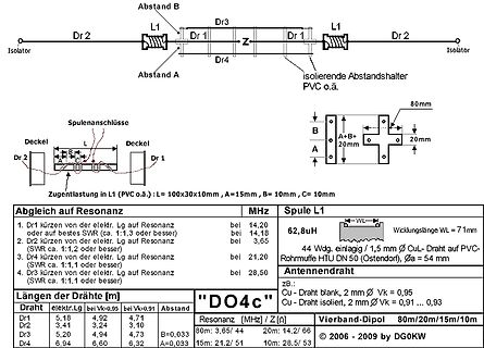
Abstand B, Dr3, L1, Dr 2, Isolator, Dr 1, Z, Dr 1, Dr 2, Isolator, Abstand A, PVC o.ä., Spulenanschlüsse, Deckel, L, Deckel, Dr 2, Dr 1, Zuglast in L1 (PVC o.ä.) : L = 100x30x10mm , C = 10mm, Abgleich auf Resonanz, MHz
in „KW-Multiband-Dipolantennen DOxy simulieren“ · HF, Funk und Felder · · Diagramme
-
PDF
grundig32zollLedTV.pdf
50 D907 T 60 106 L807 T 75 43 R213 B 83 65 R629 T 49 32 C318 T 100 61 C706 T 168 15 C843 T 62 69 C1004 T 91 49 D908 T 59 106 L900 T 73 105 R214 B 95 73 R700 T 172 13 C319 B 125 46 C707 T 168 16 C844 T 44 69 C1005
in „Reparaturbericht LED-TV Grundig 32 VLE 5620 BN Ton gut, aber kein Bild“ · Analoge Elektronik und Schaltungstechnik ·
-
PDF
MC1377.PDF
R29 R33 R34 F R46 500 T55 R56 T56 F T40 1.0k T41 1.0k A R48 R64 P / R39 R47 500 R57 500 F 500 1.0k l 1.0k A T39 R40 R41 t R50 R61 R62 R65 P 2.0k 2.0K u 220 2.0k 2.0k 220 Y B R – T43 T44 B l t T60 T61 B–YClamp r 11 B T62 T63 T64 T65 T45 T46 R60 R47 4.7k 4.7k T47 T59 T58 T48 T66 R38 R43 R44 R45 R49 R52
in „Problem beim FBAS Signal am Amiga 500“ · Analoge Elektronik und Schaltungstechnik ·
-
PDF
4012002220-__IC_MT3608_SMD_SOT23-6L_AEROSEMI_.pdf
Current(mA) Load Current(mA) Line/Load Regulation Line/Load Regulation VOUT=5V VOUT=18V 5.5 19 V V e e l l V 5 V18 u u u u O VIN=3V O VIN=5V VIN=3.7V VIN=12V VIN=4.2V VIN=16V 4.5 17 0 200 400 600 800 1000 0 100 200 300 400 500 Load Current(mA) Load Current(mA) Operation Frequency vs. Input Voltage Operation
in „SMD Bauteilidentifizierung (B6282)“ · Analoge Elektronik und Schaltungstechnik ·
-
Bild
Siprem AVM 12VA Transformator und VB6A-30-10-P Schütz
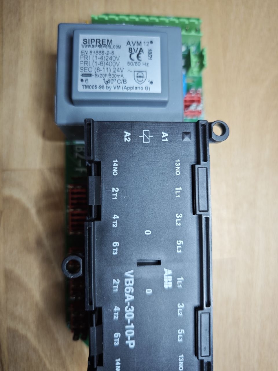
SIPREM AVM 12VA WWW.SIPREM.COM EN 61558-2-6 PRI (1-6) 400V SEC (8-11) 24V 50/60 Hz 8x20p A/mA TM006-95 by VM (Appiano G) A2 A1 14NO 13NO 2T1 1L1 4T2 3L2 6T3 5L3 0 0 VB6A-30-10-P 1L1 0 3L2 5L3 13NO 14NO A2 A1
in „Brauche Input, bin ratlos“ · Mechanik, Gehäuse, Werkzeug · · Fotos
-
Bild
Siprem Transformator und ABB Relais auf Leiterplatte
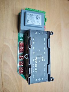
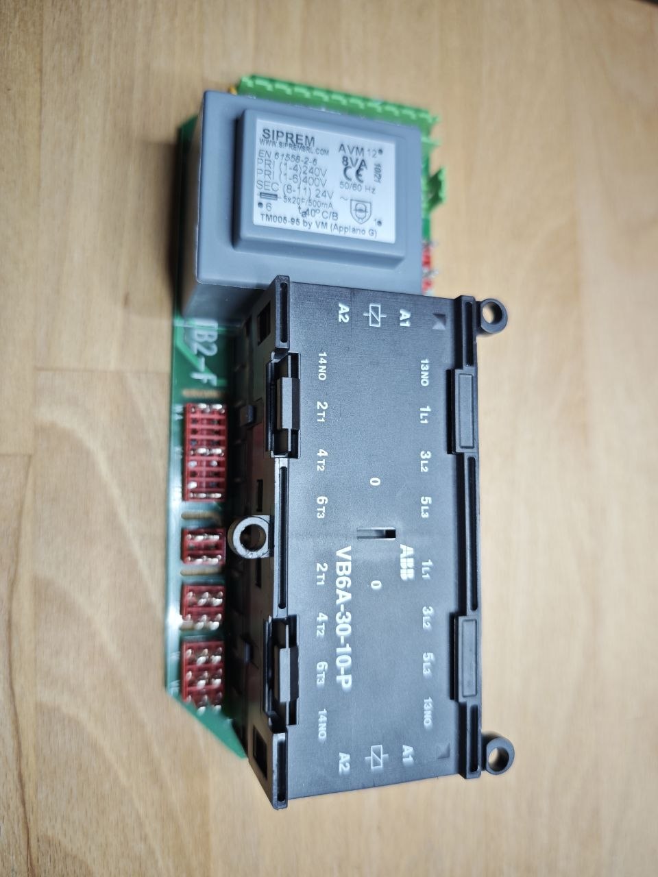
SIPREM AVM 12 8VA 10/2 CE EN 61558-2-6 PRI (1-4) 240V PRI (1-6) 400V 50/60 Hz SEC (8-11) 24V 5x20F/500mA 40°C/B TM005-95 by VM (Appiano G) A2 A1 14NO 13NO 2Tr 1L1 4T2 3L2 6T3 5L3 VB6A-30-10-P 2Tr 1L1 4T2 3L2 6T3 5L3 14NO 13NO
in „Brauche Input, bin ratlos“ · Mechanik, Gehäuse, Werkzeug · · Fotos
-
PDF
Elektronusches_Uhren_Relay-V4.pdf
- - - 0a ',rII! O,J'3)1F 13 19 RII,ZI R21 ~ZI ZIfR22 ~R16 I 20 J,9k lOk I -l I.Ok 11J]9k 61 i~Zf13 +C6 6 DW ~ DW 6 9 1 10 B Up T 0971 ~ L ._t-.-1 i D W 6 9 ~ DW691 " B B RI7 ZI G8~t7 G2 L~Zf5.6 B60[800 ~G4 ~I7GI5 IIlt'9 "IR26 4,7k 7 ~2N 14 3055 13 7Zf5,6J 11l,.7k 9,70k ~ ~ 11 W ~ B /~lL 1I R3 11 700 11 FZHZ!,I rc s ~~~ 71FZH21,1 IOD I, 6 I. ~Qf ulf 18 8 69l.~ 614l~ t R25 11.l5)1F c 47072 .D _ ~lf TlJ 9 ~ ~ 4 ZIRI3 7 ~ Tll I R5 _V I 8 -./:'".l R6 F ~ 67 ~[4: +1)1F 330,1.2k ,"-' 3JO.lZh
in „Polwechselnden Impuls mit Transistoren verstärken“ · Analoge Elektronik und Schaltungstechnik ·
-
Bild
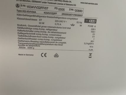
Typenschild eines Kühlschranks
Gesamt/total gross volume/volume brut total 90 W 0,70 A Kühlfach/fridge comp./comp. refrigerateur 285 l Kellerfach/cellar comp./comp. de rafraichissement 19 l Kaltlagerfach/chill comp./comp. conservateur 0 l Tiefkühlfach/frozen-food comp./comp. congelateur 0 l Gefrierfach/freezer comp./comp. congelateur 1 l Gefrierverm./freezing capacity/pouvoir de congelat. 6 l Temperaturanstiegszeit/temperature rise time/montée en température 3,0 kg/24 h R60a 069 g CE D"E"
in „Siemens Kühl-Gefrierkomi vereist im Kühlteil“ · Haus & Smart Home · · Fotos
-
PDF
Bauteile.pdf
n g n u l i 2 3 4 r r b h z r r r u m t z N Ty B W W W B B D A 1 Mos-Fet P12MN50 500V 12A 0,3Ω TPO220 2 Mos-Fet 5R140P 550V 23,0A 0,140Ω TPO220 3 Feinsicherung 250V 4,0A Flink PE10St. 40 4 Feinsicherung 250V 0,315A
in „Elektronik Bauteile Neuwertig , meist Leistungselektronik“ · Markt ·
-
PDF
Spec_Sheet_F12_PWM_EN.pdf
LMIED BLACK W Y ARRAN T Fan Specifications Shipping Information Single Fan – Black Dimensions 120 (L) x 120 (W) x 25 (H) mm Box Dimensions 123 (L) x 123 (W) x 27 (H) mm Weight 105 g Gross Weight 143 g Speed 230–1350 rpm, 0 rpm <5% PWM SKU ACFAN00203A rpm Control Pulsweitenmodulation – PWM EAN 4895213702959
in „2pol-/3pol-Lüfter mit PWM-Betriebsspannung“ · Analoge Elektronik und Schaltungstechnik ·
-
PDF
Battery-Protection-LiIon-2S-HY2120.pdf
SIP CONTROL OUTPUT VOLTAGE(OD&OC) OD Pin Output “H” Voltage V DH VDD-0.1 VDD-0.02 V OD Pin Output “L” Voltage V DL 0.2 0.5 V OC Pin Output “H” Voltage V CH VDD-0.1 VDD-0.02 V OC Pin Output “L” Voltage V 0.2 0.5 V CL 0V BATTERY CHARGE FUNCTION Charger start Available 0V voltage(available 0V battery V0CH
in „[S] LiIo-Akku“ · Markt ·
-
Bild
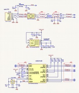
Schaltplan eines USB-Hubs mit CY7C65642-28LTXC
BU60 VBUS C61 100nF GND D-Up1_P TR65 I/O 1 D-Up2_P L65 D-Up3_P R67 D-Upload_P D-Up1_N VCC GND D-Up2_N R66 27R D-Upload_N GND S1 D- 2 D-Up2_N 1 D-Up3_N 2 D- 3 GND S2 Shield Shield USB 2.0 Type B GND+ GND C66 47pF C67 47pF C50 100nF C51 100nF VCC+3,3V IC50B +5V_IN +3,3V_D L50 60 Ohm -3,3V_D -3,3V_A -3,3V_A GND-PAD C53 100nF C54 100nF C55 100nF CY7C65642-28LTXC VCC+3,3V USB-HUB R56 10K R57 10K R58 10K R59 10K D-Upload_N D-Kamera_N DM-1 DP+1 D-Kamera_P DM-1 DP-1 D-Upload_P
in „USB-Hub funktioniert nicht.“ · Mikrocontroller und Digitale Elektronik · · Schaltpläne
-
Bild
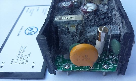
Defektes Netzteil mit verschmutzter Platine
SNT19-24/9 L1 L2: 220-400 VAC L N: 220-240 VAC 50/60 Hz 0,21-0,14 A L1 L2 UU10.5-15 TVR 14821 RACOPOWER S01 280126
in „Elekotromaten TS971“ · Analoge Elektronik und Schaltungstechnik · · Platinenfotos
-
PDF
53131a_53132a_bedienungsanleitung_deutsch_komprimiert.pdf
oder OFF (AUS) oder r bis zur Betätigung einer beliebigen Taste i ee Schlleifdurchlaufenn sol en.. 2-60 BBedieun g de UUnivers l ählers DDa UUtility-enü (Die tprogram e) Ferne kann s pezifiziertwerden, oo ddieFehle rmeldungenn aan eine Dr ucker, die RS-23 oder den HP-P ges et werd solle - bei Nur IB endet
in „[V] HP/Agilent 53131a/53132a Bedienungsanleitung deutsch“ · Markt ·
-
Artikel
Platinenhersteller
-08-18 AISLER¹) 2 160 100 1.6 1 33.21 2026-08-18 AISLER¹) 4 20 20 1.6 9 6.18 2026-08-18 AISLER¹) 4 60 50 1.6 9 10.20 2026-08-18 AISLER¹) 4 160 100 1.6 9 30.36 2026-08-18 AISLER¹) 4 60 50 0.8 9 11.14 2026-08-18 AISLER¹) 4 60 50 0.8 5 33.46 2026-08-18 Ätzwerk 1 160 100 1.6 7 59.50 2016-07-05 Ätzwerk 2
Gewerbetreibende 1-48 Lagen Leiterplatten und SMD-Schablonen, ab 1AT Express, seit 30 Jahren Standard 2L: 4AT Produktionszeit, 4L: 5AT Produktionszeit, 6L & 8L: 6AT Produktionszeit Standard: 0.1mm Leiter, 0.2mm Bohren Preiswerte Spar-Option ab 8AT Inklusive: Kompletter Design-Rule-Check, Tooling, Lötstopp
Artikel ·
-
PDF
OA5671_de.pdf
Daten Relaistyp OA 5671, OA 5672 OA 5681, OA 5682 1.0 Spule 1.1 Nennspannung DC 6; 12; 15; 20; 24; 48; 60; 110 V (andere auf Anfrage) 1.2 Nennverbrauch 0,53 W 1.11 Spannungsbereich 0,7 ... 2,2 N 1.13 Halteleistung (bei 0,5 x U N 0,14 W 2.0 Kontakte 1) 2.1 Kontaktbestückung 1 Wechsler 2.2 Kontaktwerkstoff
in „Ersatztyp für altes Finder Relais gesucht“ · Analoge Elektronik und Schaltungstechnik ·
-
PDF
RasperryPI_CAN-S.pdf
33 34 34 33 IN_A 37 38 IN_E 38 37 IN_B 39 40 IN_D 40 39 IN_C X1 X2 GND GND GND GND +5V 1 7 R C C R4 60R R8 +3V3 60R C5 k 9 1 R 3k3 2k2 4n7 k N R 1 G R5 R6 IC1 D 100k IC2 GND GND Q1 2 RXCAN TXCAN 3 N 5 RS CANH 6 CANH 2 10MHz 8 CLKOUT/SOF 4 G R3 VREF CANL CANL 3 OSC1 TX0RTS 5 1 4 +5V 7 TX1RTS 6 TXD RXD A A X3 D OSC2 TX2RTS 11 3 B B GND D C1 C2 V RX0BF 10 VDD L L 3 17 RESET RX1INT 12 VSS 2 C3 V V 33p 33p + 16 CS 5 5 14 SI SO 15 MCP2551 100n S S 13 SCK D P D P VDD 18 +3V3 GND VSS 9 GND C4 100n GND MCP2515 GND E E 1 2 3 4 5 6 7 8
in „MCP2515 CAN-Bus Modul“ · Mikrocontroller und Digitale Elektronik ·
-
Bild
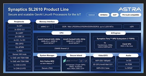
Blockschaltbild Synaptics SL2610 Produktlinie
99x GPIO 12x sPWM 1x ADC Sensor HW mute Memory Interface eMMC 5.1 DDR: 16bit LPDDR4x/LPDDR4/DDR4/DDR3L up to 3,200 MT/s xSPI CPU Arm® Cortex® A55, 2GHz 32KB-I/D L1, 64KB L2 Arm® NEON™ 256KB Shared L3 AI Engines Synaptics Torq™ NPU Subsystem (1 TOPS) T1 Transformers, CNNs Int8/Int16/BFloat16 Coral NPU
in „Neuer OrangePi, neue Mikrocontroller und dazugehörende Software“ · Mikrocontroller und Digitale Elektronik · · Diagramme
-
Bild
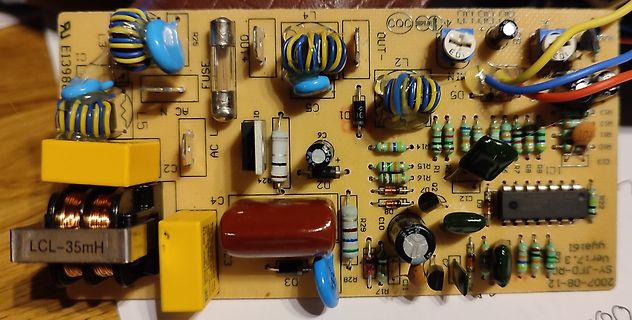
Bestückte Leiterplatte eines Netzteils
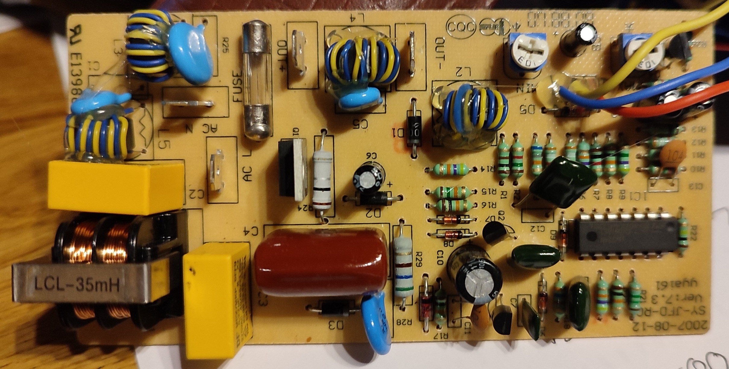
RJ E1396 L4 L1 L2 OUT C00 L3 L4 L5 AC N L6 C4 C5 C6 D1 D2 D3 D5 R1 R2 R3 R4 R5 R6 R7 R8 R9 R10 R11 R12 R13 R14 R15 R16 R17 R18 R19 R20 R21 R22 R23 R24 R25 R26 R27 R28 R29 R30 R31 R32 R33 R34 R35 R36 R37 R38 R39 R40 R41 R42 R43 R44 R45 R46 R47 R48 R49 R50 R51 R52 R53 R54 R55 R56 R57 R58 R59 R60 R61 R62 R63 R64 R65 R66 R67 R68 R69 R70 R71 R72 R73 R74 R75 R76 R77 R78 R79 R80 R81 R82 R83 R84 R85 R86 R87 R88 R89 R90 R91 R92 R93 R94 R95 R96 R97 R98 R99 R100 R101 R102 R103 R104 R105 R106 R107 R108
in „Hilfe bei Platinenaufbau (Transistorerkennung) der Dekopiersäge KFZ-400RV (SY-JFD-RC)“ · Analoge Elektronik und Schaltungstechnik · · Platinenfotos
-
Datei
fritzbox_7590_log.txt
mpoa:atm_mpoa_init: mpc.c: initialized [ 6.372054][ T1] KOAM is loaded successfully. [ 6.376699][ T1] l2tp_core: L2TP core driver, V2.0 [ 6.381644][ T1] l2tp_ip: L2TP IP encapsulation support (L2TPv3) [ 6.388198][ T1] l2tp_netlink: L2TP netlink interface [ 6.393315][ T1] l2tp_eth: L2TP ethernet pseudowire support (L2TPv3) [ 6.399796][ T1] l2tp_ip6: L2TP IP encapsulation support for IPv6 (L2TPv3) [ 6.407174][ T1] 8021q: 802.1Q VLAN Support v1.8 [ 6.413876][ T1] audit: type=1400 audit(5.736:2): apparmor="STATUS" info
in „FritzBox 7590 Boot Loop“ · Mikrocontroller und Digitale Elektronik ·
-
PDF
Magic_switch.pdf
Schalttechnik Schalttechnik Montagezeichnung e h u L r e i L l oi P e L MultiSwitch MagicSwitch Technische Details e n h Produktvorteile Anwendung C } Unsichtbare Schalter für vielfältige Anwend} Schalten von Vorschaltgeräten und } Anschluss von 1 - 4
in „Hilfe bei Elektrotechnik im Schreiner-Meisterstück“ · Analoge Elektronik und Schaltungstechnik ·
-
PDF
M48Z02.pdf
25 50 60 ns AVWH Address valid to WRITE enable high 60 120 140 ns tAVEH Address valid to chip enable high 60 120 140 ns WHQX WRITE enable high to output transition 5 10 10 ns 1. noted).or ambient operating tempArature
in „[S] DALLAS DS1220Y-150 NVRAM (NOS)“ · Analoge Elektronik und Schaltungstechnik ·
-
PDF
HD66766R.PDF
DB3 DB2 DB1 DB0 R L7 L6 L5 L4 L3 L2 L1 L0 0 C6 C5 C4 C3 C2 C1 C0 0 Figure 5 Status Read Instruction Start Oscillation (R00h) The start oscillation instruction restarts the oscillator from the halt state in the stanAfterode
in „LCD-Modul F51661GNCJU-MLW-AA * Info *“ · Mikrocontroller und Digitale Elektronik ·
-
Bild
Aufschrift einer Flutinstahl-Spule
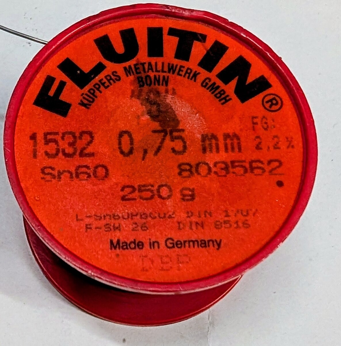
FLUTIN KÜPPERS METALLWERK GMBH BONN FG: 1532 0,75 mm 2,2% Sn60 803562 250 g L-Sn60UP60C02 DIN 170/ F-Sn6 26 DIN 8516 Made in Germany
in „[S] Suche Lot 'Felder ISO-Core "RA" '“ · Markt · · Fotos
-
PDF
trafo_datasheet.pdf
R5 MAX. N P P7 T 1 S .188 ± .015 DIA. (2 HOLES) STYLE A 1 3 MD MW W MAX. PRIMARY SECONDARY 117V, 50/60 Hz 4 24V CT MS (4 PLACES) STYLE NV 2 5 SCHEMATIC DIAGRAM STANCOR Sec. VA Pri. Lead Wires Sec. Lead Wires Mtg. Wt. U.L. Color Color Dimensions - Inches Part No. Curr. Cap. #1 #2 Awg #3 #4 (C.T.) #5 Awg
in „[V] Trafo, Gleichrichter, Elko für 115V/24V 12A Netzgerät“ · Markt ·
-
PDF
SHUTTLE_SPCEL02_DB-DE.pdf
Speichermodul (260-pin) DDR4-3200, max. 32 GB Shuttle Edge PC Barebone SPCEL02 M.2-2242 M.2-SSD-Karte (SATA) L: 42 mm unterstützt eine M.2-2242 SSD-Karte mit SATA-Schnittstelle (nicht PCIe/NVMe) M.2-2280 L: 80 mm Bemerkung:Eine längere M.2-2280-Karte wird auch unterstützt, falls kein WLAN-Modul installiert wird
in „[V] Shuttle SPCEL02“ · Markt ·
-
PDF
Bauteile.pdf
0,045Ω SO8 Treiber1x N/1x PKanal 35 Bauteil Mos-Fet W5NB90 900V 9,7S 1Ω 282 36 Bauteil Mos-Fet STW13NB60 600V 13A 0,54mΩ NKanal 112 37 Bauteil Mos-Fet IRL 2910PBF 20V 61A 132mΩ TO-220AB NKanalMosFET 186 38 Bauteil Mos-Fet BUZ20 100V 12A 49 39 Bauteil Mos-Fet IXKR40N60C 600V 38A NKanalMosFET 11 40 Bauteil Mos-Fet IRFP054 60V 70A TO-247 Powermosfet 78 41 Bauteil Mos-Fet IRF P360 400 23A NKanal 25 42 Bauteil Mos-Fet 13NK60Z 600V 13A NKanal 14 43 Bauteil Mos-Fet IRFPG50 1000V 6,1A N Kanal 18 44 Bauteil Mos-Fet STW12NK90Z 900V
-
Bild
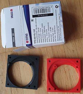
Verpackung und 3D-gedruckte Lüfterhalterungen
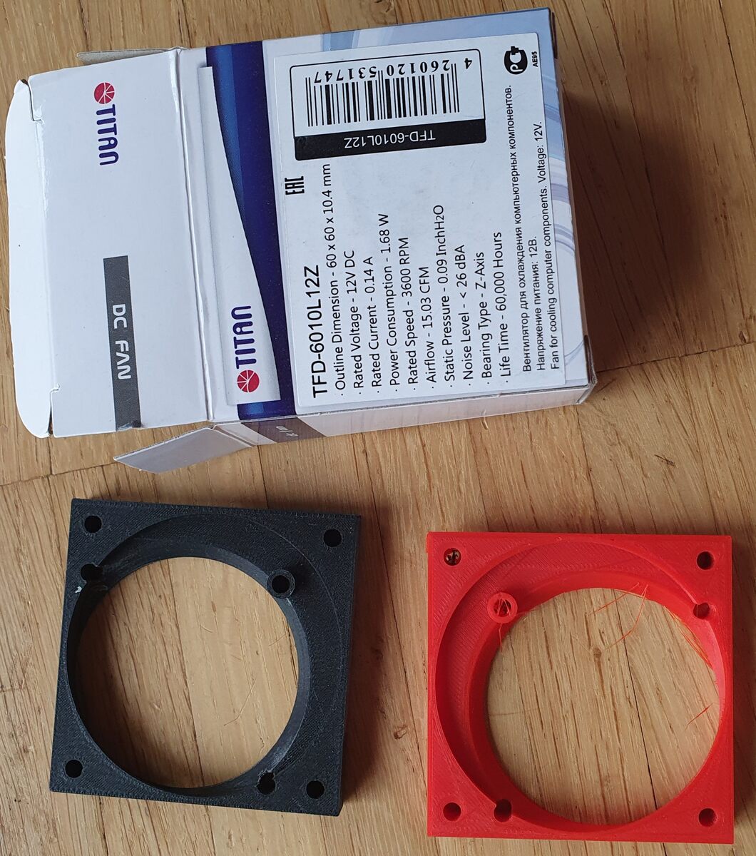
TITAN TFD-6010L12Z Outline Dimension - 60 x 60 x 10.4 mm Rated Voltage: 12V DC Power Consumption - 0.14 A Rated Speed - 3600 RPM Static Pressure - 0.09 inchH2O Airflow - 15.03 CFM Noise Level < 26 dB Bearing Type - Z Axis Life Time - 60,000 Hours
in „[V] 60mm Lüfter und Adapter für ein Rigol DS1000Z“ · Markt · · Fotos
-
PDF
1999-07-15_Normstahl_Tandem_1-4_EinbauBedienungsAnleitung_D_.pdf
Grundeinstellung 25 © 1999 DieseDokumentationiturheberrechtlichgeschützt.Änderungenvorbehalten. E i n l e i t u n g M a r m s t a h l Tore•Türen• Antriebe Sicherheit Lagerung,Verpackung,E r s a t z t e i l e Einleitung Sicherheit wendungungsgemäße Ver Bewahren Sie die Einbau- Lesen Sie vor dem Einbau diese
in „Elektronik 2500“ · Analoge Elektronik und Schaltungstechnik ·
-
PDF
AEG_Stroboskop_ls_3.pdf
innen beleuchteten Skal a der MeBbereich I, II oder I I I abgelesen werden. Die Skala is t unterte i l t in Frequenz und Umdrehungen/ min und zwar: MeBbereich I .. 3,75 - 15 Hz bzw. 225 - 900 U/min, MeBbere i ch II 5 - 60 Hz bzw. 900 - 3600 U/min und MeBbereich I I I bis 250 Hz bzw. 3600 - 15 0 0 U/min
in „Elko rauh in AEG-Stroboskop von 1955 ersetzen“ · Analoge Elektronik und Schaltungstechnik ·
-
Datei
oled_demo.c
= '*' { 0x00, 0x08, 0x08, 0x3e, 0x3e, 0x08, 0x08, 0x00 }, // Ascii 43 = '+' { 0x00, 0x00, 0x00, 0x60, 0x60, 0x00, 0x00, 0x00 }, // Ascii 44 = ',' { 0x00, 0x08, 0x08, 0x08, 0x08, 0x08, 0x08, 0x00 }, // Ascii 45 = '-' { 0x00, 0x00, 0x00, 0x60, 0x60, 0x00, 0x00, 0x00 }, // Ascii 46 = '.' { 0x60, 0x30,
in „I2C Display einfache Frage“ · Mikrocontroller und Digitale Elektronik ·
-
Datei
oled_2313demo.c
= '*' { 0x00, 0x08, 0x08, 0x3e, 0x3e, 0x08, 0x08, 0x00 }, // Ascii 43 = '+' { 0x00, 0x00, 0x00, 0x60, 0x60, 0x00, 0x00, 0x00 }, // Ascii 44 = ',' { 0x00, 0x08, 0x08, 0x08, 0x08, 0x08, 0x08, 0x00 }, // Ascii 45 = '-' { 0x00, 0x00, 0x00, 0x60, 0x60, 0x00, 0x00, 0x00 }, // Ascii 46 = '.' { 0x60, 0x30,
in „I2C Display einfache Frage“ · Mikrocontroller und Digitale Elektronik ·
-
PDF
SN75150.pdf
high-to-low-level output RL = 3 k n to 7 kn 0.2 1.5 2 µs tTLH Transition time, low-to-high-level output 6 C L=15pF, 40 ns tTHL Transition time, high-to-low-level output RL = 7 kn 20 ns tPLH Propagation delay time, low-to-high- 60 ns level output C L=15pF, 6 Propagation delay time, high-to-low- RL = 7 k n 45
in „Datenblatt SN75150N DIP14 gesucht“ · Mikrocontroller und Digitale Elektronik ·
-
PDF
pm2521ocr.pdf
Automatic Multimeter PM2521 Service Manual | 7 .f /, , | SnfcnsaEimtvsn P H I L I P S Aut tc Multimet > i . Service Manual 9499 475 01911 8 2 0 4 0 7 E e e e e o e L L L L L L TE = e c y wae | S R e t e n e e e o e 1- f o e e \ -— Cees L e . cece — . s o | . .7”power . ¥-fema -O2A-t0a
in „Pjilips PM2519“ · Markt ·
-
PDF
Datasheet-cr2025.pdf
milliwatt hr/g, 616 milliwatt hr/cc Typical Li Content: 0.078 grams (0.0028 oz.) Operating Temp: -30C to 60C Self Discharge: ~1% / year 2.50 (0.098) 2.20 (0.087) 20.00 (0.787) Safety: 2.18 (0.086) Ref. 8.00 (0.315) 19.70 (0.776) 1.88 (0.074) Ref. Minimum (1) KEEP OUT OF REACH OF CHILDREN. Swallowing may lead
in „Kobil TAN-Generator zeigt bei 3V leere Batterien an“ · Offtopic ·
-
Bild
Schaltplan mit Transistor, Kondensatoren und Spulen
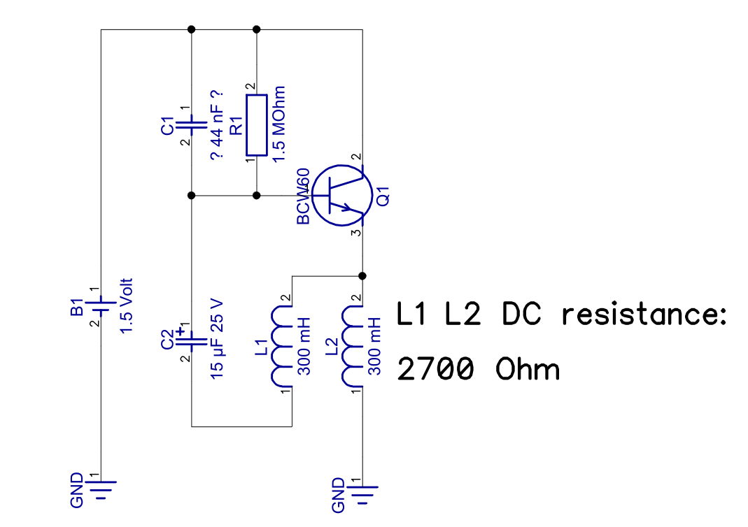
C1 1 ? 4 nF ? 2 R1 1.5 MOhm 2 BCW60 Q1 2 3 B1 1 1.5 Volt 2 C2 15 uF 25 V 2 1 L1 30 mH 1 L2 30 mH 2 L1 L2 DC resistance: 270 Ohm 1 GND 1 GND
in „Messung an einem Pendel mit elektromagnetischem Antrieb“ · Mikrocontroller und Digitale Elektronik · · Schaltpläne