-
Bild
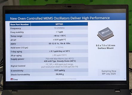
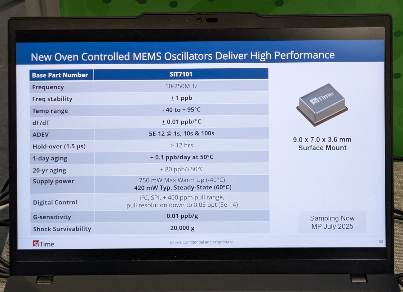
Foto eines Laptops mit Spezifikationen zu MEMS Oszillatoren
New Oven Controlled MEMS Oscillators Deliver High Performance Base Part Number SIT7101 Frequency 10-250MHz Freq stability + 1 ppb Temp range - 40 to + 95°C dF/dT + 0.01 ppb/°C ADEV 5E-12 @ 1s, 10s & 100s Hold-over (1.5 µs) > 12 hrs 1-day aging ± 0.1 ppb/day at 50°C 20-yr aging ± 80 ppb/+50°C Supply power 750 mW Max Warm Up (-40°C) 420 mW Typ. Steady-State (60°C) Digital Control I2C, SPI, + 400 ppm pull range, pull down to 0.05 ppt (5e-14) G-sensitivity 0.01 ppb/g Shock Survivability 20,000 g 9.0 x 7.0 x 3.6 mm
in „SpaceTechExpo, Tag 2 – Bauteile, Bauteile, Bauteile“ · Mikrocontroller und Digitale Elektronik · · Fotos
-
PDF
Slkor_SL9061.pdf
-- 18 May 2021 SL9061 3.4 Electrical Characteristics For Vs = (V+) - (V-) = 5V at Ta = 25°C, RL = 10kΩ connected to Vs/2, Vcm = Vs/2, and Vout = Vs/2 (unless otherwise noted). Table 5 Electrical Characteristics Symbol Parameter Test condition Min Typ Max Unit Vs Supply voltage (V+) - (V-) 1.5 5.5 V
in „LWL Schnittstelle Halb-Duplex (nur ein LWL!)“ · Analoge Elektronik und Schaltungstechnik ·
-
Bild
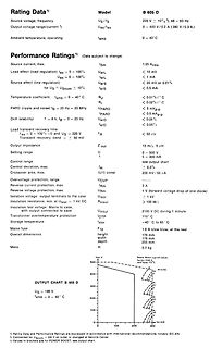
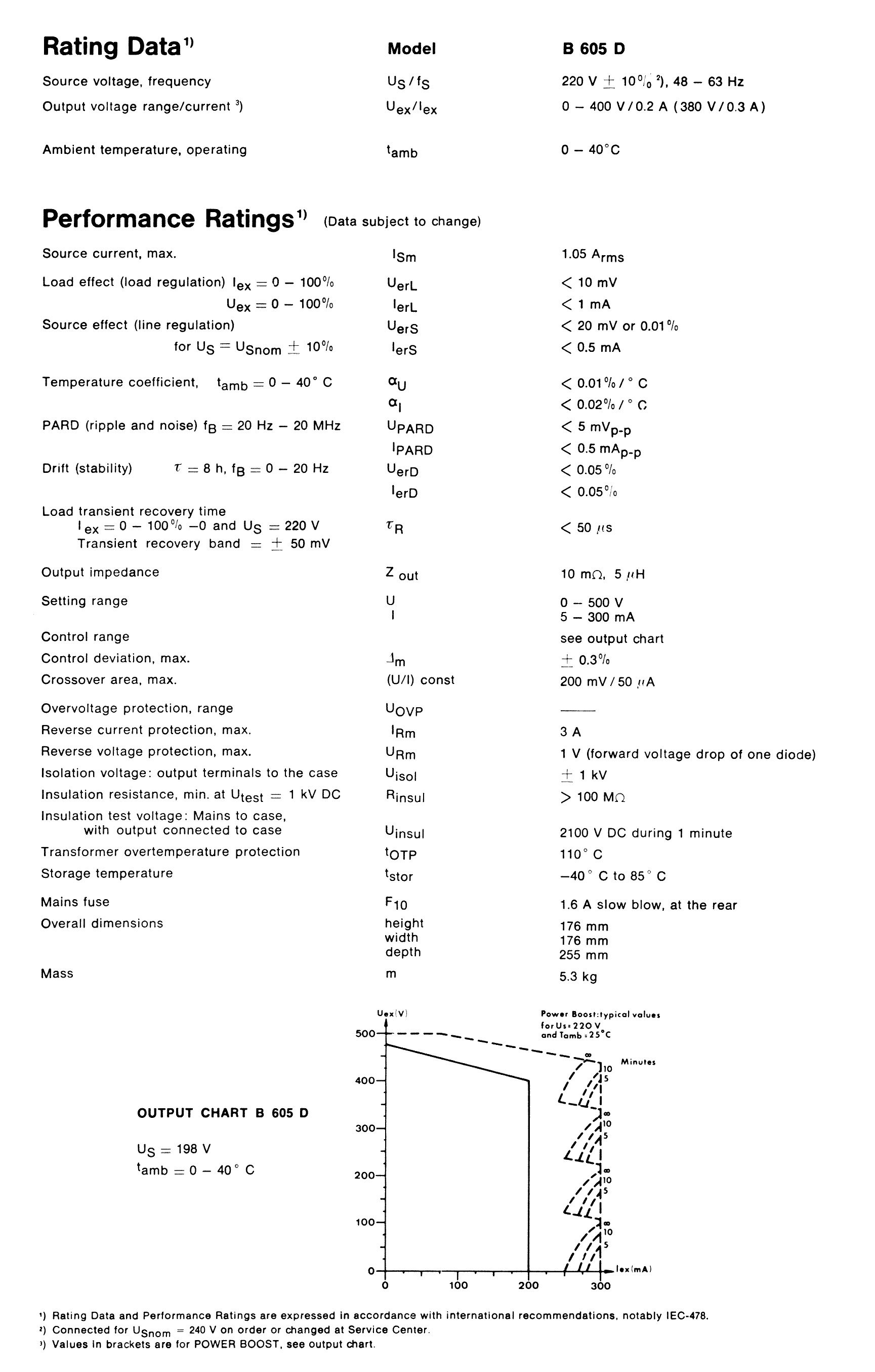
Datenblatt mit technischen Spezifikationen eines Netzteils
Rating Data B 605 Source voltage, frequency US/IS 220 V + 10% 48 - 63 Hz Output voltage range/current Uex/Iex 0 - 400 V/0.2 A (380 V/0.3 A) Ambient temperature, operating tamb 0 - 40°C Performance Ratings Uex/Iex Source current, max. Ism 1.05 Arms Load effect
in „[S] Suche Schaltbild zu Netzteil OLTRONIX B605D (400V / 200 mA)“ · Markt · · Screenshots
-
Bild
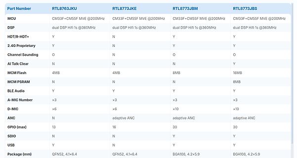
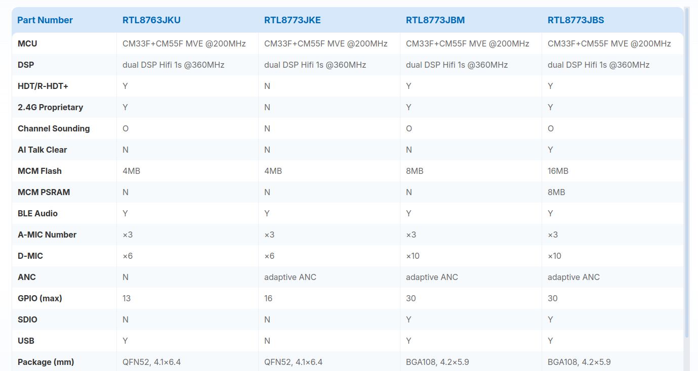
Vergleichstabelle verschiedener RTL-Mikrocontroller-Modelle
MCM Flash 4MB 4MB 8MB 16MB MCM PSRAM N N N 8MB BLE Audio Y Y Y A-MIC Number x3 x3 x3 D-MIC x6 x6 x10 x10 ANC N adaptive ANC adaptive ANC adaptive ANC GPIO (max) 13 16 30 30 SDIO N N Y Y USB Y N Y Y Package (mm) QFN52, 4.1x6.4 QFN52, 4.1x6.4 BGA108, 4.2x5.9 BGA108, 4.2x5.9
in „Realtek-Mikrocontroller mit Bluetooth 7, preiswerter nRF54, GMSL2 für Raspberry Pi uvam“ · Mikrocontroller und Digitale Elektronik · · Screenshots
-
PDF
GPS-Compendium_Book__GPS-X-02007_.pdf
Time of Week div., pa- 30 bits reserved 30 bits (TOW) ID 0.6s amble rity 0.6s rity 1 2 3 4 5 6 7 8 9 10 Word No. Subpage 300 Bits L W Data Word content 6s T H Sub-frame 1 Sub-frame 2 Sub-frame 3 Sub-frame 4 Sub-frame 5 Frame 1 2 3 4 5 6 7 8 9 10 1 2 3 4 5 6 7 8 9 10 1 2 3 4 5 6 7 8 9 10 1 2 3 4 5 6 7 8 9 10 1 2 3 4 5 6 7 8 9 10 (page) MW Satellite clocMW M W M WPartial almanaM W 1500 bits TH and health datTHEphemeris T Hphemeris T Hother data T H Almanac 30s Navigation message 1 2 3 4 5 6 7 8 9 10 11 12
in „Verschlüsselte Militär(?)daten innerhalb des GPS-Signals“ · HF, Funk und Felder ·
-
PDF
PCF7922ATT.pdf
”, PAM = ‘10’ -45 dBm Power Amplifier, XEN = 1, TXON = 1 at 25°C, Note 4 2015 May 11 68 Confidential NXP Semiconductors Product Specification KEECART PCF7922ATT SYMBOL PARAMETER CONDITION MIN TYP MAX UNIT POUT Output
-
PDF
technical.pdf
· (A − 2) Y13 = Y 31= Y 24 = Y 42= (10.122) D Y = Y = Y = Y = B ·C (10.123) 14 41 23 32 D (10.124) with A = k · (1 + exp(j ·2φ)) (10.125) B = 2· 1 − k2 (10.126) C = 2·k · exp(j ·φ) (10.127) 2 2 D = Z ref · A − C (10.128) (10.129) whereas
-
Bild
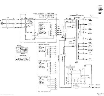
Schaltplan eines Power Modules und Transformators
SHOWN IN 120V POSITION WHT-GRA N HP PART NO 5020-B122 EARTH LINE NEUTRAL FRONT (REAR PANEL) LINE V +5-10% 48-66 Hz 250 VA MAX PRINTED CIRCUIT LINE SELECTOR SHOWN FOR 120V OPERATION E,C D,E PRINTED CIRCUIT LINE SELECTOR SHOWN FOR 220V OPERATION E,C D,E PRINTED CIRCUIT LINE SELECTOR SHOWN FOR 240V OPERATION
in „HP 5345A Frequenzzähler, Primärsicherung brennt durch“ · Analoge Elektronik und Schaltungstechnik · · Schaltpläne
-
PDF
Modulkarte__2_11_07__Netzeinschub_regelbar.pdf
1• 1 1i 1 1 1 1 ~ c0-24V \1 , 1 , t . , "'M "· ~'1 , - - - - -, ' ~ J ' ' 1 Vli"i p:) - V1~ 19 V14 10 -- ~-l-----(1··r-- 1 -) \ (.4 c- -J J - .~·:v' 1 IV/ l 1 1;':::J •:;2!~,,·~ 1 ~ ~t - ijr 1 1 /1\ 1 -<J· (11v / '\;rj 1 ,... '! 1 ~ / [1'~ f" [l 10 1 1; 1 · · . ' 'C>/ /' -j 1 1 11~ ...... r\10 • 1 ?.
in „suche Infos zu Trafo aus der KE-Ausbildung (Bundespost)“ · Analoge Elektronik und Schaltungstechnik ·
-
Datei
whisperVAD.py
your microphone properties !!! device_id = 7 samplerate = 16000 frame_duration = 30 # ms (must be 10, 20 or 30 for webrtcvad) vad_mode = 2 # 0=very permissive, 3=very strict # ---------------------------------------- model = whisper.load_model("base") vad = webrtcvad.Vad(vad_mode) q = queue.Queue()
in „KI Modell mit Spracherkennung“ · PC Hard- und Software ·
-
PDF
Magazin_Bauteile.pdf
0,30 2 0 Widerstand 620k 0,030 0,00 3 10 Widerstand 680k 0,030 0,30 30 Widerstand 680k 5% 0,25W 0,030 0,90 3 10 3 1 0 Widerstand 750k 0,030 0,00 2 10 Widerstand 820k 0,030 0,30 3 0 Widerstand 910k 0,030 0,00 3 10 4 1 10 Widerstand 1M 0,030
-
PDF
Merkblatt_-_baus._Steuerungssysteme_fuer_WAREMA_Sonnenschutzbehaenge.pdf
Bauseitige Steuerungssysteme für WAREMA Sonnenschutzbehänge Für künftige Verwendung aufbewahren! Gültig ab 10. November 2008 Allgemeines In Sonnenschutzbehängen mit 230V AC Stan- dardantrieben werden Asynchron-Kondensator- motoren eingesetzt. Hierfür müssen Sie nachfol- gende Punkte zwingend berücksichtigen:
in „Ausschaltverzögerung für ein Relais“ · Analoge Elektronik und Schaltungstechnik ·
-
Bild
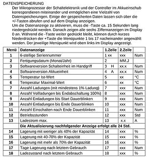
Tabelle der Menüpunkte einer Datenanzeige
Endabschaltung 100% | 8 | xxx | Num 9 | Anzahl Entladungen bis Start Dauerblinken | 9 | xxx | Num 10 | Anzahl Entladungen bis Ende Dauerblinken | 10 | xxx | Num 11 | Anzahl Einschalten nach Ende Dauerblinken | 11 | xxx | Num 12 | Betriebsstudium | 12 | xxx | Std 13 | Ladestrom max. | 13 | X.x | A Die
in „Tauchlampe Hartenberger mini compact LCD?“ · Mikrocontroller und Digitale Elektronik · · Screenshots
-
Bild
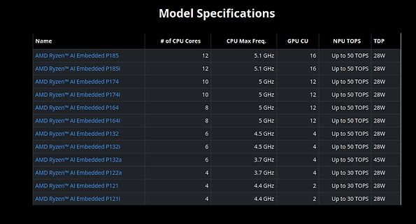
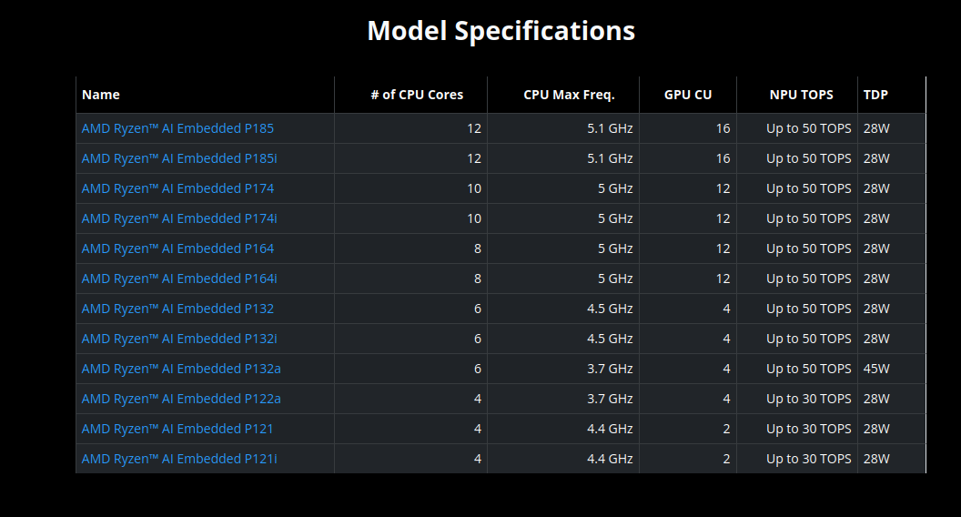
Tabelle mit AMD Ryzen AI Embedded Spezifikationen
Model Specifications Name # of CPU Cores CPU Max Freq. GPU CU NPU TOPS TDP AMD Ryzen™ AI Embedded P185 12 5.1 GHz 16 Up to 50 TOPS 28W AMD Ryzen™ AI Embedded P185i 12 5.1 GHz 16 Up to 50 TOPS 28W AMD Ryzen™ AI Embedded P174 10 5 GHz 12 Up to 50 TOPS 28W AMD Ryzen™ AI Embedded P174i 10 5 GHz 12 Up to 50 TOPS 28W AMD Ryzen™ AI Embedded P164 8 5 GHz 12 Up to 50 TOPS 28W AMD Ryzen™ AI Embedded P164i 8 5 GHz 12 Up to 50 TOPS 28W AMD Ryzen™ AI Embedded P132 6 4.5 GHz 4 Up to 50 TOPS 28W
in „Arduino Ventuno Q, Marktanalyse des Embeddedbereichs, neue Chips uvam“ · Mikrocontroller und Digitale Elektronik · · Screenshots
-
Bild
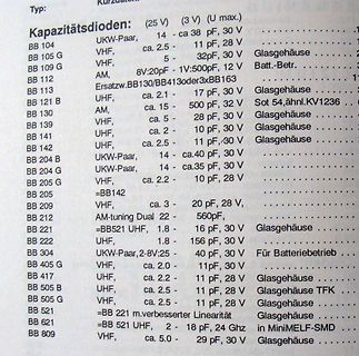
Tabelle von Kapazitätsdioden Typen und Spezifikationen
Typ: Kapazitätsdioden: (25 V) (3 V) (U max.) BB 104 UKW-Paar, 14 - ca 38 pF, 30 V BB 105 G VHF, ca. 2.5 - 11 pF, 28 V BB 109 G VHF, 5 - 32pF, 30 V Glasgehäuse BB 112 AM, 8V:20pF - 1V:500pF, 12 V BB 113 Ersatzz. BB130/BB413 oder 3x BB163 Batt
in „Liste gängiger Kapazitätsdioden“ · HF, Funk und Felder · · Screenshots
-
Bild
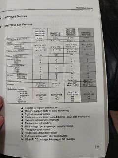
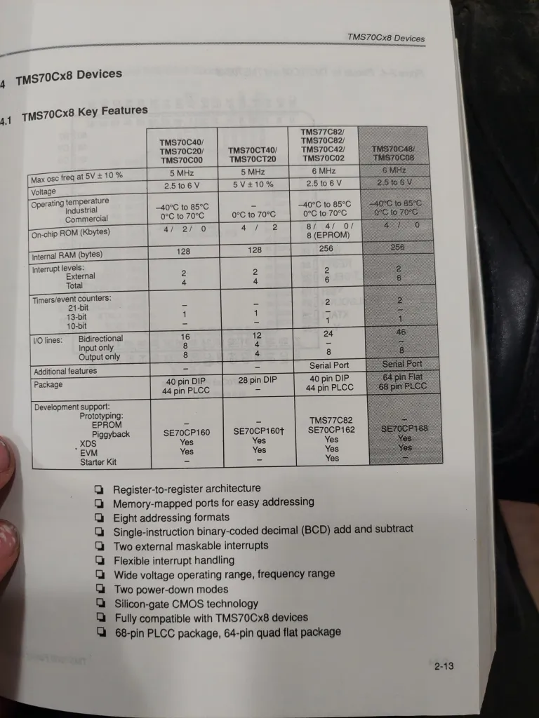
Tabellarische Übersicht der TMS70Cx8 Mikrocontroller-Merkmale
TMS70Cx8 Devices 4.1 TMS70Cx8 Key Features TMS70C40/TMS70C20/TMS70C00 Max osc freq at 5V ± 10% 5 MHz Voltage 2.5 to 6 V Operating temperature Industrial Commercial -40°C to 85°C 0°C to 70°C TMS70CT40/TMS70CT20 5 MHz 5V ± 10% 128 Internal RAM (bytes) 128 256 256 TMS70C82/TMS70C82
in „TMS70C08FNL Datenblatt“ · Mikrocontroller und Digitale Elektronik · · Fotos
-
PDF
MAT14.pdf
..........9 Changes to Ordering Guide............................................................9 10/10—Revision 0: Initial Version Rev.A | Page 2of 12 MAT14 SPECIFICATIONS ELECTRICALCHARACTERISTICS T = 25°C, unless otherwise specified. A Table 1. Parameter Symbol TestConditions/Comments Min Typ Max
in „Transistorarray mit 3 differentiellen (NPN) Pärchen gesucht.“ · Analoge Elektronik und Schaltungstechnik ·
-
PDF
CM7N65F.pdf
S´epT yð {&S÷ mK ÕgaNö SUOM g▯\▯ QxW g▯Y’ o▯n Qßz u5SB VDSS VGS0VÿID=250A… 650 V ▯‘▯u5 ; RDSON VGS10VÿID=3.5A 1.1 1.4 Ω ▯P<u5S VGS TH DSVGS▯D =25A▯… 2 4 V o▯n o▯u5mA IDSS VDS650V▯GS0V 25 ▯A h▯n o▯u5mA IGSS VGS ± 30V ▯100 ▯An * n o▯N g {¡kc VSDS IS7AÿVGS0V 1.5 V Qse›^ö ßeö ô d(off)DD300VÿD =7.0A 26 ns RG=4.7ΩVGS10V VGS0VÿVDS25V Qeu5[„ Ciss f=1.0MHZ 1380 pF ÿ ▯ †P"30us,2%d" ÿ ▯L=10ID=7J = 25!▯ W0W@ÿ▯mæW3^▯[ [ S:e°[ 3W S uYNÙN0ÿ5279516 ONwV0529799515 {1 u2013 rH R ▯C ▯M ▯7 ▯N ▯6 ▯ mæW3^▯fv[üu5[Pg PQlSł ▯w▯▯w▯▯j▯
in „Schaltnetzteil aus LED Deckenleuchte“ · Analoge Elektronik und Schaltungstechnik ·
-
Bild
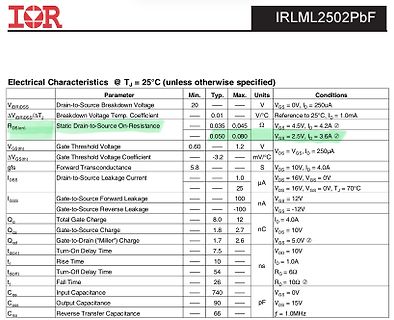
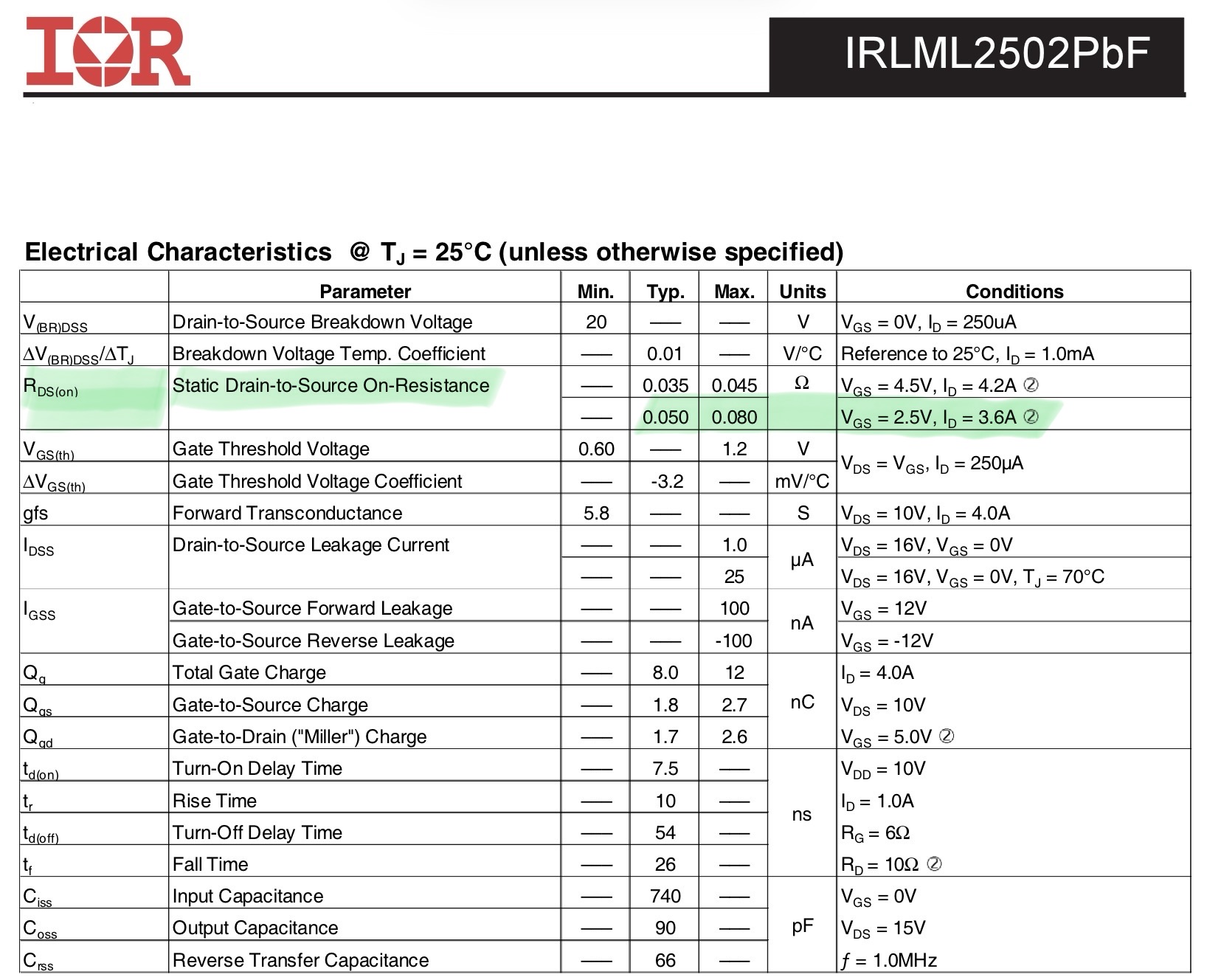
Elektrische Kennwerte eines IRLML2502PbF MOSFETs
IRLML2502PbF Electrical Characteristics @ TJ = 25°C (unless otherwise specified) Parameter Min. Typ. Max. Units Conditions V|BRDSS Drain-to-Source Breakdown Voltage 20 — — V VGS = 0V, ID = 250uA ΔV|BRDSS/ΔTJ Breakdown Voltage Temp. Coefficient — 0.01 — V/°C Reference to 25°C, RDS(on) Static Drain-to-Source
in „ESP32 mit 3,3V PWM einen 3,7V Motor betreiben“ · Analoge Elektronik und Schaltungstechnik · · Screenshots
-
PDF
RTK_031.pdf
conductor 1 (>100%) AL/PET/AL Copper Foil Copper Foil Copper Foil Outer conductor 2 0.1 x 16 x 7 0.10 x 16 x 5 0.08 x 16 x 10 0.14 x 16 x 5 Outer dia. (mm) 3.2±0.1 3.0±0.2 3.8±0.3 5.6±0.3 Max. Conductor resistance (Ohm/km) 48 85 33.3 15.9 Capacitance at 1 kHz (nF/km) 85±4 89±4 86±4 86±4 Characteristic
in „Suche passenden RP SMA Stecker zum crimpen“ · Mechanik, Gehäuse, Werkzeug ·
-
PDF
Hameg_HM303-6_Service_manual.pdf
Component Tester Bandwidth: 2 x 0 to 35MHz (-3dB) Test Voltage: approx. 7V (open circuit) Rise Time: ‹10ns Test Current: max. 7mA rms (short-circuit) Overshoot: max. 1% rms Deflection Coefficients: 1-2-5 Sequence Test Frequency: approx. 50Hz 1mV/div. – 2mV/div.: ± 5% (Bandwidth 0 – 10MHz (-3dB)) Test Connection
in „Hameg 303-6 Schaltplan + PCB.“ · Analoge Elektronik und Schaltungstechnik ·
-
PDF
moxa-eds-405a-series-datasheet.pdf
256 MAC Table Size EDS-405A, EDS-405A-EIP/MM-SC/MM-ST/PN/SS-SC models: 2 K EDS-405A-PTP models: 8 K Max. No. of VLANs 64 Packet Buffer Size 1 Mbits Priority Queues 4 VLAN ID Range VID 1 to 4094 Serial Interface Console Port RS-232 (TxD, RxD, GND), 10-pin RJ45 (115200, n, 8, 1) DIP Switch Configuration
in „[V] Diverse Moxa Industrie Switche und Access Points“ · Markt ·
-
Datei
Neuron.vhd
11; --Weight Memory Size DATA_WIDTH : integer := 16; --Float16 Format PAGE_WIDTH : integer := 4; --max. 16 Layers INPUT_WIDTH : integer := 7; --max 128 Input Signals INPUTS : integer := 10; --Number of used inputs LATENCY : integer := 6); Port ( --Control Signals clk : in std_logic; reset : in std_logic
in „Pipeline MAC-Unit: Problem mit Latency“ · FPGA, VHDL & Co. ·
-
Datei
Neuron.vhd
11; --Weight Memory Size DATA_WIDTH : integer := 16; --Float16 Format PAGE_WIDTH : integer := 4; --max. 16 Layers INPUT_WIDTH : integer := 7; --max 128 Input Signals INPUTS : integer := 10; --Number of used inputs MULT_LATENCY : integer := 6; --make shure: Latency < inputs! ADD_LATENCY : integer := 6
in „Pipeline MAC-Unit: Problem mit Latency“ · FPGA, VHDL & Co. ·
-
Datei
philipsPM-LCDs.txt
ansteuerbar, davon sind 160-3=157 genutzt: BP0 BP1 BP2 BP3 Pin S00 ={DC} ~{AC} DELAY SEQU 46 S01 BURST MAX delta% AX+B 45 S02 READ MIN LIM CAL 44 S03 ??? 4W{ire} SPEAKER SHIFT 43 S04 --- HF {diode} 2W{ire} 42 S05 P8P9 Z {up} {down} 41 S06 D9 c9 A8 b9 40 S07 k9 G9 h9 j9 39 S08 i9 l9 m9 g9 38 S09 d9 e9 a9 f9 37 S10 D8 c8 A8 b8 36 S11 k8 G8 h8 j8 35 S12 i8 l8 m8 g8 34 S13 d8 e8 a8 f8 33 S14 Z14 Z15 Z17 Z16 27! S15 Z13 Z12 Z10 Z11 26 S16 Z6 Z7 Z9 Z8 25 S17 Z5 Z4 Z2 Z3 24 S18 d7 c7 a7 b7 31! S19 P7 e7 f7 g7 30 S20
in „Pjilips PM2519“ · Markt ·
-
PDF
JDY-40-English.pdf
AT+CLSS 8 GPIO8 Input/output IO, which can be configured by AT+CLSS 9 VCC Power Supply(2.2V–3.6V) 10 RXD Serial port input pin 11 TXD Serial port output pin 12 SET AT command switching pin (low level AT instruction, high level transparent transmission) 13 CS CS chip select pin (low level of awaken,
in „AVR Programmübertragung wireless“ · Softwareentwicklung ·
-
PDF
AN1543-D.PDF
Emitter breakdown voltage, and by the amount of feedback, associated to the V , in the Base/Emitter N B 10 turns BE(on) network on the low end. The wire diameter can be derived from the maximum AssumingaV BE(on)of 1.10 V max and a 1.0 V drop in the current density of 4.50 A/mm2, or can be selected from the
in „Reparatur EVG für T5 Röhre“ · Analoge Elektronik und Schaltungstechnik ·
-
Bild
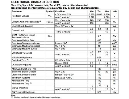
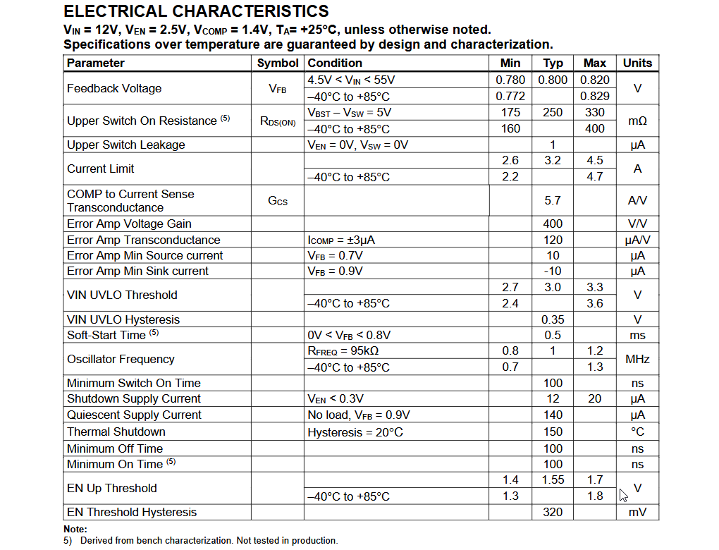
Tabelle der elektrischen Eigenschaften eines Bauteils
temperature are guaranteed by design and characterization. Parameter | Symbol | Condition | Min | Typ | Max | Units Feedback Voltage | VFB | 4.5V < VIN < 55V | 0.780 | 0.800 | 0.820 | V | | -40°C to +85°C | 0.772 | | 0.829 | Upper Switch On Resistance (5) | RDS(ON) | | 175 | 250 | 330 | mΩ | | -40°C to +85
in „Kollektorschaltung statt KFZ Relais“ · Analoge Elektronik und Schaltungstechnik · · Screenshots
-
Datei
EmulatorPIC16F84.py
>> 7) & 0x07 # Bit-Nummer f = instruction & 0x7F # File Register Address opcode = (instruction >> 10) & 0x03 value = self.read_ram(f) bit_mask = 1 << b if opcode == 0x00: # BCF f,b self.write_ram(f, value & ~bit_mask) elif opcode == 0x01: # BSF f,b self.write_ram(f, value | bit_mask) elif opcode ==
-
PDF
SA612A.PDF
4.5V U 5.25 R I C F Y 2.50 S 5.00 L O P 2.25 N 4.75 U S 2.00 4.50 1.75 4.25 4.00 1.50 –40 –30 –20 –10 0 10 20 30 40 50 60 70 80 90 –40 –30 –20 –10 0 10 20 30 40 50 60 70 80 90 O O TEMPERATURE C TEMPERATURE C SR00108 SR00111 Figure 10. I CC vs Supply Voltage Figure 13. Noise Figure RF1= 45MHz, IF = 455kHz
in „Langwellen Minimal SDR mit sa612 und SI5351“ · HF, Funk und Felder ·
-
Artikel
STM32
auf Debugging von max. 32KB Code limitiert, keine Limitierung beim Complilieren) Rowley Crossworks (Demo 30 Tage unbeschränkt, 150$ für nichtkommerzielle Nutzung, auf GCC basierend). Mir ist nicht klar warum man für diese
10-Polig auf Standard JTAG 20 Polig mit TTL/V24 Wandler. Siehe hier. Hardware-Beschaltung. Der STM32 benötigt für den Betrieb nur (Minimalbeschaltung): VCC 2..3,3V (je nach Typ) AVCC 2..3,3V (sehr wichtig
Artikel ·
-
Artikel
Optokoppler
deutlich steigen, allerdings auf Kosten der Empfindlichkeit. Geläufige Typen. Bezeichnung Gehäuse Vce (max) [V] Vsupply [V] CTR [%] Iout [mA] Geschwindigkeit Bemerkung Lieferant Datenblatt 4N25 4N26 4N27 4N28 DIP6 30 — 20, 10 ton/off 2 µs (typ.) B C D DK e F U R Broadcom CT-Micro Everlight Isocom LiteOn
zur LOC-Serie linearer Optokoppler Vollintegrierte Optokoppler. 6N137: 1-fach Typ, DIL8, Highspeed 10 Mbit/s H11L1: 1-fach Typ, DIL6, Highspeed 1 Mbit/s HCPL-2200: 1-fach Typ, DIL8, Highspeed 2,5 Mbit/s HCPL 2630: 2-fach Typ, DIL8, Highspeed 10 Mbit/s Alternative Technologien. Für höhere Geschwindigkeiten
Artikel ·
-
PDF
Sinuswechselrichter.pdf
GND GND U-OUT1 3.01K 4 13 L2-DRV 8 K H1PWM 8 11 U-REF 9 1 R165 R131 PWM2 5 12 BRDG-OUT1 1 0 INV-EN9 10 I-SWITCHING R166 R 2 PWM1 6 11 L1-DRV R 6 3 2 10.0K 10.0K 7 10 INV-EN R126 2 1 1K GND C95 R129 8 9 1.00M 5 V H1PWM 49.9K 2 0 1 L1PWM 1nF GND C88 R 1 GND 470pF GND GND R1 I-SWITCHING u 9 GND C96 C64 0
in „Wechselrichter Spannung und Frequenz steuerbar für Teichpumpe“ · Haus & Smart Home ·
-
PDF
Call-in-Verzoegerung_fuer_Variac_anfordern_-_Forum_-_Circuits_Online.pdf
klein genug, oder sollte ich Anpassungen vornehmen, wenn ich das Omron-Relay verwende? Und auch die 10A des Schalterkontakts. Befolge ich es, um eine 10AT-Sicherung für F1 zu nehmen? Oder sollte es eine Stufe tiefer gewählt werden? (/forum/file/80395) Rbeckers (/forum/user/23732) Gestorben Montag 7 Februar
in „Stelltrafo reo Anschluss“ · Analoge Elektronik und Schaltungstechnik ·
-
Artikel
Avr-gcc Bugs
12.4 99184 Wrong rounding in double to 32-bit and 16-bit integer conversions in libgcc. 12.3, 11.4, 10.5 90706 Useless code generated for stack / register operations 12.3 92729 Switch from cc0 to CCmode so avr-gcc can be kept in GCC v11+ 11.0 82658 Right-shifting 8-bit unsigned integers. 10.0 92055 Support
18037 fixed-point support 4.8.0 53344 Assemble 3-byte symbols 4.8.0 55974 Wrong suffix for __INT24_MAX__, __UINT24_MAX__ with -mint8 4.7.3 55897 Allocate __memx data to .progmemx.data 4.7.3 55243 [ada] STAMP variable is not defined in t-avr 4.7.3 50293 -flto fails if GCC is installed in directory with
Artikel ·
-
PDF
ONJU_Schematic.pdf
LED5 3V3 10 0101JIP 14V CR3 GND 10 kOhms CLE1 VDD PLE201 VDD PILD30 VDD PLE41 VDD PIED01 CLD FH34SRJ-10S-0.5SH(50) PR LED1 LED6 RGB_CTRL PIE0DIN DOUT PLD2 PIED0 DIN DOUT PLE202 PLE34 DIN DOUT PILD30 PIED04DIN DOUT
in „Bitte um Review meiner erweiterten ONYU-Schaltpläne (Bluetooth-Erweiterung mit CSR8635)“ · Mikrocontroller und Digitale Elektronik ·
-
Datei
sr595_lauflicht_1.ino
define DATA_PIN 11 // DS (Serial Data) #define CLOCK_PIN 12 // SHCP (Shift Clock) #define LATCH_PIN 10 // STCP (Latch/Storage Clock) #define POT_PIN A0 // Potenziometer an Analog Pin 0 #define DIP1_PIN 2 // DIP-Schalter Pin 1 #define DIP2_PIN 3 // DIP-Schalter Pin 2 // Objekt der Klasse shiftreg595 erstellen
in „Schulnotenbewertung eines Arduino-Programms“ · Mikrocontroller und Digitale Elektronik ·
-
PDF
LTH301-05.pdf
Collector Current 20 mA Transistor Power Dissipation 75 mW IR Diode Peak Forward Current (Pulse Wide = 10S, 300 pps) 1 A Diode Power Dissipation 100 mW Phototransistor Collector-Emitter Voltage 30 V Phototransistor Emitter-Collector Voltage 5 V Operating Temperature Range -25℃ to + 85 Storage Temperature
in „Relais durch Halbleiter ersetzen“ · Analoge Elektronik und Schaltungstechnik ·
-
Artikel
AVR-GCC-Tutorial
Wartezeit der Funktion _delay_ms() ist auf 262,14ms/F_CPU (in MHz) begrenzt, d.h. bei 20 MHz kann man nur max. 13,1ms warten. Die Wartezeit der Funktion _delay_us() ist auf 768us/F_CPU (in MHz) begrenzt, d.h. bei 20 MHz kann man nur max. 38,4µs warten. Längere Wartezeiten müssen dann über einen mehrfachen Aufruf
der Power-Down-Modus ausgeführt. (für andere AVR Controller siehe Abschnitt "Sleep-Mode") ISC11, ISC10 (Interrupt Sense Control 1 Bits) Diese beiden Bits bestimmen, ob die steigende oder die fallende Flanke für die Interrupterkennung am INT1-Pin ausgewertet wird. {| class="wikitable" ISC11 width="10%"
Artikel ·
-
Datei
Neuron.vhd
11; --Weight Memory Size DATA_WIDTH : integer := 16; --Float16 Format PAGE_WIDTH : integer := 4; --max. 16 Layers INPUT_WIDTH : integer := 7; --max 128 Input Signals INPUTS : integer := 10; --Number of used inputs MULT_LATENCY : integer := 6; --make shure: Latency < inputs! ADD_LATENCY : integer := 6
in „Pipeline MAC-Unit: Problem mit Latency“ · FPGA, VHDL & Co. ·
-
PDF
SOT363.pdf
dimensions (mm) 2.65 x 2.35 Footprint area (mm²) 6.23 Table 1. Package summary Symbol Parameter Min Typ Nom Max Unit D package length 1.8 - 2.1 2.2 mm E package width 1.15 - 1.25 1.35 mm A seated height 0.8 - 0.95 1.1 mm e nominal pitch - - 0.65 - mm e1 minimal pitch - - 1.3 - mm n actual quantity of termination
in „Bitte um Hilfe Bauteilsuche“ · Analoge Elektronik und Schaltungstechnik ·
-
PDF
LS902UT_int.pdf
benutzerspezifische Einstellungen: 20 Standardbildgrösse 346mm breit × 260mm hoch / 13.6" breit × 10.2" hoch Stromversorgung 100-240VAC, 50/60Hz, 2.5A Stromaufnahme 130W maximal bei normalen Gebrauch Power-Management-Modus: max. 5W Abmessungen, Gewicht 460 × 459 × 460.5mm / 18.1 × 18.1 × 18.1" (B ×
in „Erstinbetriebnahme CRT Monitor - Was ist zu beachten?“ · Analoge Elektronik und Schaltungstechnik ·
-
PDF
SPC-SWA-20N-Serie.pdf
an Zuverlässigkeit und Lebensdauer. Elektrische Eigenschaften Parameter Testbedingungen Min. Typ. Max. Einheit Spannungsgenauigkeit Ausgangsspannung ±1 % Restwelligkeit (pp) prozentual von Ua 1 % Temperaturkoeffizient ±0,02 %/°C Netzregelung ±0,5 % Lastregelung(Einfach Ausgang) Nennlast zu 1/10 Last ±0,5 % Lastregelung(Dual Ausgang) Nennlast zu 1/10 Last ±2 % Einsatzschwelle Überlast 110 % Isolationsspannung 1.500 VDC Isolationskapazität Einfach Ausgang 1.200 pF Dual Ausgang 350 pF Isolationswiderstand >1000 Mohm Wirkungsgrad 89 91 % Schaltfrequenz
in „Suche effizientes Schaltreglerboard von 55V zu 5V“ · Analoge Elektronik und Schaltungstechnik ·
-
Datei
adc_devel.ino
while(ADC1->CTLR2 & ADC_CAL) { } } }; uint16_t calc_spg(uint16_t adc_digit, uint16_t refvolt) { // 10-Bit ADC: max = 1023 // Ergebnis in 1/100 V, z.B. 3.45 V => 345 return ((uint32_t)adc_digit * refvolt) / 1023 / 10; } ADC analog1(PD4); ADC analog2(PA1); void setup() { Serial.begin(115200); printf("\
in „CH32V003 und Arduino“ · Mikrocontroller und Digitale Elektronik ·
-
PDF
Anleitung-Eurolite-SL-1200-search-light-de_en_es_fr.pdf
:!During!the!operation!the!housing!becomes!very!hot!!Danger!toecially life!!Do!not!open!for!10!minutes!after!switching!off.!Isolate!luminaire!from!all!poles!of!the!mains 1 2 3 4 56 7 8 9 10Test service!operations!only!by!authorized!dealers.!Replace!any!cracked!protective!shield.nce!and Digital
in „Eurolite SL-1200: Thermische Abschaltung nach 10 min (HMI-Lampe)“ · Analoge Elektronik und Schaltungstechnik ·
-
PDF
EWPH480-F_ENG.pdf
humidity: 30 ... 95 RH% without condensation instrument disconnecting device. Storage temperature: -10 ... +60 °C It's recommended, furthermore, to properly protect all the electric circuits connected to the instrument, with devices (ex. fuses) proportionate to the circulating currents. It's strongly
-
Artikel
RFM69
Amplitudentastung) Eingebauter Manchester de- und -encoder Frequenzbereiche 315, 433, 868, 915 MHz Max. Datenrate 300 kbit/s Ausgangsleistung +13 dBm (rund 20 mW) Stromaufnahme 45 mA senden (13 dBm), 16 mA empfangen, 0,1 µA Standby Integrierte Packetengine für Synchronwort, CRC, Scrambling und AES-Verschlüsselung
von Semtech == Vergleich zum RFM12B == RFM12B RFM69(C)W Versorgungsspannung 2,2 - 3,8 V 1,8 - 3,6 V Max. Datenrate 115,2 kbit/s 300 kbit/s Sendeleistung 5 dBm 13 dBm Empfindlichkeit -105 dBm -120 dBm Stromaufnahme 22 mA/11 mA/0,3 µA 45 mA/16 mA/0,1 µA FIFO Größe 16 Bit 66 Bytes Syncmustererkennung Fest
Artikel ·
-
Datei
Logo-lesen.ino
.address { font-size: 18px; color: #777777; margin-top: 10px; } .value { font-size: 90px; font-weight: bold; margin: 35px 0; } .status { display: inline-block; padding: 12px 20px; border-radius: 10px; font-size: 18px; } .connected { background: #d4edda; color
in „mit ESP32 LOGO 8 VM Block lesen“ · Mikrocontroller und Digitale Elektronik ·
-
PDF
FD6287T_fortiorEnglish.pdf
7 VCC Low-side supply voltage 8 WITH Grounding 9,10,11 LO3, LO2, LO1 Low-side output 12,15,18 VS3, VS2, VS1 High-side floating offset voltage 13,16,19 HO3, HO2, HO1 High-side output 14,17,20 VB3,VB2,VB1 High-side floating absolute voltage REV_Preliminary
in „hc-160a s2 Datenblatt?“ · Mikrocontroller und Digitale Elektronik ·
-
Bild
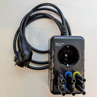
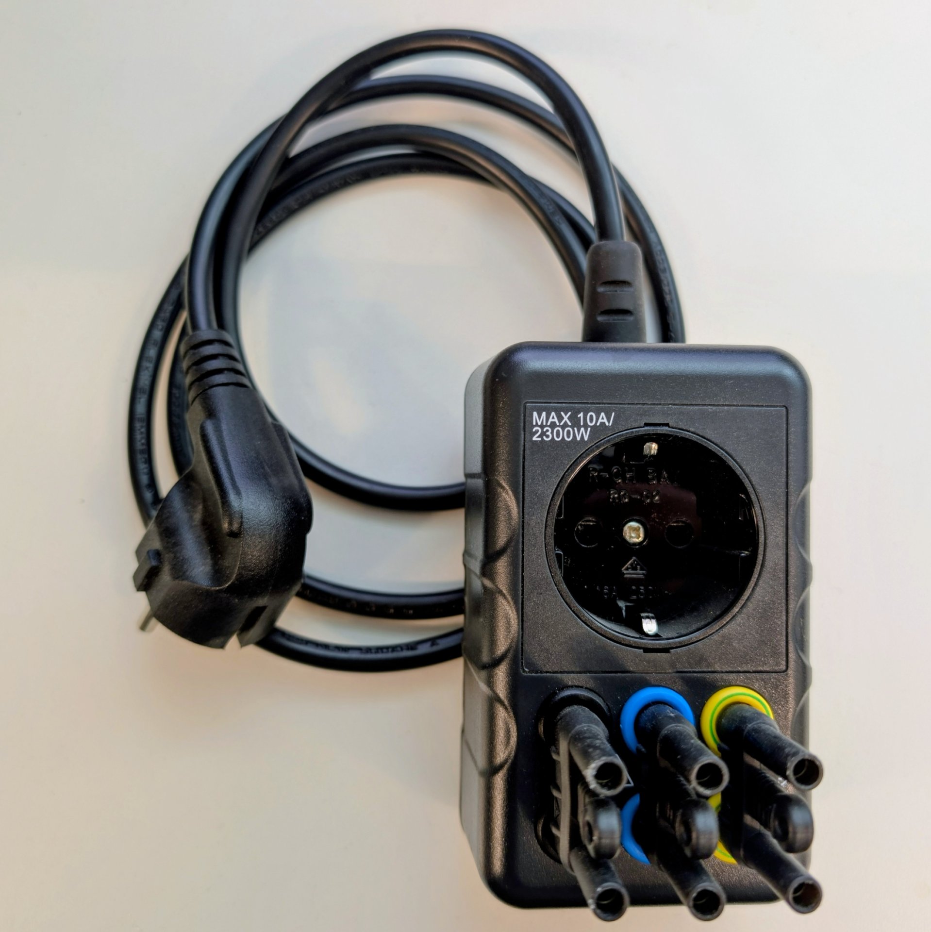
Reiseadapter mit Schuko-Steckdose und mehreren Steckplätzen
MAX 10A/ 2300W
in „[V] Schuko Voltcraft SMA-10 Messadapter“ · Markt · · Fotos