(SMU). SMM3000X features 6½-digit resolution, output capability of up to ±210 V DC voltage, ±3.03 A DC current, and ±10.5 A pulsed current, with programming and measurement resolution down to 10 fA / 100 nV, and a maximum acquisition rate of 100,000 points/s. [/c] ### SeeedStudio – 4.4GHz-VNA mit
. 7-Inch High-Definition Capacitive Touchscreen:Features a large 7-inch IPS LCD display with a resolution of 1024x600 and capacitive touch control. The bright screen ensures clear visibility even in outdoor environments, while the touch interface combined with
ich booten kann und nach dem Anmelden auf dem Desktop lande. Meine Grafikkarte: Intel Alder Lake-P GT1[HD Graphics], Kennung: 46a3. Im Ubuntu live-System wird offenbar der i915-Treiber verwendet. ich habe nun versucht das Problem mit KI-Hilfe (ChatGPT und Grok) zu lösen, aber hier dreht sich alles
Mir hat mal eine "HI" bei einem Treiber-Problem sehr geholfen: Daniel A. (daniel-a)
with safety development packages • Extended reliability with qualification up to 135 °C and a 10-year mission profile at 105 °C [/c] ### Analog Devices ADHV4710 - Operationsverstärker mit 1 A Ausgangsstrom und +/- 55 V-Fähigkeit. Dass Operationsverstärker nützlich sind, steht außer Frage
Produkt ins Rennen, dessen Ausgangsfähigkeit folgendermaßen beschrieben wird: [c] The ADHV4710 is a high voltage, high power, high speed operational amplifier optimized for driving up to ±1A at ±1300V/μs into capacitive and resistive loads. [/c] Neben dem vergleichsweise großen Gehäuse ist zu
Kauf an. PeakTech 1670 Digitalstellen: 50.000 Überspannungskategorie: CAT II 1000 V, CAT III 600 V AC/DC 1000A Die Stromzange ist quasi unbenutzt, aber 7 Jahre alt. Zustand sehr gut, absolut neuwertig. War ein Spaßkauf von privat, liegt aber nur bei mir rum. Preisvorstellung (VHB): 100
auch nicht gedacht, sondern für den Fahzeugbereich. Für den Hausgebrauch habe ich eine Benning CM P2.
habe mit LTspice ein Clock Signal eines LVC - Treibers simuliert. Vdd = 1,8 V Drive Strength = 9 mA Leiterbahn = 600 mm Wellenwiderstand 50 Ohm AC Terminierung = 33 pF & 50 Ohm Der Treiber hat 11,3 Ohm Innenwiderstand. Die Serienterminierung hat 39 Ohm. Das sind übliche Werte, nichts besonderes
überrascht. In Farbe Grün sieht man den Strom durch den Innenwiderstand Ri. Die Spitze liegt bei 45 mA. In Farbe Ocker sieht man den Strom durch die Serienterminierung Rs. Die Spitze liegt bei 12 mA. In Farbe Rot sieht man den Strom durch R1 in der AC Terminierung. Die Spitze liegt bei 9,5 mA.
163 226 RADIATION SOURCE : Ra 1000 SCINTILLATOR :NaI(Tl) 76 mm dia. × 76 mm t PMT :R1307 E 800 N N H 600 C K A P 400 200 0 200 400 600 800 1000 1200 1400 1600 1800 2000 ENERGY (keV) THBV4_0708EA Figure 7-8: Relation between peak channel and gamma-ray energy Amount of emission from a NaI(Tl) scintillator
headed by “Changes.” The keys have special functions for setting menu codes: u/w (12) = Increases a number by one with each press (the numbers change in cycles) =/z (14) = Confirms a code setting; stores a code setting and exits the menu p/p (11) = Moves to the next of the three numbers of a code (
akzeptierten Autoren ein Poster anzufertigen, in dem die Ergebnisse kurz vorgestellt werden. Üblich sind 600-800 Wörter auf A0, hier ist es zu einer "Bleiwüste " geraten, die aber IMHO durchaus lesbar ist. Ein Bezeichnung als "bescheuert" ist da völlig fehl am Platze. * https://de.wikipedia.org/wiki
trotzig. Die Kernaussage ist doch “Wir haben einen für uns gut funktionierenden Workflow mit Tool A geschaffen und den kann man mit Tool B nicht exakt nachbauen.” Deswegen ist Tool B aber nicht allgemein schlecht für z.B. FPGA Entwicklung. 1. Gerade bei Versionsverwaltung, Build-Systemen u.ä. ist
Kühlkörper. Die Adernbeschriftung passt genau. Nur der Leiter-Querschnitt gibt mir zu denken. Die 1000V, 15A kann ich ja noch glauben, aber ber der Minimalspannung von 250V, wäre der Strom ja dann viermal so hoch, das halten die Adern die in die vergossene Brücke führen eher nicht aus. Auf dem Mainboard (nicht
. Mit dieser habe ich sehr gute Erfahrungen: https://www.voelkner.de/products/1070391/Benning-CM-P2-Stromzange-digital-CAT-III-600-V-Anzeige-Counts-4200.html Zeigt ab 10-30mA auch DC-Ströme stabil an.
Embedded XPort Device Server BUILD NETWORK CONNECTIVITY INTO YOUR PRODUCTS, QUICKLY AND SIMPLY XPort is a compact, integrated solution to web-enable any device with serial capability. By incorporating XPort to a product design, manufacturers can offer network connectivity as a standard feature within weeks
= 3.6 V T 80 T l VCC = 3 V l 140 e 70 e VCC = 3.3 V D D i i 130 a 60 V CC = 3.3 V a V = 3 V a a CC p 50 V CC = 3.6 V p 120 r r P P i 40 o 110 - - t - w 30 h o i 100 r 20 r v v r r 90 D 10 D – – L 0 H 80 t –55 –40 0 25 70 85 125 t –55 –40 0 25 70 85 125 TA– Free-Air
≤ +125℃ 2.9 A POWER SUPPLY (1) V S 4.5V to 36V 117 145 Power Supply Rejection Ratio (PSRR) dB -40℃ ≤ T A +125℃ 115 V O 2.5V 450 600 Quiescent Current (Q ) μA -40℃ ≤ T A +125℃ 790 DYNAMIC PERFORMANCE Gain-Bandwidth
claimed as the property of others. STK5Q4U362J-E Advance Information Intelligent Power Module (IPM) 600 V, 10 A The STK5Q4U362J-E is a fully-integrated inverter power stage consisting of a high-voltage driver, six IGBT’s and a thermistor, suitable www.onsemi.com for driving permanent magnet synchronous
voltage for proper HO functionality 5 VCC V VS Steady state high side floating supply offset voltage -1 600 VCC Supply voltage VCCUV+ VCLAMP CC Supply current note 2 10 mA CT CT lead capacitance 220 — pF SD Shutdown lead current -1 1 I Current sense lead current -1 1 mA CS o TJ Junction temperature -40 125
nr_inodes=7531612,mode=755,inode64) devpts on /dev/pts type devpts (rw,nosuid,noexec,relatime,gid=5,mode=600,ptmxmode=000) tmpfs on /run type tmpfs (rw,nosuid,nodev,noexec,relatime,size=6555808k,mode=755,inode64) /dev/nvme0n1p2 on / type ext4 (rw,relatime) securityfs on /sys/kernel/security type securityfs
Linux man-pages 6.17 2026-02-08 strerror(3) ein@typ:~$ lsb_release -a No LSB modules are available. Distributor ID: Ubuntu Description: Ubuntu 26.04 LTS Release: 26.04 Codename: resolute [/code]
Signalformen darstellen. Im Bild das 1kHz Ausgangssignal einer digitalen Audioendstufe. Schaltfrequenz etwa 600kHz. Bild von einem Telequipment D67A aus den 1970ern. https://w140.com/tekwiki/wiki/Telequipment_D67
Modell. So sieht das gute Stück aus: https://museum.dantalion.nl/files/original/4d7e7d3833dc0c97b73a2f8fb5bfa8140b1735ee.jpg
CONDITIONS Min Typ Max UNIT AVOL Differential voltage gain, standard part 1 Gain 1 R L2k , V OUT=3V P-P 250 400 600 V/V Gain 22, 4 80 100 120 V/V RIN Input resistance Gain 11 4.0 k 2, 4 Gain 2 10 30 k 2 4 CIN Input capacitance Gain 2 2.0 pF I Input offset current 0.4 5.0 A OS BIAS Input bias current
Temperatur/Oberflächenwerte und ggf. ein grober HF-Check. Mein Gedanke wäre daher ein einfacher A/B-Test: A: Wohnung ruhig / nichts Auffälliges B: Ereignis läuft / Brumm, Knacken, Druck/Wärme spürbar Und dann parallel loggen: * Audio/Körperschall unter 100 Hz * ggf. Beschleunigungssensor
die hier: https://www.google.com/maps/place/Canal+St,+New+York,+NY,+USA/@40.7197972,-74.0066559,3a,75y,182.43h,97.75t/data=!3m10!1e1!3m8!1sBg2QP_IzCMuKxfuCl5xzqA!2e0!6shttps:%2F%2Fstreetviewpixels-pa.googleapis.com%2Fv1%2Fthumbnail%3Fcb_client%3Dmaps_sv.tactile%26w%3D900%26h%3D600%26pitch%3D-7.75%
V =4.5~5.5V, V =0V, unless otherwise specified) A DD SS Parameter Symbol Condition Min Tpy Max Unit Oscillation Frequency Fosc —— —— 800 —— KHz Transmission delay time tPLZ CL=15pF, DIN→DOUT, RL=10KΩ —— —— 300 ns Fall time t CL=300pF, OUTR/OUTG/OUTB
CA SK PL 200 GB AU HU BG CZ 150 FR KR WO EP 100 US JP >3000 Treffer 50 (aktuelle Diskussion J 0 E S P Trivialpatente!) KWOP 9 8 9 0 BCZR R < 1 1 9 9 9 3 4 A U G 1 1 1 9 9 9 6 7 P GBU 1 1 1 1 9 9 9 0 C SK L 1 1 1 0 0 0 3 DE A 2 2 2 0 0 0 RU !!! Korea / Japan !!! 2 2 2 Zunahme bei Patentanmeldungen zur
Sägezahnspannung S an den Eingang E des Symmetrierverstärkers angeschlossen. Dessen Ausgangsspannungen A1 bzw. A2 sollten in etwa die gleiche Amplitude aufweisen und jeweils einen Stellbereich von 120 mVss oder etwas mehr erreichen, wenn A1 und A2 mit den Eingängen A1 und A2 des Mischers verbunden sind.
VIN=3V E 80 VIN=5V VIN=3.7V VIN=12V 75 75 VIN=4.2V VIN=16V 70 70 0 200 400 600 800 1000 0 100 200 300 400 500 Load Current(mA) Load Current(mA) Line/Load Regulation Line/Load Regulation VOUT=5V VOUT=18V 5.5 19 V V e e l l V 5 V18 u u u u O VIN=3V O VIN=5V VIN=3.7V VIN=12V VIN=4.2V VIN=16V 4.5 17 0 200 400 600 800 1000 0 100 200 300 400 500 Load Current(mA) Load Current(mA) Operation Frequency vs. Input Voltage Operation Frequency vs. Input Voltage VOUT=5V VOUT=18V 1.3 1.3 1.2 1.2 z z H H y y n 1.1 n1.1 q
Die Kunst des Handwerkers besteht u.a. darin, vorhandenes Werkzeug fachgerecht einzusetzen. Oder z.B. den Einsatz je nach Faktenlage auch abzulehnen. Spätestens wenn ein Grobmotoriker das Gewinde im Zylinderkopf oder das des Messgerätes
Manfred P. schrieb im Beitrag #8025473: >> wenn man mit einem Kombigewinde einen Schlauch >> einsparen kann, wird man das machen. > > Na ja ... > > Als Eigenbau hatte ich eine Zündkerze ausgeräumt und
in V – V = 15 V to 125 V, I = 15 mA to 700 mA, P rated dissipation 0.5 5 A ADJ input current I O O Reference voltage VI– VO = 10 V to 125 V, IO = 15 mA to 700 mA, P rated dissipation, 1.2 1.27 1.3 V (OUT to ADJ) See Note 3 † Pulse-testingtechniques
Automatic Multimeter P M 2 5 1 9 Service M a n u a l ” 8 7 0 3 0 81 Eec-cutcSystems P H ]Li p S Automatic Multimeter ‘ S e r v i c e M a n u a l 7 0 3 0 8 p e t e ceeaekr s | SRE ao face acca ana tee S | ( a a c p alea<ea o aR i oN Spee cereresies Conk eked P R e s eae a a a i P eteeSs ae a me, Tieoaime| I M P O R T A N T “This service m a n u a l serie number D Y 01 9611 and o n w a r d s In chapter 9, modifications to the
With lead in the A — b u s V ~ ~ P O - t 4 m V +/— P O — t 4 m A - ~ P.O-t4 V +/— P.O—t4 m A / ~ PO.-t4 V +/— PO.—t4 mA , ~ P O - t .V4 : Hz P.O-t4 KHz A ~ ~ P.O—t4 WA PO.—t4 KHz ~ PO.—t4 pA P.O—t4 M H z ~ P,O-t4 m A ~
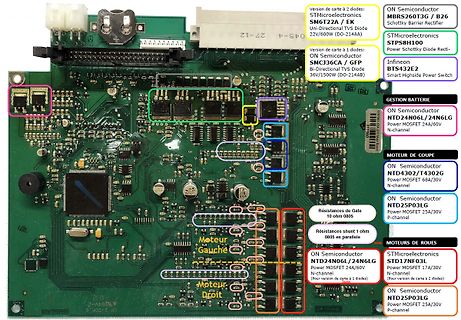
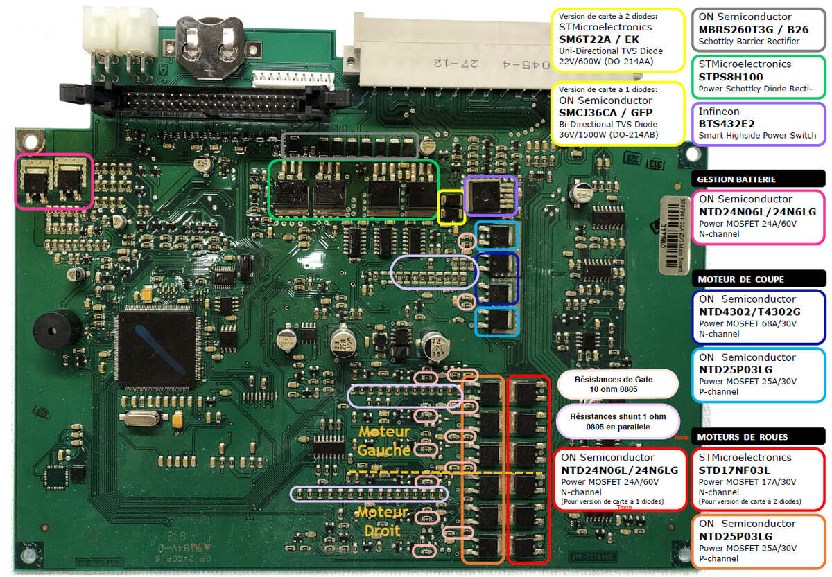
Infineon, BTS43E2, Smart Highside Power Switch, GESTION BATTERIE, NTD24N06L/24N6LG, Power MOSFET 24A/60V, N-channel, MOTEUR DE COUPE, NTD4302/T4302G, Power MOSFET 68A/30V, N-channel, NTD25P03LG, Power MOSFET 25A/30V, P-channel, MOTEURS DE ROUES, ST17NF03L, Power MOSFET 17A/30V, ON Semiconductor, NTD24N06L/24N6LG, Power MOSFET 24A/60V, N-channel, ON Semiconductor, NTD25P03LG, Power MOSFET 25A/30V, P-channel, Résistances de Gate 10 ohm, Résistances shunt 1 ohm 0805 en parallel, Moteur Gauche, Moteur Droit
to +85 °C Soldering temperature t ≤ 10 s, 1 mm from case T 260 °C sd Power consumption Tamb ≤ 85 °C P tot 10 mW Note • Stresses beyond those listed under “Absolute Maximum Ratings” may cause permanent damage to the device. This is a stress rating only and functional operation of the device at these or
a I 1 T 3 I R x t i I O e s i V S L k h o E R 0 i 1 T E G Z 1 0 w = k O C T I 1 ) r 1 P A z L B 3 n a V T C k V T p r O R 9 S 6 a I 9 T T 1 1 5 d 2 P 1 L C F a A k 5 1 0 µ P T 5 r D c i E 4 u l l p D R
/1.jpg) Bildquelle, alle: Autor ### Ceyear – 4GHz-MSO im Zulauf Ceyear arbeitet daran, tour a tour mehr der am Heimatmarkt erfolgreichen Messgeräte nach Europa zu bringen. Neu ist nun ein mit bis zu 4GHz arbeitendes Oszilloskop, das sich wie in den Abbildungen gezeigt präsentiert.  ### Liquid Instruments – FPGA-basierte Messtechnik für hohe Flexibilität FPGAs haben sich in diversen metrologischen Aufgaben gut etabliert. Im Hause Liquid
1 A C input/output capacitance - 2.6 5 pF io Select inputs A0, A1, A2; RESET V IL LOW-level input voltage 0.5 - +0.8 V V IH HIGH-level input voltage 2.0 - 5.5 V ILI input leakage current 1 - +1 A C input
— 220 — MIC2915x OUT = 750 mA — 350 600 MIC2915x OUT = 1.5A — 80 175 MIC2930x OUT = 100 mA — 250 — MIC2930x I = 1.5A OUT Dropout Voltage — 370 600 MIC2930x OUT = 3A ∆V = –1% (Note 5) mV OUT — 125 250 MIC2950x OUT = 250 mA — 250 — MIC2950x OUT = 2.5A — 370 600 MIC2950x OUT = 5A — 80 200 MIC2975x I = 250 mA OUT — 270 — MIC2975x OUT = 4A — 425 750 MIC2975x OUT = 7.5A MIC2915x OUT = 750 mA, — 8 20 V = V + 1V IN OUT — 22 — MIC2915x OUT = 1.5A — 10 35
event of The ability to withstand without its failure. conductivity due to condensa- tion. breakdown a 60 second appli Double - composed of both basic cation of a defined dielectric insu- and supplementary. Reinforced 3 - Frequent conductive pollution due to condensation. lation voltage between input
mate P11 Ground or LED signal If grounded, drive does not use deferred spin P12 Ground 1st mate P13 V12 12V power, pre-charge, 2nd mate P14 V12 12V power P15 V12 12V power Notes 1 All pins are in a single row, with a 1.27 mm (0.050 in) pitch. 2 The comments on the mating sequence apply to the case of backplane blindmate connector only. In this case, the mating sequences are: • the ground pins P4 and P12. • the pre-charge
2 0 C O C C O 0,84 c c c c o 0 14 3 0 (NOM261 c c a c a c c c c a ROW7 0 13 4 0 0 12 6 0 2,64 (0.1001 T. P. 0 11 6 0 (SeeNotec) 0 1 0 7 0 0 9 so 2,18 (0.0NOM 7,62. 0,25 (0.300 • 0.0101 PIN 1 ROW 1 PIN 2 R O W 3 P IN 3 R O W 6 PIN 4 ROW 7 & D.P. ANODE
Kennwerte Genauigkeit Klasse 1,5 Meßbereich 600 v— Innenwiderstand 120 kQ Messung Meßbereichschalter @ in Stellung „VX2/mA" (rot). Spannung an die roten Buchsen O und @ anlegen. Spannung auf der V-Skale ablesen; mit Faktor 2 multiplizieren. Es sind
: A and B Input Type Balanced, differential InputImpedance 100 kW per side in parallel with ≈ 300 pF (with no internal loads) Internal Load Impedance 600 W, 150 W or 200 kW, software selectable Vmax Internal
t r a a e P m r v a S e s < c a M o e k = n P D R s , t h r 0 i C F p r z > d a . 1 < r 1 4 t s r r n i i t t v E w r m e l u t r a t b = = a m P m u a v r S e d C c a M o A n e o n P D R e o y n h Z m C < 0 . 1 n 1 4 f r r g < s e s 2 t e m e 0 i e r a e p m - r r o r S l f e a M o z P D R s r e r i e w a m P a r C a P 454 143/37R 46 13.6 DMS card 13.7 Control output 13.8 Printer !! Error !! N J Parameter for Channel A Parameter for Channel A Value
lit. P5 Cooking sensor calibration P6 Frying sensor calibration 5.2.1.2 Without twist or tippad on the worktop P7 Indication of parameters P8 Life test In this case, a 0 is shown if the signal is correct. P9
das so üblich ist, Elkos raus und angucken, autsch https://www.fingers-welt.de/phpBB/viewtopic.php?p=67613&sid=496d5c6bd473e5a96e6ad5c59c004aab#p67613 2/21 17.03.26, 19:23 Reparaturerfolge - Seite 13 - Fingers elektrische Welt Da drunter sieht die Platine auch nicht mehr so ganz fabrikneu aus Wenn man

 Bild
Bild
 Bild
Bild