K2 Rk Hote C45 : suisos | 6 $7 10 54LSOb 01 2 O,lp | 6 54LS 139 mal : yo_¥i_Y2 Fie gti thy iS 8 Wp A gar mes ; Olp ype | Olp 4 50 mo , Op B | jpe5 3 Op zl +5V us 4% a! m a d low RU3 C43 = eis +5 | |lagt 1 Pin} 1S _|Pin owl ul 6 (2 ‘ 70! 12 |W ee 7[ 65,6 [1 19 7 ee : P maa: sets iy TERMB SULST wat ls n RD 10/M ct WR ce WR Timern 1S1 out 8155 Timer PAT PC3 | as Pc3 Ch 7] 1 3b 2 Lig Lol B j ka R1 C19 H C7 C1
USB-Hub entfällt ersatzlos.   Bildquelle: https://www.arduino.cc/product-ventuno-q Im Echtzeitbereich setzt die Platine auf einen STM32H5F5 – im Prinzip also ein Arduino Uno Q höherer Leistungsklasse
eigene Klassen hinzuzufügen. [/c] ### Lesestoff: AD-Frontends mit 7.5d Genauigkeit Für Freunde der Metrologie findet sich unter https://www.digikey.hu/en/articles/select-the-right-components-to-achieve-7-5-digit-measurement-resolution
Application modules fit in any of the open module slots Safe Torque Off Function Conforms to IEC61800-5-1, SIL 3 and EN954-1 Category 3 2.2-7ACont. 3.3-11.2APeak for machine safety and system cost reduction 2.2-42ACont. 3.8-73.5APeak Smartcard for Simple Set-up and Cloning 1.3-33.8ACont. 2.2-80.5APeak
Number Range Frequency Ranges Chip Select, allowing the host to service higher priority 25AA040 1.8-5.5V 1 MHz I interrupts. Also, write operations to the device can be 25LC040 2.5-5.5V 2 MHz I disabled via the write-protect pin (WP 25C040 4.5-5.5V 3 MHz I,E Package Types PDIP CS 1 8 VCC Features: 0
. Electrical VBUS circuit CC2 DM DP 3.3K C C GND 1 F 2 S D 1 M D 2 B N D C EP P 1uF R GND Figure 3. Application diagram WWW.FASTSOC.COM 5 FASTSOC MICROELECTRONICS CO., LTD FS312B Datasheet If the Type-C male connector is connected
;lin --> sin sts PWM3, AH cbi PORTB, 0 ;PWM1 mit Port B0 sbi PORTC, 0 ;PWM2 mit Port C0 cbi PORTD, 4 ;PWM3 mit Port D4 sbi PORTD, 5 ;PWM4 mit Port D5 ldi AL, LOW(M2P2) sts PWMAdrl, AL ldi AL, HIGH(M2P2) sts PWMAdrh, AL ret
und erst im Detail ermitteln muss, womit erst eimmal nicht klar ist, was passiert, wenn Bit 7 auf Port 4 gesetzt wird. Man kann das zwar herausbekommen, katalogisieren, dokumentieren und in C emulieren, aber funktionell verstanden ist es allein wegen des Codes noch lange nicht. Wie geht das erst bei
> klar ist, was passiert, wenn Bit 7 auf Port 4 gesetzt wird. Man kann das > zwar herausbekommen, katalogisieren, dokumentieren und in C emulieren, > aber funktionell verstanden ist es allein wegen des Codes noch lange > nicht. Wenn der
Schema eine Tiefenkamera an, die streng auf die Bedürfnisse von Business-Anwendern optimiert ist: [c] Perciva 5D generates 2D and 3D data from a single CMOS sensor, free from optical occlusion, producing time-aligned 2D frames alongside pixel aligned 3D depth maps. With comprehensive 3D processing
im Vergleich zu älteren Serien ein paar Besonderheiten aufgefallen: Arduino unterstützt die STM32C5 noch nicht. Die STM32C5 haben keinen VBAT Anschluss! Die Versorgungsspannung muss höher als üblich sein: 2,7 bis 3,6 Volt Die Erhöhung der Taktfrequenz findet nicht mit PLL statt, sondern
multilayer ceramic capacitor (MLCC) featuring a capacitance of 15nF, a rated voltage of 1.25kV, and C0G characteristics in the compact 1210-inch (3.2mm x 2.5mm) size. This product delivers highly efficient power conversion and stable performance under high-voltage conditions, making it suitable for onboard
- 1 MB SRAM for LVCMOS to USB data buffer - 1024 bits one-time programmable (OTP) eFuse array [/c] ### Texas Instruments TXE8116 - Port-Expander mit SPI-Interface Port-Expander kommunizieren mit dem Host im Allgemeinen über ein I2C-Interface. Mit dem in der Abbildung gezeigten TXE8116 führt Texas
2 1 2 1 8 0 5 6 2 C 1 0 2 L O O P F 1 % 6 3 0 ¥ 4 8 2 2 l e l 5 0 5 6 2 C 1 0 3 5 , 5 P F 400¥V 5 3 2 2 1 2 5 5 4 9 2 7 C 1 0 4 3 3 P F 2 % l o o v $ 3 2 2 1 2 2 3 1 5 7 4 , 4 CG 1 0 5 3 , 9 P F 1 o a
etwas, das entweder DSI zu RGB > oder HDMI zu RGB macht. Nicht, wenn man von vornherein einen µC (mit genug Pins) hat. Dann kann man den Kram direkt verwenden. Ja, man braucht dazu natürlich die Anschlußbelegung und die Timings. Also genau das, was hier fehlt. Eine auch nur andeutungsweise brauchbare
vom "teuer" nehmen. Ob S. schrieb im Beitrag #7992240: > Nicht, wenn man von vornherein einen µC (mit genug Pins) hat. Dann kann > man den Kram direkt verwenden. Ja, man braucht dazu natürlich die > Anschlußbelegung und die Timings. Also genau das, was hier fehlt. Eine > auch nur andeutungsweise
crystal with approximately 5pF load 1.5k || 3pF through 50MHz. Pins 1 and 2 can be used capacitance should be specified. Capacitor C3 and inductor L1 act interchangeably, but they should not be DC biased externally. Figure as a
5 GHz (UNII-2) 23 dBm 21 dBm 21 dBm 5 GHz (UNII-2e) 23 dBm 23 dBm 23 dBm 5 GHz (UNII-3) 23 dBm – – Note: Based on regional regulations, the maximum transmission power allowed on the UNII bands is restricted
connectivity and memory expansion options Compact package options: QFN48, QFN32, WCSP37 2‑layer PCB support to simplify layout and reduce BOM costs Pin-to-pin compatibility with existing STM32WBA products for easy scaling and migration [/c] Mit dem NUCLEO-WBA25CE1 steht ein Evaluationsboard
Compact u-blox SARA-R5 platform form factor (16 × 26 × 2.4 mm; ~400mm² footprint) • Dual RF ports (Iridium + GNSS and LTE-M) • Unified power architecture across all three subsystems • One host interface instead
R k + A + 7 R 0 4 D 4 k - T 5 k 4 F 1 6 9 4 3 . - i 1 6 k F u F E r 8 A NC n c 6 4 G AH 4 n e t 1 O u s S T 8 m t n O E s . 4 4 E E N E a 6 7 7 L M D 0 f d k U R 4 p o e 0 ) P F O u t C 1 1 L EH 7 V o e C O Tk s e H 2 F3 a l ( 2
attachment/698228/8.png) Bildquelle: https://www.instagram.com/reel/DYkBsH8iy02/?igsh=bHJpMDQzcWlkN3dy  Bildquelle: https://www.instagram.com/reel/DY0FcSVMbiY/?igsh=aXVua2M3cHR1dnBh ### Lesestoff: Von der Auswirkung der SMA-Steckergeometrie im RF-Bereich. Dass
einhandeln - ein von Geehy veröffentlichter Artikel beschreibt nun eine durchaus interessante Situation: [c] This article takes the PC8 pin multiplexed as TIM3 as an example, comprehensively sorting out the process from phenomenon reproduction and root cause analysis to standard configuration specifications
). 2. C L 5 pF. 3. If E1goes low or E2 high simultaneously with W going low, the outputs remain in the high impedance state. Doc ID 2412 Rev 8 13/33 Data retention mode M48T58, M48T58Y 5 Data retention mode
Brennerstecker oder an der Klemmleiste der Heizungsregelung anschließen, also konkret B4 an +A1 und N an -A2? Dann müsste ich über die Arbeitskontakte 1 und 2 des Hutschienen-Relais ein 3,3 V Steuersignal (mit z.B. 10 KOhm Pulldown am Raspberry Pi) auswerten können. Das ganze zu verkabeln und in ein Miniverteilergehäuse
3,3 V > problematisch sind, könnte ich auch 12 Volt durch das Kabel leiten. Minimum 5V und 500mW. Ich würde die 12V nehmen, und wenigstens 50mA fließen lassen.
0 1 2 3 4 5 6 7 8 9 0 1 2 3 4 5 6 7 8 9 1 2 A B L L 1 2 1 2 3 4 5 6 7 8 9 0 1 2 3 4 5 6 7 8 9 0 1 2 3 4 5 6 7 8 9 0 1 2 3 4 5 6 7 8 9 0 1 2 3 4 5 6 7 8 9 0 1 2 V V V V C C C C C C C C C 1 1 1 1 1 1 1 1 1 1 2 2 2 2 2 2 2 2 2 2 3 3 3 3 3 3 3 3 3 3 4 4 4 4 4 4 4 4 4 4 L L L L L L C C A N T T T T T T T T T 1 1 1 1 1 1 1 1 1 1 2 2 2 2 2 2 2 2 2 2 3 3 3 3 3 3 3 3 3 3 4 4 4 4 4 4 4 4 4 4 5 5 5 1 1 1 1 C C C C C
Drehgeber-Dekoders von Peter Dannegger (https://www.mikrocontroller.net/articles/Drehgeber#Solide_L%C3%B6sung:_Beispielcode_in_C) ist mir ein unerwartetes Verhalten aufgefallen. Konkret geht es um die Dekodierung eines Drehgeber mit Rastpunkten bei den Schaltkontaktzuständen /offen-offen/ und bei
Daniel V. schrieb im Beitrag #7993252: > Das Problem: Beim Übergang von Raste 2 nach Raste 3 erhöht sich die > Position sobald beide Kontakte geöffnet sind - das ist korrekt. Beim > anschließenden Schließen des ersten Kontakts (Störung) springt die > Position wieder zurück
DS8xCxxx, AVR, Z80, F2MC8L/FX, GameBoy(Z80), H8/3xx, Cypress PSoC(M8C), PIC, Rabbit 2000/3000, Z8, Z80(HD64180)) linux & windows, source code 8086/88 Assembler Befehlsreferenz - Informationen zum Befehlssatz, Registern und
Real-Time Kernel (2nd edition). Port for AVR (gcc 3.x) and AVR (gcc 2.x). QP is a lightweight, portable framework/RTOS for embedded systems (ARM, Cortex-M3, 8051, AVR, MSP430, M16C, HC08, NiosII, and x86). GPL (und kommerzielle
. 1999 Nov 11 6 STV6412 A L T I N E PIN CONNECTIONS ID Y N F C O / B C V O O B C G V A U U O O O O O O O _ _ T T G T T T T L T C C C C _ C _ D _ C _ C R R E _ R 1 R 2 V 3 V B V 4 V 5 F F R V 8 7 6 5 4 3 2 1 0 9 8 7 6 5 4 3 FBOUT_TV 49 32
MODE = H 9 R T GND ) 200 ) 8 ) 10 μ A A ( + – ( 7 ( RT= GND N EN = EN = 10V N N 8 R 150 R 6 R U R R C EN = 10V C 5 C 6 N N RT= 200kΩ N C 100 C 4 C RT= 200kΩ E EN = 10V E 3 E 4 U U U Q 50 Q 2 Q RT= 1.2MΩ 2 R = 1.2MΩ 1 T 0 0 0 –50 0 50 100 150 4 6 8 10 12 14 16 4 6 8 10 12 14 16 TEMPERATURE (°C) INPUT
sleep mode, dropping BAT pin’s current to less than 2uA. BAT(Pin5): Battery Connection Pin. Connect the positive terminal of the battery to BAT pin. BAT pin draws less than 2uA current in chip disable mode or in sleep mode. BAT
VContr= -5 V 0.0 -0.5 -1.0 dB -1.5 -2.0 DC 1 2 3 4 5 6 GHz On Port Input/Output VSWR vs. Frequency 2.0 VContr= -5 V 1.8 1.6 dB 1.4 1.2 1.0 DC 1 2 3 4 5 6 GHz 522 Almanor Ave., Sunnyvale, CA 94085 Phone: (800) SMI-MMIC
100NF 10% ioov 53212140323 520 INF 400V 63212.40364 e521 INF 400V 8321240364 6.3.1.3. Semi-conductors 5 0 1 B C 5 5 9 B 4 8 2 2 130 4 4 3 5 8 v s 0 2 B C S 4 7 B 4 8 2 2 130 4 0 9 5 9 v 5 0 3 B C S 4 7 B 4 8 2 2 130 4 0 9 5 9 504 BSx20 482213041705 5 0 6 B S X 2 0 4 8 2 2 130 41705 5 0 8 B c s 5 9 B 4 8 2 2 130 4 4 3 5 8 5 0 9 8 C 5 4 7 B 4 8 2 2 130 4 0 9 5 9 v e i l B C B 5 9 B 4 8 2 2 130 4 4 3 5 8 v o 1 2 B C 5 4 7 B 4 8 2 2 130 40959 v s 1 4 B S x 2 0 4 8 2 2 130 4 1 7 9 5 5
at up to 2 MHz, making the isolator suitable for most I²C communication applications. The SOIC-8NB package is pin-compatible with common standard I²C isolators on the market. [/c] ### STMicroelectronics
and a high sampling rate of 2.4 MSPS in 16-bit mode and 3 MSPS in 12-bit mode, [/c] ### M5Stack Stamp-P4 - ESP32-P4-Modul Wer den ESP32-P4 bequem in einem Design einsetzen möchte, bekommt von M5Stack nun - wie in der Abbildung
define SSID "dummy_wlan_box" #define PASSWORD "dummy_password" // The ESP-12 has a blue LED on GPIO2 #define LED 2 String newHostname = "ESP8266NodeMCU"; // our server accepts connections on this port #define PORT 100 // create the server WiFiUDP udpServer; // OLED display class pointer Adafruit_SSD1306
Current I ― ― −150 µA OH Low Level Output Current OL ― ― 1.6 mA 1 2001-08-10 TORX193 3. Electrical and Optical Characteristics (Ta = 25°C, V CC = 5 V) Characteristics Symbol Test Condition Min Typ. Max Unit Data Rate NRZ code (Note 2) DC ― 6 Mb / s Transmission Distance Using APF (Note 3) and TOTX193 0.2 ― 10 m Pulse width 165 ns Pulse Width Distortion (Note 4) ∆tw Pulse cycle 330 ns −25 ― 25 ns C L 10 pF, Using TOTX193 Maximum Receivable 6 Mb / s, Using APF and Power (Note 5) PMAX TOTX193
/* * ESP32-C3 multi-transport serial bridge — Proof of Concept * --------------------------------------------------------- * Three independent serial channels: * 1. BLE : Nordic UART Service (NUS) via NimBLE * 2.
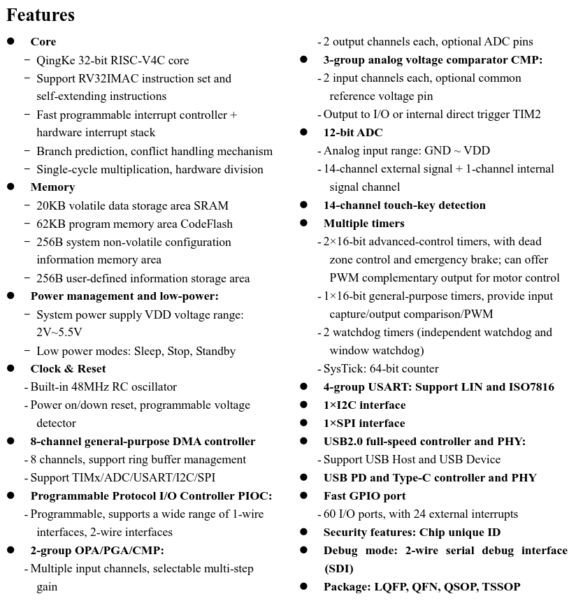
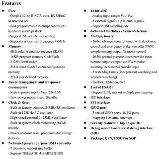
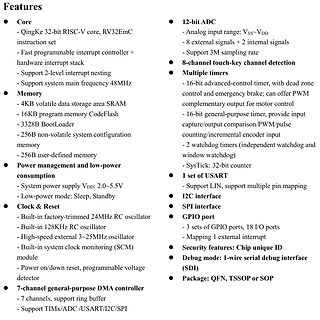
- 2 output channels each, optional ADC pins
- 3-group analog voltage comparator CMP:
- 2 input channels each, optional common reference voltage pin
- Output to I/O or internal direct trigger TIM2
- 12-bit
00000002 W COMP1_2_3_IRQHandler 08004bd9 00000002 W COMP4_5_6_IRQHandler 08004bd9 00000002 W COMP7_IRQHandler 2000021c b completed.1 08002a9f 00000002 T configHSECapacitorTuning 08002aa1 00000044 T configIPClock 08004b9a
T n - - T T 1 2 3 4 5 6 e K K S 7 5 6 X X 3 2 1 X 3 2 1 1 2 3 4 5 1 2 3 4 5 6 2 1 1 2 3 4 5 1 3 2 1 1 3 2 1 1 2 3 4 5 6 3 2 2 4 5 3 3 1 2 3 4 5 6 V D x 1 T R 2 + - i S C n D N l k r 5 n A o C 454 143/24R 25 8.3 Function

 Bild
 Bild
 Bild