schnell nichts passieren. Ich bin auch der Meinung, daß Ge-Transistoren im TO-18 o.ä. Metallgehäuse (AC126, AF126) weniger gefährdet sind als solche im Glasgehäuse (OC45,71, OC604). Dasselbe gilt für Ge-Dioden. Lass die Anschlussdrähte so lange wie möglich (Aufrollen) Mir ist früher nie etwas passiert
AF115 u.ä. "OA"Dioden. Meist mit Ausschlacht-Teilen. Halbleiter waren damals noch sündhaft teuer. Ein AC126 für 30 OE Schilling. Das war sechs Wochen Taschengeld! Heute kostet ein BC845 Pfennige. Gerhard
spät. Es war bei Dir schon spät. Weil in der Regel die meisten keine ausreichend stromstarke AC-Quelle mit 50Hz für die Primärseite zu Hause haben werden. Die Messmethode über die Sprungfunktion gäbe es auch noch.
Leerlaufbetrieb. Im Praktischen wäre das der Magnetisierungsstrom, wenn das Teil als gewöhnlicher AC-Transformator verwendet werden würde.
Norbert schrieb im Beitrag #8105275: > Seinen ersten Transistor vergisst man nie. Oder so ähnlich… AC107
Der Laden existier schon ewig nicht mehr. Und ja, in meinem ersten Elektronik Baukasten waren noch AC... und OC.. Transistoren. Die OCs im schwarz lackierten Glasgehäuse.
Bit-Muster (4 Byte für 8 Hex-Zeichen) nutzt, das sich auf einer (!) beliebigen Seite im Bereich von 0 bis 126 befindet. Demnach könnte das ffff5a6a beim Funktransponder sein und darf nur auf einer Page sein, nicht verteilt über andere Pages. 2 Byte zum füllen der ersten 16 Bits und 16 Bits einer eigenen,
mit 75 Kontakten (davon 16 nc not connected) heißt: L.C.D. 5322 130 90158 532213090158 Quelle: 126-seitiges Service-Manual Seite 81 http://bee.mif.pg.gda.pl/ciasteczkowypotwor/Philips/pm2519.pdf Das Segment-Layout sieht man im Schaltplan auf Seite 94. Keine Google-Treffer Bei Kleinanzeigen
160 Segmente ansteuerbar, davon sind 160-3=157 genutzt: BP0 BP1 BP2 BP3 Pin S00 ={DC} ~{AC} DELAY SEQU 46 S01 BURST MAX delta% AX+B 45 S02 READ MIN LIM CAL 44 S03 ??? 4W{ire} SPEAKER SHIFT 43 S04 --- HF {diode} 2W{ire} 42 S05 P8P9 Z {up} {down} 41 S06 D9
® MP900 and MP9000 Series Kool-Pak Power Film Resistors TO-126, TO-220 and TO-247 Style Page 1 of 2 MP916 Standard Resistance Values: Tolerance MP916 ±5% Standard (20% is available). 0.015 Ω 5% MP915, MP925, and MP930 Standard Resistance Values: Tolerance MP915
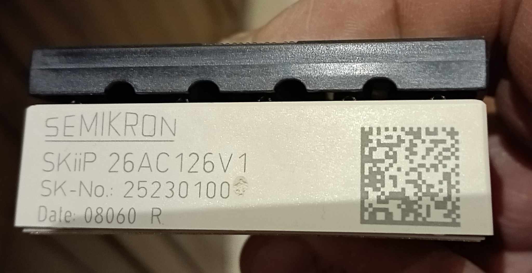
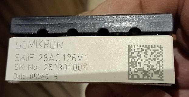
Datenblätter: IGBT Modul: https://www.tme.eu/Document/b1046be2b888139b84f63a111a31d5ce/SKiiP25AC126V1.pdf (Es ist ein 3-phasiges Modul, wovon eine Halbbrücke nicht verwendet wird) Treiber: https://www.infineon.com/assets/row/public/documents/24/49/infineon-ir2110-datasheet-en.pdf Wie kann ich
ein IGBT Modul vorgaukeln? Mittels Widerstände und Spannungsteiler, dass er die halbe PV Spannung am AC Ausgang misst? Das würde ja Symetrierungswiderständen entsprechen und grob auch schon über die Cs passieren. Habt ihr eine Idee für mich? Vielen Dank und viele Grüße Chris
Caution: Do NOT wave solder SOIC to avoid damaging SNAPHAT sockets. Doc ID 2412 Rev 8 21/33 DC and AC parameters M48T58, M48T58Y 8 DC and AC parameters This section summarizes the operating and measurement conditions, as well as the DC and AC characteristics of the device. The parameters in the following
AC18 D20 A11 V V V V V V V V V V V V V V V V V V V V V V V V V V V V V V V V AC16 VCC4 D22 VCORE +VCCP A14 VSS4 VSS157 AC14 VCC5 E5 A17 VSS5 VSS156 AC12 VCC6 E7 A20 VSS6 VSS155 AC10 VCC7 E9 A23 VSS7 VSS154
vorlie gende Band gibt eine geschlossene Obersicht über Wirkung, Schaltung und Be rechnung dieser AC-Glieder, die ähnlich wichtig wie Röhren und Transistoren sind. - Grundsätzliches über AC-Glieder. AC-Glieder als Wechselstromwider- 13 stände. Dia Zeitkonstante von RC-Giiedern. Die Phasenverschiebung
S371, 470, 471, S270, S370, 570, 571, 472, 473, 476, 477, 572, 573, S450, S451, 82S23, 82S123, 82S126, 82S129, 93426, 93427, K155PE23, HM-7648, HM-7649 Das sind aber wohl immer noch nicht alle, nur das PDF scheint alle aufzuführen. https://8bit-museum.de/supported-ics/ ist in diesem Zusammenhang
Kollektorstrom deines Regeltransistors fliesst in den 10µF rein, das ist praktisch ein Kurzschluss (AC betrachtet). Dein Regler ist totgedämft, damit regelt der nicht mehr, bzw. nur mehr Laständerungen unter 0.3 Hz. Damit hast du deine Regelschaltung effektiv durch eine Stellschaltung ersetzt, die du
Sogar von ONS. https://www.reichelt.de/de/de/shop/produkt/hf-bipolartransistor_npn_300v_0_5a_20w_to-126-216548 Ths S. schrieb im Beitrag #8045740: > Nur aus Interesse - für eine Umdimensionierung (in Form eines anderen > Projektes) auf 400V/60mA müsste außer spannungsfestere Bauteile nichts > geändert
/100* KW/UKW-Amateur-Doppelsuper (10...80 m) mit 2-m-Konverter S. 100/119* Panorama-Adapter S. 120/126* 3 RPB 42/42b Kurzwellen- und UKW-Empfänger für Amateure, Band 2, 2. Auflage Zwischenfrequenzteile von Doppel- und Dreifachsupern S. 21/27 Zf-Filter verschiedener Bauart S. 28/38 Stär-Begrenzer und
Übertrager T2 gibt die in einem festen Verhältnis zur momentanen Ausgangsspannung stehende Spannung AC-OUT2 aus. Die Schaltung aus Operationsverstärker IC8A und Schmitt-Trigger IC9 erzeugt ein PWM-Signal, dessen Pulsbreite in Abhängigkeit zur Höhe der Spannung AC-OUT2 steht. Die Verknüpfung von Pulsbreite
TSTG Storage temperature -65 to +150 ⋅C T Operating ambient temperature range SA612A -40 to +85 ⋅C A AC/DC ELECTRICAL CHARACTERISTICS TA=25⋅C, VCC = 6V, Figure 3 LIMITS SYMBOL PARAMETER TEST CONDITION UNIT Min Typ Max VCC Power supply voltage range 4.5 8.0 V DC current drain 2.4 3.0 mA fIN Input signal
Accuracy) 10m sense resistors. The ISL88731 provides 0.5% end-of-charge battery voltage accuracy. - AC-Adapter Detection The ISL88731 provides a digital output that indicates the • 11-Bit Battery Voltage Setting presence of the AC adapter as well as an analog output which • 6 Bit Charge Current/Adapter
be configured (DCFG) USER Page 2 to employ a 32 bit pattern located in any page in the range 0 to 126. RESERVED / TRIMMING Page 126 DCFG Page 127 bit 31 bit 0 MSB LSB 0 7 0 7 0 7 0 7 BIT 0H 1H 2H 3H BYTE Figure 10. EEPROM Memory Organization Page 0 holds the device Identifier, IDE, page 126 is reserved
described either in the operating instructions or in markings on the product. 2. Power Cord Protection. AC power supply cords should be placed such that no one is likely to step on the cords and such that nothing will be placed on or against them. 3. Periods of Non-use. If the product is not used for any significant period of time, the product's AC power supply cord should be unplugged from the AC outlet. 4. Foreign Objects and Liquids. Take care not to allow liquids to spill or objects to fall into any openings of the product. 5. Water or Moisture
bonding conductor to the scale. 1–40 Troubleshooting Guide Problem Causes Solution No segments – No AC power is available – Check the AC power appear in the weight supply display (1) – The AC adapter is not – Plug in the AC adapter plugged in The weight display – The load exceeds the – Unload the scale
und An Die Widerstand-Kondensator-Schaltung. wendung von Mikrocomputern. Von Eine Einführung in die AC-Schaltungs Horst Pelka. - 1. Auflage. Zweifach (Beim Verlag vergriffen, Neuauflage in band. DM 7.80. Vorbereitung.) ISBN 3-7723-0821-X ISBN 3-7723-0607-1 64 83 Mikrofon-Aufnahmetechnik. Von Mikro Einführung
the voltage (as show fig.3) of both two ends of the resistor which connecting in series with a 5V AC adapter. With square equation to calculate I : BAT V05 www.microne.com.cn Page 13 of 19 ME4056 If RCC0.25Ω, V =SV, V BAT=3.75V, T A25℃ and JA =125℃/W, we can calculate the thermal regulation charge
ee eee te eee eae 3-6 3 0 3 V de measurement se eeeeeeeeseesee eseseeseeeeeseeeeeeeeeee 3-7 3.3.2 V ac measurement eee we eee eee eee e e e e e e e 3-9 3.3.3 DC/AC current measurementS .......ccecceeeeceeseses 3-11 3.3.4 Resistance measurement ........ceecccceccccscceseee S L L 3.3.5 Temperature meaSurement
Missed Frame Count 114 CSR114 16bit Y Receive Collision Count 124 CSR124 16bit Y BMU Test Register 126 CSR126 16bit Reserved + Note: Although the PCnetISA controller has many registers that can be accessed by software, most of these registers are intended for debugging and production testing purposes
L, MD2 = H, MD3 = H, FS0 = L, FS1 = SDSEL = L, DUAL = H, D7 to D0 = LHLHLHLH 29 2002-01-07 T6963C Ac Characteristics ● Switching Characteristics (1) Test Conditions (Unless Otherwise Noted, V DD = 5.0 V ± 10%, V SS = 0 V, Ta = −20 to 70°C) Item Symbol Test Conditions Min Max Unit Operating Frequency
z 2 0 m s “ + 1 V - — Non eR es o v _ _| .__|___ N OTE:O SCLO SCOPEI N COLL. V501S] O V ~ POSITION AC 5 0 H z A 20ms 2 8 V — - — SIGNAL 5 NOTE: OSCILLOSCOPE IN PIN 2 A502 POSITION DC ov — — ‘ 5 0 H z 2 0 m s = 4 5 V : S I G N A L 6 NODE COLL. NOTE: OSCILLOSCOPE IN PIN 6 1 9 1 0 POSITION AC - 9 5 V —
ensure that the test probe is set to 10:1 dividing factor.If the previous nach vorheriger Messung mit AC-Kopplung der Koppelkondensator measurement was made on AC input, please note that the coupling desOszilloskopsaufg eladenseinkann.DurchdieEntladungüberdas capacitor in the oscilloscope will be charged
30 dBm) Overload exerted for inputs peaks greater than +35 V Maximum Input Voltage 176 V (DC + peak AC) NOTE: Installation Category I – Signals must be isolated from the mains. DO NOT CONNECT TO MAINS VOLTAGES. Full Scale Input Ranges From –22 dBu (62.5 mV RMS ) to +44 dBu (125 RMS ) in 12 6-dB steps
ip+d THBV4_0446EA Figure 4-46: Example of signal-to-noise ratio Mean value of noise component : Id AC component of noise : id(r.m.s.) Mean value of signal (noise component included) : Ip+d AC component of signal (noise component included) : i p+d(r.m.s.) Using these factors, the signal-to-noise ratio

 Bild
Bild
 Bild
Bild
 Bild
Bild
 Bild
Bild
 Bild
Bild