genauigkeitsanforderungen sowie maximale und minimale Impedanz (auch bei pullups/down), oder grenzfrequenz min/max von Filtern etc. Eigentlich eine perfekte Aufgabe für den Rechner. Also falls ich mal ganz viel zeit übrig habe wird das ein Projekt.
± 500.0 4.208127057650866 [/code] ==> d.h. die Serienschaltung hätte dann eine Toleranz von 4.208% Die Julia-Funktionen von Measurements in Java abzusetzen ist wahrscheinlich nicht so einfach.
Hoymiles Power Electronics Inc. MIS-800-2NA {240V} Hoymiles Power Electronics Inc. HM-800N {208V} Hoymiles Power Electronics Inc. HM-800N {240V} Hoymiles Power Electronics Inc. HM-800NT {208V} Hoymiles Power Electronics Inc. HM-800NT {240V/60Hz} 800W - https://de.enfsolar.com/pv/
Hoymiles Power Electronics Inc. MIS-900-2NA {240V} Hoymiles Power Electronics Inc. MIS-1000-2NA {208V} Hoymiles Power Electronics Inc. MIS-1000-2NA {240V} https://solarequipment.energy.ca.gov/Home/InverterSolarList
Auf der anderen Seite benötige ich für meinen ESP32 ebenfalls einen Modbus-Adapter, auf dem ein [_MAX485_](https://www.analog.com/media/en/technical-documentation/data-sheets/MAX1487-MAX491.pdf)-Controller für das Modbus-Signal sorgt.
RS485 Treiber sein wie ST485, SN75176BP SN75LBC176, LTC485, SIT3088E SIT3485 SIT3490 SIT65HVD75, MAX487 MAX489E MAX490E, ADM3485
, y a PARTNUMBER/STANDARDCONFIGURATIONS W a Numberof “A” “B” “C” y (10,16) “A” PartNumber Contacts Max. Max. Max. R Max. Max. 1.100 .900 .700 3 514-AG21D 14 (27,49) (22,86) (17,78) 2 . 1.220 1.010 .800 n “C” (2,54) “B” 516-AG21D 16 (30,99) (25,65) (20,32) , Max. Typ. Max. g r e i Note: Before ordering
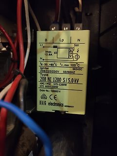
B Lp N
L1 5kV
Imax. 13.8A
B Lp N
N
ta -30..+60°C tc,max 105°C
Igniter 06242C
208/220/230V 50/60HZ
Type
208 NI 1200 S/5.0 kV
HMI / MSI 575-1200W
HTI 600/1200W
Order-No.: 10006014
CE
BIAIG electronics GERMANY
Schaltregler dieser Leistungsklasse nicht als sonderlich empfindlich bekannt. Wenn man einen für max. 3A angepriesenen Regler natürlich die meiste Zeit mit 3A betreibt oder meint, bei 3A würden Kerkos mit 10µF nominal, also abzüglich Bias-Derating, ausreichen oder beim Layout nicht nachdenkt, dann
man quasi fast alles mit einem gewöhnlichen Lötkolben anlöten – SO8, SOT23-6, SOT89 oder auch LQFP208, sofern man sich die richtigen Strategien für die vielen, verschiedenen Gehäusetypen angeeignet hat. Lötlitze in passender Breite ist gleich nach dem Flussmittel das zweitwichtigste Utensil. Löten von
available upon request. MECHANICAL DATA ¡ó Case:JEDEC DO-41,molded plastic ¡ó TerminaSTD-202,Method 208lderable per MIL- ¡ó Polarity: Color band denotes cathods end ¡ó Weight: 0.012 ounces,0.34 grams ¡ó Mounting position: any Maximum Ratings and Thermal Characteristics (T =25¡æ unless otherwise noted)
Source Current pin. Each comparator’s input operates from the negative n Pin Compatible with LTC1440, MAX921, MAX931 supplytowithin1.3Vofthepositivesupply.Thecompara - toroutputstagecancontinuouslysourceupto40mA.By APPLICATIONS eliminating the cross-conducting current that normally occur when the comparator
MECHANICAL DATA Case:JEDEC R--1,molded plastic Terminals: Axial lead ,solderable per MIL- STD-202,Method 208 Dimensions in millimeters Polarity: Color band denotes cathode Weight: 0.007ounces,0.20 grams Mounting position: Any MAXIMUM RATINGS AND ELECTRICAL CHARACTERISTICS Ratings at 25 ambient temperature
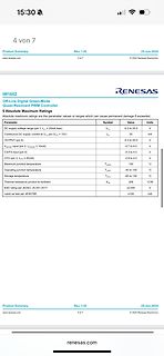
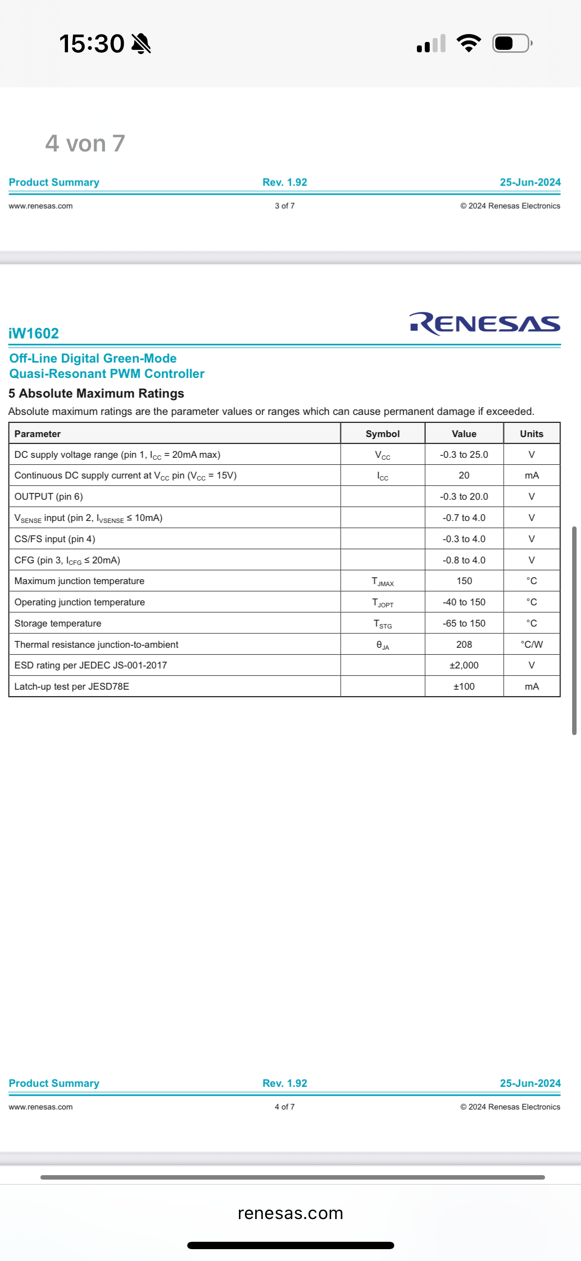
5 Absolute Maximum Ratings
Parameter Symbol Value Units
DC supply voltage range (pin 1, ICC = 20mA max) VCC -0.3 to 25.0 V
Continuous DC supply current at VCC (VCC = 15V) ICC 20 mA
OUTPUT (pin 6) -0.3 to 20.0 V
CS/FS input (pin 4) VSENSE input (pin 2, IISENSE <= 10mA) -0.7 to 4.0 V -0.3 to 4.0 V
CFG
D L b E1 E e e1 C A1 A2 A SOT23-5 package mechanical data dimensions symbol millimeters inches min max min max A 1.050 1.250 0.041 0.049 A1 0.000 0.100 0.000 0.004 b 0.300 0.500 0.012 0.020 C 0.100 0.200 0.004 0.008 D 2.820 3.020 0.111 0.119 E 1.500 1.700 0.059 0.067 E1 2.650 2.950 0.104 0.116 e 0.950
types o 2.54mm pitch, 7.5mm long standard o 2.00mm pitch, 3.68mm long low profile • Component heights max. 1.4mm on connector side max. 1.4mm on flash side • Weight (max.) 5g Figure 2: Mechanical Dimensions for U-500 1GB-4GB drive Figure 3: Mechanical Dimensions for U-500 8GB-32GB drives All dimensions
asiatischen Händlern erhalten kann. Elektor definierte folgende Mindestanforderungen an TUN: U CEO / V I C max. / A h FE ( ) P max. / W f T / MHz 20 0,1 100 0,1 100 Das sind keine hohen Anforderungen. Gehäuseform und Anschlussbelegung wurden nicht definiert. Als Beispiele für TUN gab Elektor folgende Typen an
äquivalent (U CEO variiert) Anmerkung BC 107 BC 108 BC 109 BC 147 BC 148 BC 149 BC 167 BC 168 BC 169 I C max. eigentlich zu niedrig BC 171 BC 172 BC 173 BC 182 BC 183 BC 184 BC 207 BC 208 BC 209 BC 237 BC 238 BC 239 BC 317 BC 318 BC 319 BC 347 BC 348 BC 349 BC 382 BC 383 BC 384 BC 407 BC 408 BC 409 - BC413
geführt. Wertvollere (da 32 bit kann, und SPI5 nur 16 bit, kritisch bei NSS-Automatik: z.B. wenn 2x MAX7219 in Serie angeschlossen) SPI1 kann man über Pins in der Mitte haben. Beide sind mit Arduino-Funktionen zugänglich. Über Manipulationen mit Register kann man noch SPI2 und 3 (auf Kosten von DAC) und
lieber, ein Dritter kann ohne PSSI nicht leben... Und alles zusammen kaum möglich, auch wenn LQFP-208... HAL für STM32 ist auch etwas wie Arduino, nur etwas komplizierter aufgebaut. Gestern habe ich eine Mega falsch "verfüßt". Wie kann man schnell einen Takt machen? Mit einer Arduino-Nano habe
2025 6) ABSOLUTE MAXIMUM RATINGS All Voltages with Respect to Ground Parameter Symbol Conditions Min Max Unit Supply Voltage VDDV SS - 0.3 +6 V Input Voltage VIN VSS0.3 VDD0.3 V (1) ESD Rating VHBM Human Body Model (HBM) ±2 kV VCDM Charged Device Model (2) ±1 kV Latchup Current Limit LUT For all pins ±
No Need WACY37X V5.04 CYPRESS PLD CY37512V(CQFP208) ADP-CY37256-Q208 No Need WACY37X V5.04 CYPRESS PLD CY37512V(TQFP208) ADP-CY37256-Q208 No Need WACY37X V5.04 CYPRESS Serial PROM CY3LV010 NONE No Need WSPROM V6.06 CYPRESS PLD CY7B326(PLD610) NONE No
25°C(Note2). V =V =EN =EN =10V, MODE=0V, R =200kΩ A IN_P IN_N T SYMBOL PARAMETER CONDITIONS MIN TYP MAX UNITS Boost Charge Pump VIN_P VIN_PInput Voltage Range l 4.5 16 V VUVLO VIN_PUndervoltage Lockout Threshold VIN_PRising l 3.8 4 V VIN_PFalling l 3.4 3.6 V I V Quiescent Current Shutdown, EN = EN = 0V
25 C both polariti1s Q (PNP)2& Q (NPN), unless otherwise noted) G = Pb-Free Package Rating Symbol Max Unit (Note: Microdot may be in either location) Collector-Base Voltage VCBO 50 Vdc *Date Code orientation may vary depending up- on manufacturing location. Collector-Emitter Voltage VCEO 50 Vdc Collector
H2 I H 1 L 0 - 40 0 55 85 125 150 P d Tamb(°C) Note • Zero power is considered as measuring power max. 1 % of max. power. PHYSICAL DIMENSIONS FOR RELEVANT TYPE (all dimensions in millimeters) H1 R25VALUE BMAX. d H2 MAX. L P T MAX. MIN. MAX. 3.3 to 220 5.0 0.6 ± 0.06 1.0 4.0 6.0 24 ± 1.5 2.54 4.0
H2 I H 1 L 0 - 40 0 55 85 125 150 P d Tamb(°C) Note • Zero power is considered as measuring power max. 1 % of max. power. PHYSICAL DIMENSIONS FOR RELEVANT TYPE (all dimensions in millimeters) H1 R25VALUE BMAX. d H2 MAX. L P T MAX. MIN. MAX. 3.3 to 220 5.0 0.6 ± 0.06 1.0 4.0 6.0 24 ± 1.5 2.54 4.0
character generator ROM (code 0101) T6963C−0101 is built in as standard. ▯External display memory : 64 KB Max The addresses in display memory of the text area, graphic area and external character generator area are determined by software. ▯Read or Write operations from the CPU do not disturb the display. ▯A
zusätzliche Funkti- onen erweiterbar sein. Eigenschaften • Wechselstromausgang (eine Phase): 230 VAC, max. 1 kW Leistungssteuerungsverfahren • Betriebsarten Lassen Sie uns einige etablierte Metho- den zur Leistungssteuerung einer Wech- - Schwingungspaketsteuerung selstromlast wie einen Motor betrachten.
push button “zero set on/off” 1.6. D C C U R R E N T M E A S U R E M E N T S Ranges :20mA,20mA,2.4,208 (max, input current in highest range) #10 A (20 A for max, 20 sec.) Resolution 510HAin20mArange Number of representation units £2200 Acuracy ++(0.5%ofreading+0.1%offulscale) Temperature coefficient
Name: iiyama Responsible party: Iiyama North America, Inc. Address: 1560 Brookhollow Drive, Suite 208, Santa Ana, CA 92705 U.S.A. Telephone number: 714-437-5111 This equipment complies with Part 15 of the FCC Rules. Operation is subject to the following two conditions: (1) This equipment may not cause
.94 Figure 88: 24-hour HDOP values, in area with with no shadow/obstruction of satellite visibility (max. HDOP < 1.9).......................................95 Figure 89: 24-hour HDOP values, in area with with strong shadow/obstruction of satellite visibility (max. HDOP > 20)............................
and V ds being the intrinsic drain-source voltage. The charge and capacitances are: for V > V new max 168 V max Vnew − V max Q gs = Cgs0· 2·Vbi 1 − 1 − + (11.364) V bi 1 − VVax bi ∂Q gs C gs0 ∂Vnew = · (11.365) ∂Vgs 1 − VVax ∂V gs bi ∂Q gs C gs0 ∂Vnew = · (11.366) ∂Vgd 1 − VVax ∂V gd bi and
59 C617 T 43 13 C817 T 50 62 C928 T 143 33 C1424 T 42 105 L701 T 170 15 R129 T 18 78 R608 T 38 28 C208 T 85 58 C618 T 43 25 C818 T 16 65 C929 T 93 97 C1425 T 39 103 L702 T 174 15 R130 T 108 64 R609 T 38 25 C209 T 85 57 C619 T 48 21 C819 T 51 61 C930 T 112 97 C1426 T 65 81 L703 T 172 10 R131 T 108 62
4). WARNING Automatic placement systems from the SIPLACE family are powered with 3 x 400 VAC (3 x 208 VAC for the U.S.A. version) ± 5 %, 50/60 Hz main power voltage.This means that some parts of the system carry potentially lethal voltages - even when switched off at the main power switch.Death, serious
measure anode luminous sensitivity) VOLTAGE 0 V ON LIGHT LEVEL OFF 5 6 7 8 9 (minutes) 1 µA ANODE I max. OUTPUT Ii I min. OR Ii I max. I min. 5 6 7 8 9 (minutes) WARM-UP PERIOD (5 minutes or more) THBV4_0440EA Figure 4-40: Light hysteresis In light hysteresis test, the photomultiplier tube is operated
routine examines the Rdown and Rup bits in the range control status register. Ifthe range > range max. then the instrument must range up. Ifthe range < range min. then the instrument must range down. Italso ensures that in the TRIGGER LEVEL function only manual ranging isallowed. 1.4.1.4. M e a s u

 Bild
 Bild
 Bild
 Bild
 Bild